
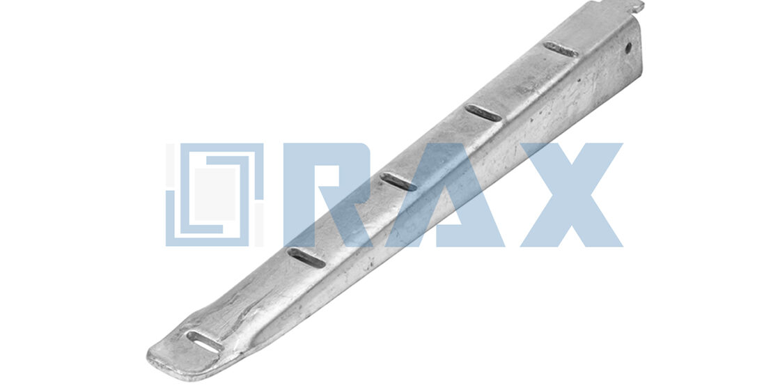
Ultimate break strength is a vanity metric for pole line hardware. It ignores micro-fractures caused by daily vibration. Most EPC engineers specify inferior galvanization when reviewing quotes for a cable rack hook because suppliers hide coating thickness behind generic corrosion resistant labels. We mandate hot-dip galvanizing that consistently exceeds 85 microns of zinc coating at Rax Power because thin electroplated layers crack under wind sway. That single coating metric dictates whether your connections survive heavy wind loads or develop dangerous play within months.
We skip the marketing fluff and drill into the mechanical realities EPC teams control. This breakdown examines Q235 steel grain flow during automated hot-forging, ±1mm dimensional tolerances, and how IEC 120 proof loads calculate actual dynamic safety factors. You will get precise threshold values to vet incoming hardware and catch substandard manufacturing before it reaches your site.
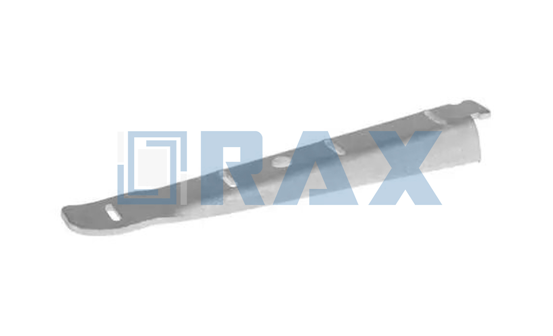
Cable Rack Hook Material Standards
Selecting the correct base alloy and metallurgical coating threshold dictates whether pole line hardware survives decades of dynamic loading or fails prematurely due to corrosion fatigue.
Q235 Steel Substrate and Surface Chemistry
The durability of cable rack hooks begins with the chemical composition of the substrate. Q235 carbon steel is the industry standard for overhead line hardware due to its optimal balance of tensile strength and ductility. Unlike higher carbon steels that can become brittle during thermal processes, Q235 maintains structural integrity while providing a chemically reactive surface ideal for galvanizing. This specific silicon and phosphorus content facilitates the formation of a strong zinc-iron alloy layer during the hot-dip process, which is critical for long-term adhesion. If the substrate chemistry is not correctly controlled, the reaction with molten zinc can be unpredictable, leading to coating delamination under load.
In our production protocol, we strictly source Q235 steel with verified chemical mill certificates. We have found that this rigorous material vetting eliminates the risk of “sand-casting” porosity often seen in lower-grade alternatives, ensuring that the galvanized coating adheres uniformly to a dense, non-porous surface.
The Critical Difference: Zinc Plating vs. Hot-Dip Galvanizing
A common failure point in secondary rack systems is the misapplication of electroplating (zinc plating) instead of hot-dip galvanizing. Electroplating deposits a thin layer of zinc onto the surface through an electrical current. This creates a physical barrier, but it lacks the metallurgical bonding required for heavy mechanical applications. Under the vibration and static loads inherent in pole line hardware, electroplated layers are prone to micro-cracking and flaking. Once the plating is breached, corrosion accelerates rapidly, compromising the hook’s load-bearing capacity.
Hot-dip galvanizing, by contrast, immerses the steel component in a bath of molten zinc (typically exceeding 450°C). This triggers a diffusion reaction that forms four distinct intermetallic zinc-iron alloy layers. These layers are harder than the underlying steel and are integrated into the surface, rather than just sitting on top of it. We utilize this method because it ensures that even if the hardware is scratched during installation, the surrounding coating provides sacrificial cathodic protection, preventing rust from spreading.
ISO 1461 Thickness Standards and Service Life
Corrosion resistance is directly proportional to coating thickness. For utility hardware exposed to industrial pollution or coastal saline environments, the ISO 1461 standard is not merely a guideline—it is a survival requirement. The standard specifies a mean coating thickness that acts as a reservoir of protection; a mean thickness exceeding 85 microns provides a significant service life extension compared to standard commercial coatings. This thickness ensures that the weathering rate of the zinc allows the coating to outlast the designed operational life of the pole line hardware, even in harsh Class C4 or C5 corrosivity environments.
- Surface Roughness: Proper galvanizing adds a slightly textured finish, which actually aids in paint adhesion if additional color coding is required by utility standards.
- Abrasion Resistance: The thick alloy layers generated by our ISO 1461 compliant process resist the mechanical wear that occurs during transportation and installation.
To guarantee compliance, our quality team performs mandatory coating thickness verification on every batch. We reject any production run that falls even marginally below the 85-micron mean, as we know from our export experience that international utility auditors will not compromise on corrosion protection metrics.
| Parameter | Specification | Technical Advantage | Quality Assurance | Commercial & Procurement Edge |
|---|---|---|---|---|
| Base Material & Forming | Q235 Steel via Automated Hot-Forging | Eliminates internal voids for superior ductility and fatigue resistance under high tension | In-house IEC 120 load and gauge testing with full SGS verification | Optimized for rapid EPC technical validation and direct factory pricing |
| Dimensional Precision | ±1mm Strict Manufacturing Tolerance | Prevents onsite installation delays and ensures stable load transfer in secondary rack connections | Mandatory 100% double-review inspection protocol prior to packaging | Flexible MOQ and customized lead times tailored to project schedules |
| Surface Protection | ISO 1461 Hot-Dip Galvanizing (>85μm mean thickness) | Maximum corrosion resistance for extreme climates and long-term grid reliability | Strict coating thickness verification with mandatory batch certification | Streamlined sample approval workflows aligned with global utility procurement |
| Structural Grain Control | Hot-forged steel grain structure optimization | Delivers higher breaking load capacity compared to traditional sand-casting methods | Continuous mechanical property tracking aligned with global utility procurement metrics | OEM/ODM capabilities for custom mold development and regional tender specifications |
| Supply Chain Readiness | 21-year export optimized production line | Consistent high-volume output without compromising dimensional accuracy | Rigorous pre-shipment verification ensuring compliance with highest international standards | Dedicated project engineering support from initial inquiry to final delivery |
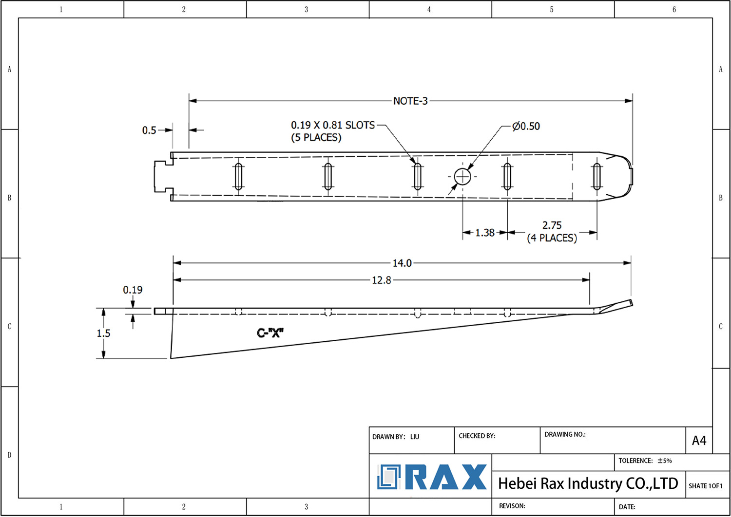
Hot-Forging vs Casting Methods
Manufacturing Process: Thermal Compression vs. Fluid Deposition
The fundamental difference between hot-forging and casting lies in the state of the raw material during formation. Casting relies on pouring molten metal into a mold, where it cools and solidifies. While cost-effective for complex shapes, this process is vulnerable to impurities settling and inconsistent cooling rates. In contrast, hot-forging applies intense thermal energy and compressive force to a solid steel billet, deforming it plastically to take the shape of the die. We have strictly adopted automated hot-forging to replace traditional sand-casting, ensuring that the material’s density is increased through mechanical pressure rather than relying on the unpredictable settlement of fluid metal.
Grain Structure Alignment and Fracture Resistance
The mechanical superiority of hot-forging is primarily rooted in the manipulation of the steel’s grain structure. In cast components, the grain structure is randomized and globular, creating planes of weakness that can propagate cracks under stress. Hot-forging realigns these grains, forcing them to flow along the contour of the part. Much like the grain in a piece of wood, this directional alignment allows the hardware to absorb energy more efficiently. By aligning the steel grain structure through high-pressure forging, we produce components that exhibit superior ductility and fatigue resistance, significantly reducing the risk of brittle fractures during high-tension events or dynamic load shifts.
Elimination of Internal Voids and Porosity Risks
One of the most critical failure modes in pole line hardware is internal porosity, often found in cast products. As molten metal cools, trapped air creates microscopic pockets or voids that act as stress concentrators. These invisible defects can drastically compromise the actual load capacity of a component, leading to sudden failures below the rated working load. The compressive nature of hot-forging crushes the internal structure of the steel, effectively welding these gaps shut and creating a homogeneous mass without air pockets. Our manufacturing process guarantees these voids are eliminated, ensuring that the structural integrity calculated during the design phase is physically present in every unit shipped.
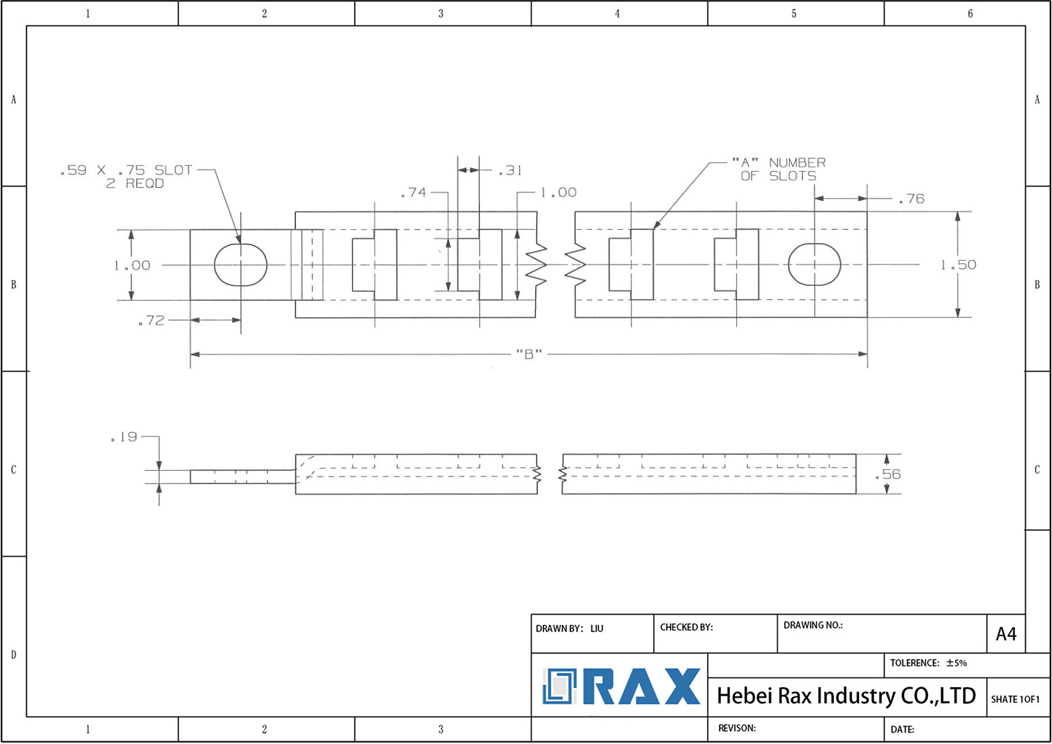
Dimensional Tolerance Benchmarks
TL;DR: Dimensional accuracy is not just about fit; it is a primary determinant of fatigue life. For secondary rack hardware, a strict ±1mm tolerance on shank length and eye diameter is required to prevent vibration-induced failure and ensure zero onsite rework.
The Criticality of Eye Diameter and Shank Length
In overhead line infrastructure, the interface between hook and rack is a high-stress point where minor dimensional variances can escalate into critical structural failures. The eye diameter dictates the interface area with the connecting bolt or pole band; an undersized eye forces assembly delays or field modifications, while an oversized eye distributes load unevenly across the contact surface. Similarly, shank length directly impacts thread engagement and clamping force. If the shank is too short, the nut cannot achieve full thread engagement, compromising the integrity of the entire assembly under load.
1mm Automation Precision: Eliminating Manual Variance
Achieving consistent dimensional accuracy across high-volume production batches is impossible with manual processes alone, which are inherently subject to human fatigue and error. To guarantee interchangeability and safety, we utilize advanced automated and semi-automatic machinery in our forging and finishing lines. This technological integration ensures that every unit meets a strict ±1mm tolerance standard, effectively eliminating the drift often seen in manual manufacturing.
- Tolerance Standard: Strict ±1mm dimensional control on critical axes (shank length, eye diameter).
- Process Consistency: Automated machinery ensures zero variance between the first piece and the ten-thousandth piece in a batch.
- Verification: A dedicated 10-person QC team performs gauge testing to validate these automated results before packaging.
Eye Diameter Compatibility and Vibration Fatigue
A loose fit is rarely a static problem; it is a catalyst for dynamic failure. When the eye diameter exceeds the upper tolerance limit, it creates “play” or mechanical clearance within the connection point. Under operational conditions—specifically wind-induced Aeolian vibration—this slack allows the connected hardware to hammer against each other. This repetitive impact creates stress concentrations that initiate micro-cracks, leading to vibration fatigue and eventual fracture. We ensure our eye diameters are machined to the tighter end of the tolerance spectrum to provide a snug, secure fit that dampens vibration rather than amplifying it.

Load Testing & Compliance
Grid infrastructure demands verifiable mechanical resilience. Overhead line hardware relies on standardized proof-load protocols and calculated safety margins to pass utility procurement audits and ensure decades of fault-free operation.
Utility verification processes for pole line hardware focus heavily on traceability, batch consistency, and documented compliance rather than general material claims. Procurement engineers and general contractors require a transparent audit trail that demonstrates each component meets exact grid code specifications before installation. Our factory implements a mandatory 100% double-review inspection protocol, where a dedicated quality control team validates every unit against dimensional drawings and surface finish requirements. This rigorous screening eliminates the risk of shipping non-compliant batches, which frequently causes costly project delays and onsite rework. We align our documentation package with major international tender standards, providing clear material certifications, test reports, and packaging logs that facilitate the EPC approval workflow.
Utility Project Verification Processes
- Batch Sampling & Third-Party Audits: Utilities typically require independent verification before full deployment. We prepare for these audits by maintaining consistent production logs and offering third-party laboratory coordination to validate mechanical properties on-site or within our facility.
- Documentation Traceability: Every shipment is accompanied by thorough test certificates and inspection records. This transparency allows utility engineers to quickly validate compliance without requesting additional field samples or delaying commissioning schedules.
IEC 120 Proof Load Testing (Proof vs. Ultimate Tests)
Understanding the operational distinction between proof testing and ultimate testing is essential for specifying reliable pole line hardware. Proof testing applies a predetermined tensile force to verify that a component successfully returns to its original dimensions after stress removal, confirming it possesses adequate yield strength without suffering permanent deformation. This method is highly effective for routine quality assurance because it preserves the integrity of the tested sample while validating structural performance. In contrast, ultimate testing continuously increases tension until the hardware fractures, which is inherently destructive and entirely unsuitable for batch inspection. In our testing laboratory, we conduct non-destructive proof load evaluations on statistically significant sample sizes to guarantee that every manufactured unit can safely handle peak operational tension. This approach allows us to maintain high production throughput while strictly adhering to international grid standards.
Safety Factor Calculations (2:1 or 3:1 Margins for Dynamic Loads)
Overhead transmission lines operate under highly variable environmental conditions, making safety factor calculations a critical component of hardware selection. Engineers apply 2:1 or 3:1 safety multipliers to account for unpredictable dynamic forces such as sudden wind gusts, heavy ice accumulation, thermal contraction, and long-term cyclic fatigue. These margins ensure that the installed hardware can absorb transient shock loads without reaching its yield threshold. We design our components to handle these multipliers through controlled ductility and consistent grain alignment, rather than relying solely on rigid strength. When contractors calculate required breaking strength for a specific span, they factor in these dynamic coefficients alongside the base static tension. Our manufacturing controls prioritize tight tolerance enforcement and uniform heat treatment precisely to support these high safety thresholds across demanding utility contracts.
When evaluating suppliers for large-scale grid projects, request their in-house proof-load testing logs rather than relying solely on external certificates. Direct access to batch-specific verification data significantly reduces procurement risk and accelerates utility approval timelines.
Conclusion
Stop risking your reputation on sand-casting hooks that crack under load. Utility projects demand precision, not vague promises. If you’re dealing with onsite delays because the eye diameter doesn’t fit the rack, you’re burning money. You need grain structure alignment from hot-forging to ensure the hardware survives dynamic tension without brittle fracture. We don’t guess with tolerances; we guarantee ±1mm precision to stop vibration fatigue before it starts. That is the only way to secure a long-term installation.
We have spent 21 years perfecting automated hot-forging to eliminate internal voids completely. Our facility uses ISO 1461 galvanizing standards to push service life past the industry average, backed by full SGS verification. Don’t settle for parts that fail the proof load test. Contact our engineering team today to get hard metrics on mechanical properties and physical samples for your next validation phase.
Frequently Asked Questions
Why choose steel over aluminum for racks?
Carbon steel offers superior tensile strength and cost efficiency for heavy-duty pole line applications. Its higher modulus of elasticity provides better resistance to deformation under extreme mechanical stress. Steel also demonstrates more predictable fatigue behavior when subjected to continuous vibration loads.
What testing verifies fatigue resistance under tension?
In-house cyclic loading simulations replicate decades of operational stress within compressed laboratory timeframes. Engineers monitor crack propagation and measure elongation limits until predefined failure thresholds are reached. This data validates structural reliability before components enter active grid deployment.
What quality certifications accompany bulk shipments?
Every production batch undergoes mandatory SGS verification alongside comprehensive IEC 120 load testing. A dedicated inspection team executes double-review protocols to confirm dimensional accuracy and coating uniformity. These documented validations streamline EPC technical approvals and accelerate customs clearance processes.
Does Raxpower support custom design projects?
Our engineering team facilitates full OEM and ODM development through dedicated custom mold creation. Clients can submit physical samples, technical drawings, or conceptual requirements for tailored manufacturing. We manage the entire prototyping-to-production pipeline to align with specific utility procurement standards.