
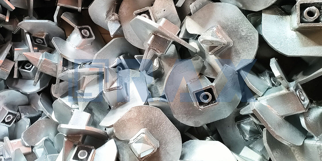
Structural failure in utility infrastructure rarely starts at the pole top; it initiates at the anchor point where tensile load meets aggressive soil chemistry. Earth anchor rods act as the critical transfer mechanism, absorbing kinetic energy from wind shear while buried in degrading environments. Rax Power manufactures these components using ISO 1461 compliant hot-dip galvanizing that ensures coating thicknesses exceed 85 microns, a necessary defense for long-term structural integrity.
This guide analyzes soil load factors and embedment depth requirements alongside the critical selection of steel grades and corrosion-resistant coatings. We also dissect the specific failure risks associated with mixed galvanizing processes and grout pad moisture accumulation. You will learn how to specify rods that maintain fatigue resistance and prevent galvanic failure, ensuring your project uptime remains unaffected by foundation instability.
Soil Load Factors and Embedment Depth
Underestimating soil complexity is the leading cause of anchor failure. Load capacity is not just about the steel grade; it is about the interaction between the anchor and the geotechnical environment.
Analyzing Soil Classification Effects on Capacity
Soil classification is the primary determinant of an anchor’s ultimate load capacity. In loamy or soft soils, the holding power relies heavily on the friction between the soil and the anchor surface. For these conditions, the installation torque is a critical metric; as the anchor penetrates, it displaces and compacts the surrounding soil, generating the necessary resistance to pull-out. The effectiveness of this mechanism dictates the specific anchor configuration required for stability.
Conversely, rocky or compact terrain presents a distinct engineering challenge where friction-based systems often fail due to the inability to penetrate. In these scenarios, the system must rely on a mechanical lock or bearing pressure against solid strata. We have found that for these high-stress environments, hot-forged expanding anchors provide superior tensile strength compared to traditional casting methods. This ensures that the anchor maintains structural integrity under the point loads encountered in hard ground, preventing the shearing risks common with weaker manufactured components.
Determining Minimum Embedment Depth
Determining embedment depth is a calculation of the ‘failure wedge’ rather than a rule of thumb. If an anchor is set too shallow, an uplift force will cause a cone of soil to lift with the anchor, drastically reducing holding capacity. Proper embedment ensures that the weight and shear strength of the soil mass above the anchor are sufficient to counteract vertical forces. Engineers must calculate this depth based on the soil’s shear strength parameters and the specific angle of internal friction.
| Soil Condition | Embedment Depth | Load Factor | Rax Power Solution | Engineering Advantage |
|---|---|---|---|---|
| Loamy / Soft Soil | Deep Penetration | High Resistance to Pull-out | Helical Square Shaft Anchors | High Torque Installation for Stability |
| Rocky / Compact Terrain | Variable / Standard | High Tensile Strength Required | Hot-Forged Expanding Anchors | Superior Strength vs. Casting Methods |
| Corrosive / Wet Environments | Project Specific | Fatigue Resistance & Coating Integrity | ISO 1461 Galvanizing (>85 Microns) | Protection Against Moisture Ingress & Rust |
| Extreme Climates (e.g., Russia) | Engineered for Safety | High Breaking Load Demands | SGS Verified Custom Designs | Reliability in Harsh Environments |
Selecting Anchor Rod Eye Configurations
The anchor rod eye is the primary stress concentration point in the guy assembly; selecting the correct configuration prevents fatigue failures and ensures load transfer efficiency.
When specifying anchor rods for overhead line infrastructure, the configuration of the eye—whether it is a thimble eye, forged eye, or a hook variant—dictates the reliability of the entire anchoring system. A poorly selected eye geometry can lead to uneven load distribution, resulting in premature guy wire failure. For utility projects requiring maximum uptime, the choice must balance ease of installation with high-cycle fatigue resistance.
Thimble Eye vs. Forged Eye Variants
The most common configuration for distribution and transmission poles is the Thimble Eye Anchor Rod. This design features a closed loop specifically engineered to house a thimble, protecting the guy wire from bending stress and abrasion. However, not all thimble eyes are created equal. The internal radius of the eye must match the thimble profile exactly; otherwise, the assembly sits loose, transferring vibration directly to the steel rod rather than the thimble.
In high-load applications, such as the extreme environment projects we supply in Russia, standard stamped eyes can be a liability. Instead, a hot-forged eye is preferred. This process aligns the metal’s grain flow around the contour of the eye, significantly enhancing tensile strength and ductility compared to welded or bent bar alternatives.
Hot-Forging vs. Casting: The Structural Integrity Factor
A major pitfall in B2B procurement is sourcing anchor rods with cast eyes due to their lower initial cost. Castings are prone to internal voids and porosity, which act as initiation sites for cracks under dynamic loads. At Rax Power, we have eliminated this risk by utilizing advanced hot-forging technology for our critical hardware. Our engineering data confirms that hot-forged eyes offer superior impact resistance, ensuring the hardware can withstand the sudden shock loads often encountered during severe weather events.
- Grain Structure Alignment: Hot-forging refines the internal grain structure, creating a continuous path along the eye’s curve for maximum strength.
- Dimensional Consistency: Our automated machinery maintains a strict tolerance on eye diameter, ensuring a seamless fit with standard thimbles without the need for field modification.
- Defect Reduction: Unlike casting, our forging process eliminates internal porosity, reducing the risk of catastrophic snap failures under tension.
Coating Consistency and Fitment Tolerances
The configuration of the eye must also account for the galvanizing process. A common “bullshit” scenario in the industry is receiving anchor rods where the galvanizing thickness is inconsistent between the eye and the shank, or where excess zinc has clogged the eye opening. This forces installation crews to ream the eyes on-site, damaging the corrosion protection and inviting rust. We strictly adhere to ISO 1461 standards, ensuring a mean coating thickness exceeding 85 microns while utilizing centrifugal techniques to keep the eye interior clean and functional.
Our 10-person QC team executes a double-review process specifically checking the eye’s internal diameter post-galvanization. This ensures that when the hardware arrives on site, the thimble slides in every time, preserving the protective zinc layer and guaranteeing the service life of the asset.
Comparing Steel Grades and Tensile Strength
Selecting the correct steel grade is not just about meeting a minimum tensile spec; it is about ensuring the ductility and grain structure can withstand dynamic wind and ice loads without catastrophic failure.
Distinguishing between yield strength and ultimate tensile strength is essential for proper utility pole anchoring. Many procurement officers focus solely on the ultimate tensile strength (UTS), but yield strength is the critical threshold where permanent deformation begins. For standard static loads, lower carbon steels provide sufficient strength with high ductility. However, for regions experiencing extreme weather or heavy ice loading, high-strength alloys are necessary to maintain structural integrity under tension.
Common Grades and Application Scenarios
Industry standards often reference ASTM F1554 Grade 55 or similar mild carbon steels for general anchoring due to their excellent weldability and ductility. However, as transmission voltages and pole heights increase, the demand for higher strength grades rises. In the Russian market, for instance, we frequently encounter specifications requiring materials with significantly higher breaking loads to compensate for permafrost soil shifts and extreme wind gusts. In these scenarios, standard mild steel is insufficient, necessitating the use of higher-grade alloys or quenched and tempered steels to achieve the required safety factors.
The Manufacturing Factor: Forging vs. Casting
The stated tensile strength on a mill certificate is theoretical; the realized strength in the field depends entirely on the manufacturing method. Many competitors utilize casting for complex shapes like eyes and tongues, but this process introduces porosity and inconsistent grain structures that significantly weaken the component under load. We strictly utilize hot-forging for our critical hardware. This process aligns the grain flow of the steel with the contour of the part, resulting in a fatigue resistance and impact strength that far exceeds cast equivalents of the same nominal grade.
Evaluating Corrosion Resistant Coatings
A corrosion resistant coating acts as a sacrificial anode system. If the metallurgical bond is weak or the substrate is porous, the barrier fails, exposing the core steel to rapid oxidation.
The baseline for evaluating overhead line hardware is compliance with ISO 1461. However, mere adherence to this standard does not guarantee longevity if the immersion process is rushed. True protection requires a controlled chemical reaction that ensures the zinc layers alloy with the iron substrate. This creates a defense mechanism that remains intact even if the surface is scratched, preventing the “red rust” that compromises structural integrity.
We have observed that the industry average often leaves hardware vulnerable during the logistics phase—the critical time between shipping and installation. To counter this, we apply a coating density that substantially exceeds the typical baseline. This high-density barrier creates a physically thicker envelope, ensuring that the rod maintains total protection even against minor abrasions that occur during rough handling or transport.
Evaluating the coating requires checking the base material integrity. Cast components often suffer from internal porosity; moisture gets trapped under the zinc, causing unseen rot from the inside out. We rely on hot-forging technology to produce a dense, pore-free steel substrate. Because the underlying structure is solid, the protective layer adheres uniformly, eliminating the risk of sub-surface corrosion that plagues inferior manufacturing methods.
| Criteria | Standard | Technical Specification | Quality Assurance | Engineering Benefit |
|---|---|---|---|---|
| Coating Process | ISO 1461 Compliant | Hot-Dip Galvanizing | SGS Verified | Ensures comprehensive coverage and uniform protection against environmental elements. |
| Coating Thickness | Exceeds Industry Baseline | > 85 Microns | In-house Gauge Testing | Provides a dense, robust barrier that significantly extends service life. |
| Surface Quality | Premium Finish | Smooth and Bright | 100% Double-Review Process | Reduces friction during installation and prevents coating cracks. |
| Base Material Integrity | Superior to Casting | Hot-Forging Technology | Rigorous Load Testing (IEC 120) | Eliminates structural porosity, preventing internal corrosion and fatigue failure. |
Preventing Galvanic and Fatigue Failure
Galvanic corrosion and fatigue failure are the primary silent killers of overhead line infrastructure, often initiating at the microscopic level long before a break is visible.
Galvanic corrosion occurs when dissimilar metals interact in an electrolyte, such as water trapped in a grout pad, leading to rapid material degradation. Fatigue failure is frequently the mechanical consequence of this chemical process; corrosion pits act as severe stress concentrators, drastically reducing the rod’s ability to handle dynamic wind loads and vibration.
The Critical Role of Coating Thickness
Standard mechanical plating often leaves microscopic pores in the coating, allowing moisture to reach the substrate steel within months. We strictly adhere to ISO 1461 standards for our hot-dip galvanizing, ensuring a mean coating thickness that consistently exceeds 85 microns. This metallurgical bond creates a uniform barrier that prevents the electrochemical reaction necessary for rust to initiate.
Mitigating Fatigue Through Grain Structure
Fatigue cracks rarely start in solid steel; they originate in voids and inclusions. While traditional casting methods can trap air pockets that become stress raisers, our hot-forging process compresses the steel’s internal structure. By aligning the grain flow with the rod’s contour, we eliminate the microscopic weak points where fatigue failure typically begins.

Ensuring Fastener and Thread Compatibility
Achieving proper thread engagement is often compromised by dimensional variances in coating thickness. Even with premium steel, a nut that binds halfway down the shank due to coating build-up renders the entire assembly unsafe.
The primary friction point in pole line hardware assembly often occurs at the thread interface, specifically when hot-dip galvanizing is involved. While ISO 1461 compliant coating provides essential corrosion protection—exceeding 85 microns in our production—it significantly alters the dimensional profile of the fastener. If the threading process does not account for this added material build-up, the resulting friction prevents proper nut engagement, leading to incomplete thread contact and potential pull-out failure under dynamic loads.
The Galvanizing Dilemma: Dimensional Accuracy vs. Protection
Industry standards dictate that hot-dip galvanized threads must be overtapped to accommodate the zinc layer. However, variance in galvanizing thickness can lead to mismatched tolerances if bolts and nuts are sourced from different suppliers. We consistently encounter field failures where a high-spec nut fits loosely on a rod or seizes on a heavily coated thread due to process misalignment. To mitigate this, we employ a synchronized manufacturing approach where the male and female threads are processed with complementary allowances to ensure a snug, interference-free fit.
Verification via Gauge Testing (IEC 120)
Visual inspection is insufficient to guarantee thread compatibility. We rely on rigorous gauge testing compliant with IEC 120 standards to verify thread integrity after galvanizing. This involves using precision ‘Go’ and ‘No-Go’ gauges to physically verify that the zinc coating has not encroached beyond the allowable tolerance limits.
OEM/ODM Thread Customization
For projects requiring specific non-standard hardware or integration with legacy infrastructure, compatibility extends beyond standard metric or imperial threads. We offer custom mold development to match your existing nut inventory or specific base plate requirements. By supplying us with your mating component or detailed drawings, we can manufacture the opposing thread to exacting specifications, ensuring seamless integration without the need for on-site rework.
Installation Torque and Handling Procedures
Preserving the integrity of the galvanized coating during installation is as critical as the manufacturing quality itself. Overtorquing or rough handling shears the protective zinc layer, exposing the substrate to corrosion and compromising the anchor rod’s design life.
Applying Correct Torque Settings
Galvanized anchor rods typically feature a coating thickness exceeding 85 microns to meet ISO 1461 standards. This build-up is vital for corrosion resistance but fundamentally changes the thread engagement dynamics. Standard torque values for uncoated steel often exceed the yield point of the zinc layer, causing the coating to flake or crack under stress. To prevent this, installation torque must be calibrated specifically for hot-dip galvanized fasteners, or galvanized nuts must be used with proper clearance to accommodate the coating thickness without stripping the threads.
We emphasize this because our internal testing shows that even minor coating breaches at the thread crest accelerate corrosion significantly in saline environments. Our 10-person QC team ensures every rod leaves the factory with perfect dimensional accuracy, but maintaining that protection requires the installer to use a calibrated torque wrench rather than brute force.
Preventing Thread Deformation During Handling
Thread deformation not only prevents nut engagement but also concentrates stress, reducing the fatigue life of the assembly. While our hot-forging technique provides superior density and strength compared to traditional casting, the threads remain the most vulnerable part of the component during logistics. Dropping rods or allowing them to strike against concrete or steel structures can roll over the thread roots, making assembly impossible without damaging the nut.
📋 Actionable Steps
- Step 1: Use thread protectors or plastic caps during all transportation and storage phases to shield the threaded ends from impact.
- Step 2: Lift rods using non-metallic slings or designated lifting points to avoid contact between the threads and chains or hooks.
- Step 3: Inspect threads immediately before installation using IEC 120 compliant gauge checks to ensure no deformation occurred during offloading.
By treating the threaded section as a precision instrument rather than raw construction material, contractors ensure the high-breaking load capacity we engineered into the rod actually translates to the pole line structure.
Grout Pad Moisture and Maintenance
Standing water in grout pads creates a corrosive electrolyte bath that rapidly compromises anchor rod integrity. Ensuring proper drainage and seal integrity is the most cost-effective maintenance strategy.
Water accumulation at the base of utility poles is a primary driver of premature anchor rod failure. When grout pads are improperly leveled or lack drainage features, they act as reservoirs, holding moisture against the base plate and rod projection. This constant exposure, particularly when combined with de-icing salts or industrial pollutants, accelerates corrosion rates far beyond standard atmospheric conditions. Preventing this requires a combination of geometric design during installation and vigilant maintenance.
Mitigating Water Accumulation
📋 Actionable Steps
- Step 1: Design the grout pad surface with a minimum slope (typically 1:48) away from the pole base to facilitate natural runoff.
- Step 2: Install functional weep holes or drainage channels at the lowest point of the grout ring to allow trapped water to escape the structure.
- Step 3: Utilize non-porous, high-density grout mixtures to minimize water absorption and prevent capillary action from drawing ground moisture up to the steel.
Even with optimized drainage, the interface between the steel base plate and the concrete grout remains a critical vulnerability. If the sealant here fails, the collection area underneath the plate becomes a hidden pocket for corrosion. Regular inspection protocols must focus heavily on this transition zone to catch breaches before they lead to structural degradation.
Inspecting Seals to Prevent Moisture Ingress
📋 Actionable Steps
- Step 1: Conduct an annual visual inspection of the sealant bead around the entire perimeter of the base plate, looking for gaps, cracks, or shrinkage.
- Step 2: Scan the surface of the grout for rust stains or streaks emanating from under the plate, which are clear indicators of active internal leakage.
- Step 3: Immediately remove compromised material and reapply a flexible, polyurethane-based sealant designed for UV resistance and thermal movement.
Conclusion
Mechanical strength means nothing if corrosion pitting destroys your fatigue resistance first. You must insist on hot-dip galvanizing for every component to prevent dimensional inconsistencies and eventual failure in wet grout pads. Don’t mix mechanical zinc with hot-dip parts. Matching the coating process to the steel grade secures the embedment against soil shifts.
Our facility exceeds ISO 1461 standards with coating thicknesses over 85 microns to handle these harsh environments. We back that with a 10-person QC team and 100% double-reviews. If you are dealing with complex soil conditions or specific regional standards, send us your drawings. Our engineers can review your requirements for a custom feasibility assessment.
Frequently Asked Questions
How to select the correct anchor rod?
Selection depends primarily on soil type, load requirements, and the specific environmental conditions of the installation site. Engineers must calculate the required tension and shear loads to determine the appropriate diameter and grade of the steel. Consulting geotechnical reports ensures the chosen anchor rod can withstand the specific pull-out resistance needed for the project.
How do anchor rods ensure pole line stability?
Anchor rods transfer mechanical loads from the pole structure deep into the soil, effectively resisting uplift and overturning forces. By securing the structure to a firm foundation, they prevent leaning or collapse during high wind events or heavy ice loading. Proper installation ensures the long-term integrity of the entire transmission line system.
What is the best coating for corrosion resistance?
Hot-dip galvanizing is widely regarded as the most robust and cost-effective coating for steel anchor rods in utility applications. This process creates a metallurgical bond that provides superior barrier protection and cathodic defense against rust. For extreme environments, additional zinc-rich coatings or stainless steel options are often specified.
Can hot-dip galvanizing affect high-strength steel?
Yes, if not controlled properly, the high temperatures of the galvanizing process can potentially cause hydrogen embrittlement in high-strength steels above grade 10.9. However, reputable manufacturers manage this through specific heat treatment protocols to ensure material properties remain intact. At Raxpower, we strictly monitor thermal profiles to preserve the tensile strength of our anchor rods during coating.
How to address Galvanic Corrosion Risk?
To mitigate galvanic corrosion, it is critical to ensure dissimilar metals, such as galvanized steel and copper grounding, are electrically isolated. Using non-conductive separators or dielectric union fittings prevents the flow of ions that leads to accelerated metal loss. Regular inspections of coupling points help identify early signs of deterioration before structural integrity is compromised.