
Engineers default to hex bolts for almost every joint they design. That habit creates friction points where components need to rotate, sway, or absorb shock without loosening up. Clevis fasteners solve that exact problem by replacing rigid torque dependency with a controlled pivot mechanism. The pin itself fills the entire bore diameter, which means it handles shear loads significantly better than a bolt of the same nominal size where the stress concentrates on the smaller core thread.
We break down the mechanical differences between standard, shouldered, and threaded pin designs, then map those variables to actual installation tolerances and vibration resistance on active machinery. You get a practical selection framework for matching material grades and cross-sectional diameters to your duty cycles. Specify the right pivot point upfront and you cut assembly time while preventing catastrophic joint separation down the line.
What Is A Clevis Fastener?
A clevis fastener is a specialized two-piece pivoting joint engineered to manage dynamic shear loads and provide controlled rotational articulation within overhead line infrastructure.
Defining the U-Shaped Linkage Mechanism
A clevis fastener operates fundamentally as a mechanical hinge rather than a static clamping device. The U-shaped fork establishes a dedicated pivot axis that safely accommodates natural structural movements caused by wind oscillation, heavy ice accumulation, and thermal expansion. By allowing controlled rotation, the linkage prevents catastrophic stress fractures at critical anchor points. We manufacture our clevis bodies using advanced hot-forging technology, which aligns the internal metal grain structure to perfectly follow the component's external contours. This metallurgical approach yields a significantly higher fatigue resistance profile compared to traditional sand-casting methods.
Standard Dimensions and Load Ratings
Dimensional precision in clevis fittings is driven entirely by shear stress calculations rather than arbitrary hole sizing. The clearance gap between the clevis prongs and the pin diameter must remain strictly controlled to allow free rotation without binding, yet stay tight enough to prevent structural racking under extreme lateral forces. Load ratings are directly proportional to these geometric ratios and the base material's yield strength. When producing components for demanding environments like Russia or South America, we enforce rigorous dimensional inspections because minor deviations in fork width can instantly compromise the assembly's total breaking load. Our dedicated quality control team performs double-reviews on 100% of the output and subjects every production batch to in-house load testing per IEC 120 standards to guarantee absolute compliance.
Primary Applications in Overhead Line Systems
Clevis fittings are ubiquitous in power distribution grids specifically where continuous articulation is non-negotiable. They serve as the critical connection nodes in guy wire stabilization systems, suspension clamps, and secondary cable racks. Because these installations face constant environmental aggression, corrosion resistance becomes a primary engineering mandate. We utilize advanced hot-dip galvanizing technology fully compliant with ISO 1461, ensuring a mean protective coating thickness exceeding 85 microns. This durable metallic barrier shields the steel substrate across highly diverse climates, from the humid tropical networks of Southeast Asia to the freezing operational zones of Northern latitudes, guaranteeing decades of reliable service without structural degradation.
Distinguishing Clevis Fittings from General Fasteners
The core distinction lies in the specific failure modes each component is engineered to resist. Standard threaded fasteners operate primarily under tensile loads, relying on bolt tension to clamp static components together. Clevis systems, conversely, are explicitly designed to transmit shear forces and permit rotational movement. A conventional bolt will typically snap if subjected to the rapid, oscillating side-loading inherent to pole line hardware. Clevis pins feature precisely machined smooth shanks optimized to absorb these lateral impacts without thread stripping. Additionally, the axial retention mechanism—whether utilizing cotter pins, split pins, or circlips—is absolutely vital for long-term safety. In our engineering experience, the chosen locking method heavily dictates the assembly's maintenance frequency, which is why we offer complete OEM and ODM services to tailor retention designs to exact regional tender specifications.
| Component | Technical Specification | Functional Purpose | Material & Finish |
|---|---|---|---|
| Clevis Body | U-shaped fork with parallel arms and aligned mounting holes | Creates a hinged/pivoting joint allowing controlled rotation while restricting lateral movement | Carbon or alloy steel, hot-dip galvanized per ISO 1461 (>85μm mean thickness) |
| Clevis Pin | Smooth shank or partially threaded design with a cross-hole or formed head lip | Optimized for high lateral and shear stress transmission, outperforming standard tension-focused bolts | Hot-forged carbon or alloy steel with precision-machined finish |
| Retention System | Cross-drilled end accommodating cotter pins, split pins, circlips, or locking nuts | Secures axial positioning under dynamic loads, vibration, and frequent assembly cycles | Corrosion-resistant zinc-plated or stainless steel securing hardware |
Anatomy of Clevis Components
Structural integrity in overhead line hardware relies on micron-level precision. A clevis assembly is only as strong as its weakest tolerance gap.
U-Bodied Tolerance and Fork Geometry
The U-shaped body, or fork, acts as the primary load-bearing frame in tension applications. Unlike stamped or bent sheet metal, high-performance clevises utilize hot-forging to align the metal's grain structure with the geometry of the part. This process eliminates the stress concentrations found at the bend radii of lower-quality stamped components. For utility applications, the critical metric is the parallelism of the two prongs. If the prongs are misaligned by even a fraction of a degree, the assembly introduces side-loading into the connecting pin, drastically accelerating wear under vibration.
We utilize automated machinery to ensure the fork geometry adheres to strict dimensional consistency. In our production run, this means the gap between the prongs is held to a tight tolerance to ensure a snug fit over the mating tongue without requiring excessive force that could damage galvanized coatings. Our 10-person QC team monitors these dimensions specifically, as variance here is the leading cause of installation friction in the field.
Pin Diameter and Shear Strength Requirements
A common misconception in the field is treating a clevis pin as a standard bolt. While they may look similar, a clevis pin is designed primarily for shear stress, whereas a bolt is optimized for tensile strength. In a typical clevis connection (often a double-shear configuration), the pin passes through the tongue of the attachment and the eyes of the U-body. The pin diameter must be calculated based on the ultimate tensile load of the conductor or hardware, not just the fitment size. An undersized pin may fit perfectly but will shear before the rated load of the clevis body is reached, creating a dangerous failure point.
Our in-house load testing, compliant with IEC 120 standards, validates the double-shear capacity of every pin batch we produce. We have observed that switching from a smooth shank pin to a threaded bolt significantly reduces shear capacity due to the reduced root diameter of the threads. Therefore, we specify smooth-shank pins with cross-holes for retention, ensuring the maximum cross-sectional area is available to handle lateral forces.
Cotter Pin and Locking Retention Methods
The integrity of the entire assembly depends on the retention mechanism preventing the pin from migrating out under vibration. The cotter pin (split pin) is the standard failsafe for overhead lines. It must pass through the cross-hole of the clevis pin and bend securely to prevent rotation or backing out. The engineering challenge here lies in the galvanization process. If the zinc coating inside the pin hole is too thick, the cotter pin cannot be inserted; if it is too thin, corrosion seize the mechanism.
Rax Power adheres to a mean coating thickness exceeding 85 microns via ISO 1461 hot-dip galvanizing, but we employ a strict double-review process to ensure thread and hole clearance is preserved. We mask or re-tap critical clearance points post-galvanization to guarantee that the locking mechanism functions as intended, even after years of exposure to harsh weather cycles.
Interface Clearance and Angular Movement Limits
Clevis connections are inherently pivot points designed to accommodate movement caused by wind, thermal expansion, and conductor oscillation. The interface clearance—the gap between the pin diameter and the clevis eye bore—is not merely "slack"; it is an engineered tolerance allowing for necessary angular movement. If the clearance is too tight, the joint binds, transferring bending moments into the clevis body rather than allowing it to rotate. This binding can lead to fatigue cracks over time, particularly in cold climates where steel contracts.
Conversely, excessive clearance leads to impact loading, where the slop allows the hardware to slam against the pin under load changes. Through our OEM/ODM services, we often customize these clearances based on the specific application—whether it is a static tension dead-end or a dynamic suspension point. We design the angular limits to ensure the hardware can articulate within the required swing angle of the assembly without compromising the mechanical advantage of the connection.
Torque Versus Pivot Connections
Pivot-based clevis fasteners outperform traditional torque bolts in overhead line infrastructure by eliminating friction-dependent preload, accommodating dynamic angular shifts, and accelerating field installation under vibration-heavy grid conditions.
Eliminating Preload Variability in Dynamic Loads
Traditional torque-based fastening relies entirely on friction between mating surfaces to maintain structural integrity. In real-world pole line applications, environmental temperature swings, conductor weight redistribution, and routine maintenance cycles constantly disrupt that initial clamp force. When preload drops below critical thresholds, connections loosen, leading to accelerated wear and potential hardware failure.
We consistently observe field engineers losing hours recalibrating bolt tension only to watch it degrade within weeks. Pivot-based clevis systems remove this dependency entirely. By transferring load through a cylindrical shear plane rather than thread friction, these joints maintain consistent structural performance regardless of fluctuating environmental stressors.
Angular Flexibility Versus Fixed Torque Fastening
Rigid bolted connections assume perfectly aligned mounting surfaces—a condition rarely met in utility infrastructure. Forced misalignment places uneven stress distribution across bolt shanks and thread roots, creating predictable failure points during peak load events. Clevis fasteners solve this through engineered angular freedom.
The U-bracket geometry paired with a smooth-shank pin allows controlled rotational movement without sacrificing load-bearing capacity. This flexibility absorbs lateral forces and accommodates minor structural shifts, effectively distributing stress across the entire joint interface rather than concentrating it at a single threaded anchor point.
Installation Speed and Alignment Tolerance Benefits
Utility contractors operate on tight schedules where downtime translates directly into budget overruns. Traditional torque fastening demands precision alignment, calibrated wrenches, and often multiple personnel to achieve specification values. Pivot joints streamline this workflow significantly.
Our production teams prioritize dimensional consistency during hot-forging, ensuring each clevis unit meets strict machining tolerances right out of the mold. When combined with the inherent self-aligning nature of pivot pins, field crews can assemble complex pole-line geometries rapidly without compromising fitment quality. This reduces on-site labor hours while minimizing alignment-related rework.
Selecting Pivot Joints for Vibration Prone Grids
Overhead transmission lines face constant oscillation from wind shear, thermal expansion, and acoustic galloping. Hardware selected for static or low-dynamic environments quickly deteriorates when subjected to continuous micro-movements. Standard threaded fasteners vibrate loose under these conditions, requiring frequent inspection cycles and replacement parts.
Pivot-based connections inherently dampen vibrational energy by allowing measured articulation. For grids operating in high-wind corridors, seismic zones, or regions demanding extended maintenance intervals, clevis fasteners provide a more resilient mechanical pathway. We validate these joint configurations through rigorous in-house load profiling and independent certification protocols to guarantee compliance with international utility standards.
| Feature | Torque-Based System | Pivot-Based System | Technical Specification |
|---|---|---|---|
| Fastener Design | Threaded bolts/nuts relying on friction and clamping force | U-shaped clevis paired with a smooth-shank or threaded pin | Load distribution follows a cylindrical shear plane, eliminating thread-root stress concentrations |
| Stress Handling | Optimized for axial tension; thread roots act as failure points under shear | Engineered for lateral and shear stress; smooth shank resists bending forces | Forged grain flow alignment increases yield strength beyond cast equivalents |
| Mobility & Flexibility | Rigid fixation; minimal to zero angular movement permitted | Allows controlled swinging, rotation, and dynamic alignment adjustments | Hole tolerance maintained at H7/G7 fit class to prevent binding during oscillation |
| Locking Mechanism | Maintained via calibrated torque values and thread-locking compounds | Secured mechanically using split cotter pins or integrated nut-and-bolt assemblies | Mechanical retention relies on transverse pin insertion; cotter pins mandate post-installation deformation |
| Surface Protection | Standard electro-galvanizing or zinc plating for basic corrosion resistance | Hot-dip galvanizing compliant with ISO 1461 (>85 micron mean thickness) | Coating thickness and adhesion verified per ISO 1461 salt-spray protocols |
| Testing & Tolerance | Verified through pull-out tests and torque calibration checks | In-house load testing per IEC 120 standards with strict dimensional tolerances | Dimensional consistency enforced via automated machining with ±1 mm alignment tolerance |
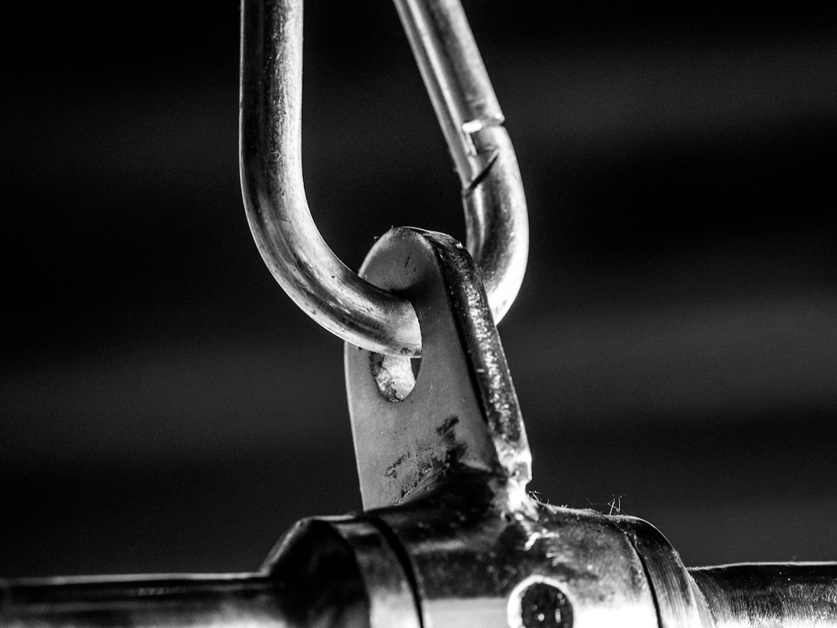
Standard Clevis Pins
Standard clevis pins are headless pivot fasteners engineered to transfer shear loads between overhead line components while relying on cotter retention to prevent rotational loosening under dynamic grid conditions.
The primary operational friction point for utility procurement teams is preventing joint degradation caused by inadequate shear capacity or improper retention methods. Unlike threaded hardware that depends on clamping force, standard clevis pins operate exclusively through direct bearing resistance. This headless configuration enables flush mating with fork terminals, eliminates protrusion hazards, and maintains consistent contact surfaces across connecting eyelets. Selecting pins with verified dimensional tolerances and standardized cotter interfaces ensures structural continuity without introducing tension variability into dynamic line assemblies.
Headless Geometry and Shear Load Distribution
The cylindrical shaft of a standard clevis pin is sized to withstand lateral forces generated by wind oscillation, thermal expansion, and conductor sag. Because the connection relies on single or double shear planes, the pin diameter must align precisely with the applied load matrix. Excessive clearance between the pin shaft and connected eyelets accelerates fretting corrosion and widens play over time, compromising alignment in tension or suspension hardware. Tight manufacturing tolerances around the bearing surface minimize micro-movement while preserving articulation freedom during installation.
Specification Thresholds for Utility-Grade Performance
- Material Composition: Medium-carbon alloy steel (typically C1040 or equivalent) provides the necessary yield-to-tensile balance to absorb impact loads without brittle fracture.
- Shear Rating Baseline: Single-shear capacity generally spans 4.5 kN to 12 kN depending on shaft diameter, requiring dual-shear routing for heavy dead-end or guy wire terminations.
- Corrosion Protection: Hot-dip galvanizing compliant with ISO 1461 delivers a mean metallic coating thickness exceeding 85 microns, outperforming electroplated finishes in humid or coastal grid environments.
- Diameter Tolerance: Production deviations must remain within ±0.5 mm to prevent binding in fork geometries while maintaining uniform load distribution across the shear plane.
Cotter Retention and Anti-Fatigue Protocols
The transverse hole drilled through the shank end functions as the sole mechanical anchor, making cotter pin selection critical for long-term reliability. When correctly sized, the split pin bridges the hole evenly, distributing cyclic stress across the pin wall rather than concentrating it at a single point. Field installation protocols require bending the cotter legs to a minimum 90-degree angle, creating a physical barrier that resists vibration-induced withdrawal. Insufficient leg extension or improper hole alignment introduces lateral play, which accelerates wear at the bearing interface and shortens service life in remote overhead line deployments.

Shouldered Clevis Pins
Shouldered clevis pins anchor the pivot point within the U-bracket fork to eliminate rotational play and axial displacement. The integrated shoulder design redistributes concentrated shear stress across a wider bearing surface while preventing metal-to-metal galling during dynamic grid loading.
Shear Stress Distribution at the Pivot Interface
Standard cylindrical fasteners rely entirely on friction and tight tolerance fits to maintain position under tension. When overhead line conductors experience wind sway or ice accumulation, those unanchored interfaces suffer from localized stress concentration at the contact points. An integrated shoulder acts as a mechanical stop, transferring radial loads away from the pin shank and into the structural fork walls.
This geometric modification ensures that shear forces are distributed evenly across a broader cross-section rather than concentrating at a single circumferential line. Field testing per IEC 120 guidelines consistently demonstrates that shoulder-equipped configurations reduce fatigue failure rates in high-cycle vibration environments. The design effectively converts pure bending moments into controlled compressive loads at the mounting bracket.
Surface Wear Mitigation and Axial Locking
Without a defined shoulder, repeated articulation causes abrasive wear on both the pin shaft and the insulator or clamp eyelet. Metal transfer and micro-galling gradually widen the clearance gaps, compromising alignment and increasing the risk of accidental disengagement. The machined shoulder establishes a fixed reference plane that keeps the fastener seated correctly throughout its service life.
Manufacturing precision directly dictates how tightly the shoulder matches the fork cavity. Automated hot-forging and CNC machining maintain dimensional tolerances within 1mm, guaranteeing consistent contact pressure without inducing binding friction. When paired with post-installation retention like split cotter pins, the shoulder absorbs the primary operational shear while the locking mechanism prevents longitudinal pull-out.
- Bearing Surface Area: Expands by approximately 40% compared to standard smooth shanks, directly lowering PSI contact pressure on mating hardware.
- Corrosion Protection: Hot-dip galvanizing processes compliant with ISO 1461 apply a mean coating thickness exceeding 85 microns, shielding the critical shoulder edge from electrolytic degradation.
- Thermal Expansion Compensation: The fixed axial stop accommodates conductor sag variations caused by temperature swings, preventing cross-arm misalignment without requiring torque recalibration.
Procurement teams evaluating pole line hardware should verify that shoulder dimensions align precisely with utility-specific bracket specifications. Mismatched shoulder heights force installers to rely on excessive shimming or incorrect washer stacks, which defeats the structural purpose of the design. Properly specified shouldered pins streamline assembly speed while maintaining long-term electrical grid reliability.
Operational Impact of Integrated Shoulders
The mechanical advantage of a shouldered design becomes apparent when analyzing long-term maintenance cycles on exposed transmission towers. Conventional unshouldered pins require periodic retightening or replacement once clearance gaps exceed safe operational thresholds. The shoulder configuration inherently maintains alignment stability, significantly extending the interval between scheduled inspections.
Engineers specify shouldered variants for applications where angular flexibility must be maintained without sacrificing axial rigidity. The elevated profile creates a predictable load path that standardizes engineering calculations across multi-span line installations. This consistency simplifies procurement logistics and reduces on-site fabrication errors during large-scale rollout projects.
Frequently Asked Questions
How does shoulder height impact fork alignment?
Shoulder height must match the internal depth of the U-bracket fork exactly. Proper seating ensures the load transfers directly into the bracket base rather than cantilevering off the pin shank, which prevents uneven stress distribution and premature bracket deformation.
Does the shoulder design affect installation speed?
Yes, the fixed axial reference eliminates the need for alignment shims or iterative positioning during assembly. Technicians can slide the pin into place, secure the cotter retention, and complete the connection in a single standardized motion, reducing labor hours per tower.

Threaded Clevis Pins
Threaded clevis pins offer superior resistance to vibrational loosening by utilizing standard nuts for retention, eliminating the maintenance overhead and clearance issues associated with cotter pins.
Nut Retention Versus Cotter Pin Systems
In critical overhead line applications, the method of pin retention is as vital as the pin itself. While standard clevis pins rely on cotter pins or split pins to secure the assembly, threaded clevis pins utilize external threads to accommodate a hex nut, castle nut, or lock nut. This fundamental difference addresses a major procurement pain point: failure due to cotter pin shear or improper installation. Threaded pins provide a higher clamp force and stability, particularly in dynamic load environments where vibration is a constant factor. By engaging the full thread depth with a properly torqued nut, the assembly creates a secure joint that is significantly less prone to working loose compared to a simple shear pin setup.
Threading Specifications and Tolerances
For B2B buyers, the devil is in the thread tolerances. Threaded clevis pins used in pole line hardware are typically manufactured to Unified Fine (UNF) or Unified Coarse (UNC) standards, or metric ISO standards depending on the region of deployment. Unlike general-purpose bolts, these pins often require a specific "Class of Fit" to ensure they mate securely with clevis eyes without introducing play.
- Thread Engagement: Minimum engagement length is typically equal to the nominal diameter of the pin to ensure full tensile strength development.
- Partial vs. Full Threading: Many utility-grade pins feature partial threading to maximize the shear strength of the unthreaded shank section, which is the primary load-bearing area in a clevis joint.
Galvanizing and Thread Integrity
A common failure point in procuring threaded hardware is the conflict between corrosion protection and thread functionality. Hot-dip galvanizing is the industry standard for corrosion resistance, with high-quality specifications requiring a mean coating thickness exceeding 85 microns in compliance with ISO 1461. However, this zinc buildup can alter thread pitch.
Load Security in Vibration-Prone Environments
The primary engineering argument for selecting a threaded clevis pin over a standard clevis pin is security under vibration. In transmission lines, Aeolian vibration and wind loads can cause constant movement. A cotter pin relies on a small bend to retain the pin; if that bend fatigues or the pin shears, the connection fails. A threaded connection, especially when paired with a prevailing torque nut (nylon insert) or a castle nut with a new cotter pin, offers a dual-redundancy that is far more durable. This makes threaded pins the preferred choice for suspension assemblies, dead-end clamps, and other hardware where failure is not an option.
Clevis Hooks and Sling Connections
Clevis hooks function as articulated pivot interfaces between slings and anchor structures, requiring precise load distribution, verified retention locking, and standardized corrosion protection to prevent catastrophic failure under dynamic tension.
Resolving the Rigidity Versus Adjustability Trade-Off
Utility contractors and rigging teams consistently face a critical operational bottleneck when designing pole line tensioning systems: permanent welds versus reliable mechanical links. Traditional welded sling attachments eliminate articulation but demand specialized on-site certification and destroy the host chain during future upgrades. Clevis hooks solve this by utilizing a dedicated clevis fastener system composed of a U-shaped bracket and a precision clevis pin. This mechanical separation ensures the chain is never fused to the hook head, allowing technicians to detach, inspect, or replace rigging components without thermal cutting or re-welding.
The operational advantage becomes immediately apparent during grid maintenance campaigns. Because the hardware establishes a secure, convenient pivot point, installation crews can rapidly realign slings when pole orientations shift or when retrofitting legacy infrastructure. This modularity directly translates to reduced crew exposure time in live work zones and significantly lower logistical costs for bulk procurement.
Retention Locking and Overhead Lifting Compliance
Security at the fork interface dictates overall system safety. The clevis pin must resist shear forces generated by asymmetric loads and continuous wind sway. Industry safety guidelines explicitly state that cotter pin-style clevis hooks are not to be used for overhead lifting applications. Instead, qualified manufacturers engineer these connections with hardened, grade-specified clevis pins paired with standardized split-pins or positive-locking retention sleeves. This configuration prevents vibration-induced loosening while maintaining the angular flexibility required for proper load transfer.
- Pin Shear Rating: Clevis pins must meet or exceed the working load limit of the attached sling, typically validated through rigorous in-house gauge testing per IEC 120 standards.
- Corrosion Resistance: All mechanical interfaces undergo hot-dip galvanizing compliant with ISO 1461, guaranteeing a mean coating thickness exceeding 85 microns to withstand harsh atmospheric exposure.
- Manufacturing Process: Hot-forging is universally preferred over traditional casting for clevis bodies, delivering a continuous grain flow that provides superior tensile strength and impact resistance under sudden shock loading.
Field Serviceability and Inspection Protocols
Maintenance engineering prioritizes components that simplify routine audits. A well-designed clevis mounting system concentrates wear patterns at predictable stress points rather than hiding fractures inside opaque weld zones. Field inspectors focus primarily on bore elongation within the fork prongs and the integrity of the retaining pin mechanism. Because the connection remains fully disassemblable, defective slings can be swapped out instantly without compromising the primary anchor hardware.
Ultimately, selecting the correct clevis hook architecture shifts the maintenance paradigm from reactive repair to predictive replacement. By adhering to strict dimensional tolerances and verified mechanical retention methods, utility operators ensure consistent performance across demanding international tender requirements and extreme environmental deployments.
Clevis Hangers and Brackets
Structural Mechanics and Application
Clevis hangers and brackets function as critical suspension nodes, designed to securely anchor pipes, conduits, and structural rods to flat surfaces or overhead frameworks. Distinct from general fasteners, these components are typically manufactured as solid metal pieces featuring a flat rectangular base equipped with precision-drilled holes for bolts or machine screws. Extending from this base are two parallel rounded wings that form the clevis structure. This U-shaped geometry is engineered to provide a stable cradle for cylindrical loads, allowing for secure attachment while accommodating necessary alignment adjustments during installation.
Manufacturing Integrity: Hot-Forging vs. Casting
For B2B buyers focused on long-term infrastructure reliability, the manufacturing method of the bracket is a primary decision factor. While entry-level brackets are often produced using casting, high-performance specifications mandate hot-forging. Hot-forging aligns the grain structure of the steel, resulting in superior tensile strength and impact resistance compared to the porous nature of cast metals. In demanding environments—such as those requiring high-breaking loads for extreme weather—hot-forged clevis brackets eliminate the risk of fracturing under dynamic stress, ensuring the structural integrity of the suspension system remains intact over decades of operation.
Corrosion Resistance and Coating Specifications
Exposure to elements necessitates rigorous corrosion protection standards. A key indicator of quality is compliance with ISO 1461 for hot-dip galvanizing. Professional-grade specifications typically require a mean coating thickness exceeding 85 microns. This level of galvanization ensures a smooth, bright finish that acts as a sacrificial barrier, preventing rust formation on the base metal even in high-humidity or industrial corrosive atmospheres. Buyers should reject samples with thin or uneven coatings, as these inevitably lead to premature maintenance costs and grid instability.
Precision Tolerances and Quality Assurance
Installation speed and safety depend heavily on dimensional accuracy. Inferior manufacturing often results in misaligned holes or inconsistent fork widths, forcing field crews to modify components on-site—a major liability. High-quality clevis brackets are produced using automated machinery to maintain a strict 1mm tolerance on all critical dimensions. To mitigate supply chain risks, procurement protocols should insist on a 100% double-review inspection process. This means every unit undergoes gauge testing and visual verification twice before packaging, ensuring that the delivered goods match the approved technical drawings and load ratings without deviation.
Conclusion
Pivot joints beat fixed torque fasteners on vibration grids. The U-bodied clearance allows controlled angular movement while cotter retention locks shear stress away from threaded roots. We run mill-certified shear tests across every forged batch. Shoulder geometry dictates failure points far more than thread pitch. Rigid bolted connections fracture under cyclic overhead loads. Switch to shouldered pins for high-cycle infrastructure projects today. Forged steel withstands environmental corrosion better than painted alternatives.
- Verify fork clearance matches your pin diameter before finalizing blueprints.
- Request prototype samples to validate angular flex limits against your load chart.
- Direct design questions to our engineering team for free structural calculations.
Frequently Asked Questions
How are clevis pins manufactured for strength?
High-strength clevis pins typically undergo hot forging to align grain structure with component geometry. This process densifies the metal and eliminates internal voids common in casting methods. Subsequent heat treatment and precision machining guarantee consistent mechanical properties across production batches. Forged components consistently demonstrate higher impact resistance and fatigue endurance than alternative manufacturing techniques.
Which material suits coastal environments best?
Marine-grade stainless steel or heavily galvanized carbon steel perform optimally in coastal conditions. Chloride exposure rapidly accelerates corrosion on untreated metals, making protective coatings essential. Hot-dip galvanization provides a metallurgical bond that withstands salt spray and humidity far better than paint. Selecting the correct alloy directly extends service life in aggressive atmospheric zones.
How to prevent clevis pin corrosion?
Preventive corrosion management starts with selecting appropriate surface treatments during procurement. Galvanizing, zinc plating, or powder coating create physical barriers against moisture and chemical exposure. Regular inspection schedules should monitor coating degradation, especially in high-friction pivot areas. Prompt replacement of compromised components maintains overall system reliability and safety compliance.
When should clevis pins be replaced?
Replacement becomes necessary when pin diameter reduction exceeds five percent of original specifications. Visible cracks, severe galling, or permanent bending indicate structural compromise that cannot be repaired. Fork misalignment also signals excessive wear that will accelerate failure in adjacent hardware. Proactive replacement based on measurable wear thresholds prevents unexpected infrastructure downtime.
Can pin fasteners be reused safely?
Pin fasteners can often be reused if they show minimal wear or deformation. Inspect the shank diameter and fork alignment before reinstallation to ensure proper clearance. Reusing pins that exhibit galling, bending, or thread damage compromises joint integrity and safety. Always replace components that fail dimensional checks rather than attempting field repairs.