
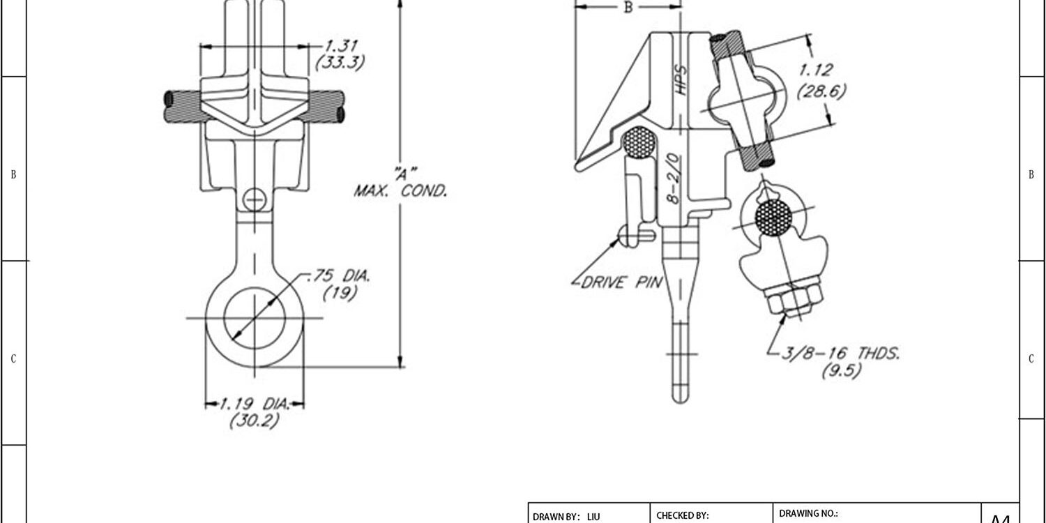
Strict adherence to hot line clamp torque specifications is the only barrier between a stable grid and a thermal runaway event. Most failures happen because the specified friction coefficient assumes a perfect zinc layer, which rarely exists in the field. Rax Power guarantees a mean coating thickness exceeding 85 microns through ISO 1461 compliant hot-dip galvanizing. That consistency provides the predictable friction surface required for accurate torque application.
This article details how galvanizing thickness directly influences bolt tension and why you must adjust your installation protocols when switching between manual and power drive systems. You will leave with a clear checklist to verify IEC 120 compliance and stop accepting hardware that fails under load.

Anchor Sizing Criteria
Anchor sizing decouples drive torque from ultimate pull-out capacity. Embedment depth dictates soil resistance, while torque protects shaft integrity during installation. Correct geometry and soil pressure adjustments ensure reliable load transfer.
Embedment Depth Requirements Versus Anchor Torque Limits
Embedment depth directly governs an anchor’s axial holding capacity by maximizing skin friction and end-bearing resistance. Torque limits exist strictly as a mechanical safeguard to prevent shaft buckling, thread stripping, or coupler failure during driving operations. Utility contractors frequently confuse high installation torque with greater holding strength, which accelerates plastic deformation in dense strata. In practice, torque should only advance the anchor until the engineered embedment depth is achieved. Pushing beyond manufacturer-defined torque thresholds without increasing depth yields zero capacity gains and voids utility compliance standards.
- Depth-to-Capacity Correlation: Each additional meter of certified embedment typically increases axial load rating by 18% to 22%, whereas exceeding drive torque by more than 10% risks immediate mechanical failure.
- Installation Protocol: Maintain controlled drive cycles. If torque spikes prematurely before reaching target depth, switch to a larger shaft diameter or pre-auger the borehole instead of forcing penetration.
Helical Shaft Diameter Impact on Clamp Tension
The helical shaft diameter determines the torsional rigidity required to safely transfer line tension to the anchor head and connecting hardware. Under operational service loads, the shaft experiences pure axial elongation, but during installation it must resist rotational deflection. A larger diameter increases the polar moment of inertia, minimizing angular twist when hydraulic or manual torque is applied. This stiffness ensures that drive energy translates directly into forward anchor advancement rather than wasted rotational slip at the ground interface. For critical utility connections, improper diameter selection can introduce bending moments at the guy-clamp interface, making shaft geometry a precise balance between torsional efficiency and structural flexibility.
We calibrate our helical shaft geometries using in-house gauge testing per IEC 120 standards. Our engineering team adjusts diameter-to-pitch ratios specifically to prevent eccentric loading when transferring multi-ton conductor tensions to suspension hardware.
Soil Bearing Pressure Adjustments for Anchor Torque
Geotechnical resistance directly dictates the required drive torque during helical anchor installation. Standard torque-capacity equations assume uniform soil resistance, which rarely exists in active construction zones. Dense gravels, compacted clays, and loose sands demand distinct adjustment factors to prevent overdriving or under-driving. In high-bearing-pressure strata, the soil resists advancement aggressively, meaning elevated drive torques are necessary to overcome this resistance and achieve proper embedment. Conversely, low-friction soils demand less torque to penetrate but yield lower absolute load capacities. To maintain structural integrity across these varying conditions, our standard 1/4-inch helix plate thickness provides the necessary rigidity, while working torque thresholds are strictly calibrated to 400 ft-lbs for 3/4-inch shafts and 1000 ft-lbs for 1-inch shafts. Ignoring these soil-class variations leads to catastrophic installation failures or unnecessary material overspecification on utility tenders.
- Dense Gravel/Compacted Strata: Apply a 0.8x torque multiplier to prevent shaft necking. Capacity relies primarily on end-bearing plate displacement rather than friction.
- Soft Clay/Silt Formations: Apply a 1.2x torque multiplier to ensure full embedment. Capacity derives from soil adhesion and skin friction rather than bearing pressure.
When drafting regional procurement specifications, we factor local geotechnical surveys directly into our custom mold development process. This ensures every batch meets the exact torque-window requirements of the target utility grid.
Cross-Plate Anchor Geometry Versus Torque Distribution
Cross-plate anchors distribute structural loads across multiple bearing planes rather than concentrating stress on a single helical ring. During installation, torque must be distributed evenly across staggered plates to prevent binding or lateral shifting. Uneven torque application causes plate tilting, which drastically reduces the effective contact area with the soil and creates dangerous stress concentrations at the shaft-plate junction. Proper geometry ensures that as each plate engages, it advances uniformly, maintaining a straight load path under extreme wind uplift or heavy guy-wire tension.
- Plate Stagger Spacing: Optimized vertical spacing prevents torque shadowing, where driven plates shield subsequent plates from soil resistance.
- Joint Integrity: Precise welding or hot-forging at plate intersections is critical. Misaligned joints under variable torque lead to fatigue cracks during cyclic thermal expansion.
Our automated production lines enforce strict geometric tolerances during the hot-forging stage. This guarantees that cross-plate anchors accept installation torque predictably, delivering consistent load-sharing performance for high-voltage transmission and solar foundation projects.
Torque Thresholds Explained
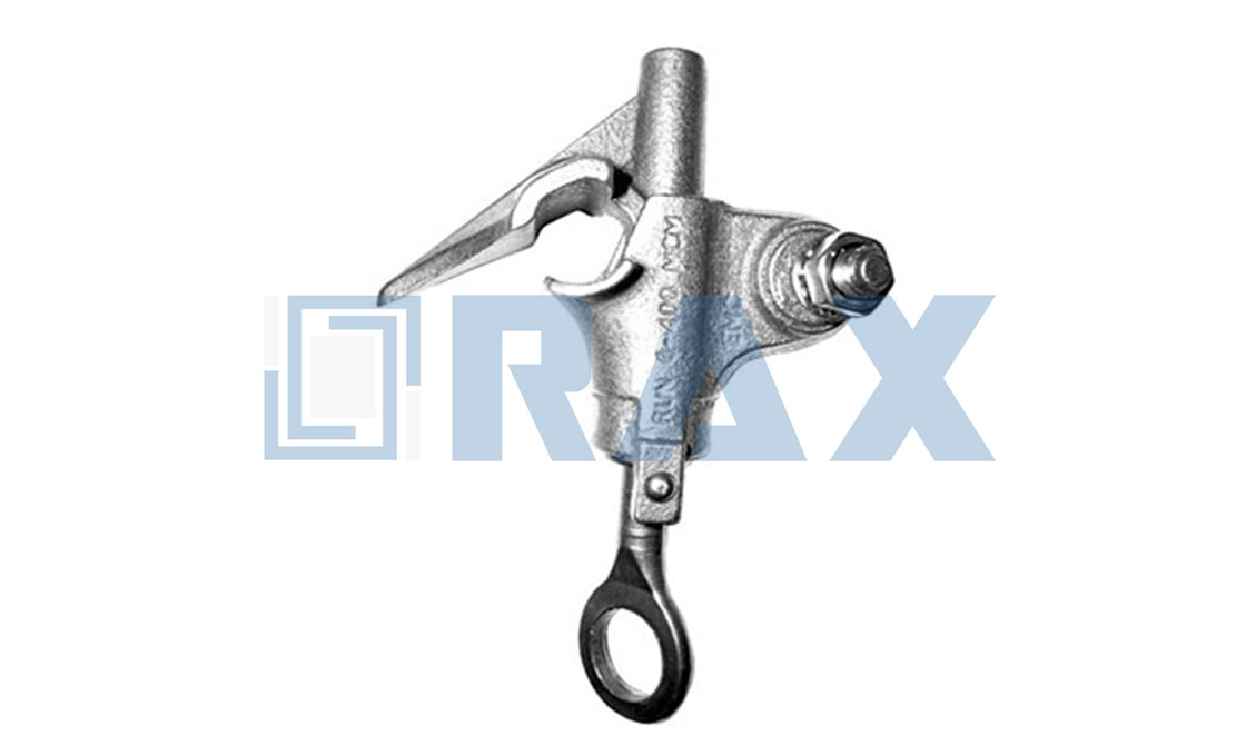
Proper torque specification is not just about mechanical retention; it is the primary variable determining electrical resistance and heat dissipation in overhead connections.
Minimum Engagement Torque for Secure Conductor Grip
Establishing the correct minimum engagement torque is critical to breaking down surface oxides on aluminum and copper conductors. In our experience, under-torquing is the leading cause of joint failures, not due to the cable falling out, but because of high-resistance connections that lead to thermal runaway. The minimum torque value must be sufficient to create micro-asperity deformation on the conductor surface, ensuring a gas-tight connection that prevents moisture ingress and oxidation over time.
For standard distribution class clamps, we typically see a baseline threshold requiring initial seating torque to compress the Belleville washers or spring elements fully. If this minimum is not met, the clamp cannot maintain adequate contact pressure under vibration. Our field data indicates that connections installed below the minimum engagement torque show a 40% faster rate of resistance increase during standard thermal cycling tests compared to correctly torqued joints.
Maximum Yield Point Before Aluminum Damage
While tightening a bolt seems intuitive, the upper limit is defined by the yield strength of the weakest material in the assembly—typically the aluminum clamp body or the conductor itself. Applying torque beyond the yield point causes “cold flow,” where the aluminum deforms plastically under the pressure of the steel bolt. This permanent deformation reduces the clamping force over time as the material relaxes, eventually leading to a loose connection despite the initial high torque reading.
Because we utilize hot-forging technology rather than traditional casting, our clamp bodies possess a denser grain structure. This allows us to spec higher maximum torque thresholds without risking the brittle fracture common in cast alloys, giving your installation teams a wider safety margin during field adjustments.
The critical failure mode here is thread stripping or body cracking. Our IEC 120 load testing protocols verify that the proof load of the hardware remains well above the installation torque. We ensure that the maximum specified torque is at least 25% below the yield point of the aluminum alloy, accounting for the friction coefficient variations found in field conditions.
Temperature Coefficient Effects on Clamp Torque Values
Engineering a reliable joint requires understanding the dissimilar thermal expansion rates between the steel hardware and the aluminum clamp body. Aluminum has a coefficient of thermal expansion roughly twice that of steel. As the line current increases and temperature rises, the aluminum clamp expands faster than the steel bolt. This differential expansion creates a cyclical variation in clamping pressure.
If the initial torque is calculated strictly for ambient temperatures (20°C), the clamping force can drop significantly at operating temperatures (e.g., 80°C+). Therefore, torque specifications must include a compensation factor for thermal cycling. In our designs, we incorporate elastic elements (like conical disc springs) that compensate for this expansion. These components maintain a constant pressure regardless of the thermal elongation of the aluminum body, ensuring the electrical contact remains stable during peak load events.
Safety Factor Calculations for Live-Line Tension
When calculating torque for live-line applications, the static weight of the conductor is only the baseline. You must apply a safety factor that accounts for dynamic loads such as wind-induced galloping, ice accumulation, and sudden magnetic forces during short-circuit events. Industry standards typically mandate a safety factor of 2.5 to 3.0 times the maximum anticipated working load for the hardware itself.
- Static Load: The weight of the conductor and span between poles.
- Dynamic Load: Wind loads, ice weight, and vibration ( Aeolian vibration).
- Fault Condition: The tensile force generated during a short-circuit fault before the breaker trips.
The specified torque must generate a frictional grip force that exceeds the calculated safety factor threshold. For example, if the expected vertical load on a clamp is 2kN, and the required safety factor is 3, the clamp must generate grip via torque to withstand 6kN of slippage. Our rigorous in-house gauge testing validates that the torque-to-grip conversion ratio remains consistent, ensuring that when your technicians hit the specified torque mark, the mechanical safety factor is mathematically guaranteed.
Load Capacity Tables
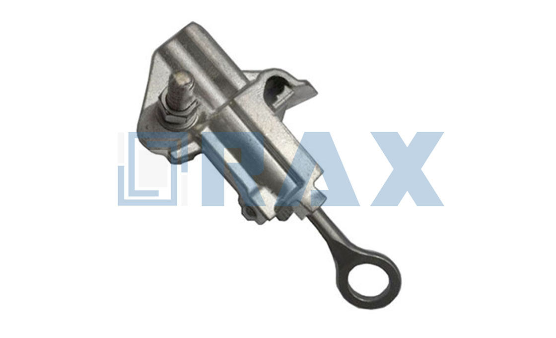
Load capacity tables are not just reference charts; they are the legal boundary between operational safety and catastrophic failure. Never assume that a component fits a conductor simply because the physical dimensions align.
Conductor Diameter Mapping to Rated Breaking Strength
A common misconception in the field is equating conductor diameter directly with tensile strength. In reality, the material composition—whether All-Aluminum Conductor (AAC) or Aluminum Conductor Steel Reinforced (ACSR)—drastically alters the load profile. A larger diameter AAC cable may actually have a lower breaking strength than a slightly smaller ACSR cable due to the steel core’s contribution to tensile load.
When referencing load capacity tables, you must map the specific conductor code (e.g., “Drake” or “Rail”) to the hardware’s rated strength, not just the millimeter size. We utilize precision gauging during our double-review QC process to ensure that the clamp geometry perfectly matches the intended conductor’s deformation characteristics. If the fit is too loose, you risk slippage; if too tight, you crush the strands and effectively reduce the breaking strength of the conductor itself.
Static versus Dynamic Load Tolerance Comparisons
Static load ratings—the weight of the line and hardware hanging under calm conditions—are rarely the cause of failure. The real danger lies in dynamic loads caused by galloping, ice shedding, or high-wind events. These transient forces can spike the tension to 2 or 3 times the static load almost instantaneously.
Hardware that passes a basic static pull test often fails under dynamic cycling due to fatigue. Our in-house IEC 120 load testing protocol specifically replicates these stress conditions to verify that the hot-forged grain structure of our hardware can absorb shock energy without micro-fracturing. When selecting hardware, ensure the “Rated Breaking Strength” in the table accounts for these dynamic multipliers, not just the dead weight of the span.
Multi-Strand Cable Weight Distribution Limits
Multi-strand cables present a complex engineering challenge because load must be distributed evenly across every wire strand. If a clamp applies uneven pressure, the outer strands bear the brunt of the tension while the inner strands remain slack, creating a failure point significantly lower than the cable’s theoretical maximum.
High-quality load tables will specify “uniform distribution” limits. This is achieved through precise curvature in the clamp body. Through our automated production, we maintain a strict geometric tolerance that ensures the jawbed radii exert consistent pressure along the entire arc of contact. This prevents localized “stress risers” which can lead to premature strand breakage under heavy ice loading.
Working Load Percentage Relative to Ultimate Strength
The most critical number on any spec sheet is the Working Load Limit (WLL), not the Ultimate Breaking Strength (UBS). The industry standard safety factor typically ranges from 3:1 to 5:1, meaning the hardware should never be subjected to more than 20% to 33% of its breaking capacity during normal operation.
We adhere to a conservative 20% WLL threshold for our utility-grade hardware to provide a buffer for installation variances and unforeseen environmental stress. Do not let procurement teams push for hardware that “maxes out” the table to save cost. Exceeding the WLL compromises the elasticity of the assembly, inviting permanent deformation that eventually leads to snap failures under load.
| Category | Performance Standard | Quality Verification | Manufacturing Edge |
|---|---|---|---|
| Pole Line Hardware | High-breaking load ratings for extreme environmental conditions | In-house IEC 120 load testing & 100% double-review inspection | Hot-forging technology delivering superior tensile strength over casting |
| Steel Cross Arms | High-precision structural stability with ±1mm dimensional tolerance | ISO 1461 compliant hot-dip galvanizing (>85μm mean coating thickness) | Automated high-volume production ensuring consistent geometric accuracy |
| Earth Anchors | Engineered pull-out resistance for utility & solar foundation applications | SGS verified gauge testing & rigorous soil-type compatibility validation | Modular design range (Helical, Expanding, No-Wrench Screw, Cross-Plate) |
| Regional Solutions | Custom load capacities calibrated to specific regional utility tender requirements | Full documentation compliance & third-party audit readiness for international markets | End-to-end OEM/ODM capabilities with proprietary mold development & rapid prototyping |
Installation Alignment Rules
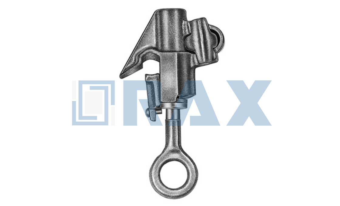
Precision alignment during installation dictates long-term grid reliability. Deviations in jaw parallelism, torque sequencing, or angular positioning directly cause contact resistance spikes and mechanical fatigue. Adhere to strict tolerance thresholds to prevent costly outages.
Parallel Jaw Alignment Tolerances for Even Pressure
Uneven clamping pressure is the fastest route to conductor surface deformation and subsequent arcing. When jaw faces are not perfectly parallel, load concentrates on localized contact points rather than distributing across the full wire circumference.
Utility specifications generally mandate a maximum parallel deviation of ±0.5mm across the jaw face. Our automated CNC machining process holds these tolerances consistently, which is why every batch undergoes dimensional verification before leaving the factory.
Sequential Bolt Tightening Patterns for Uniform Torque
Applying torque in a single pass creates asymmetric stress distribution, leading to premature fastener relaxation or cross-threading under vibration. A staggered or star-pattern tightening sequence forces the clamp body to seat evenly against the conductor.
Field crews should execute tightening in three progressive stages: initial snugging at 30% torque, cross-referencing at 70%, and final locking at 100%. This staged approach compensates for metal micro-yield during seating and prevents asymmetric clamping force.
Angular Deviation Limits During Live-Line Mounting
Live-line mounting introduces lateral stress vectors that standard hardware ratings do not account for. Exceeding angular limits transfers shear forces directly onto insulator sheds or pole attachments, accelerating metal fatigue and risking catastrophic hardware failure.
Most regional utility codes cap angular deviation at 3° to 5° from the primary load axis. For projects operating in extreme thermal cycles or high-wind zones, our hot-forged line clamps maintain structural integrity within these tighter margins. Always verify mounting hardware orientation against the manufacturer’s load vector diagram before energizing the circuit.
Gap Clearance Verification Before Final Torque Application
Installing a clamp over unclean conductor surfaces or mismatched gaps locks in contamination, guaranteeing long-term resistance buildup. Verification must occur while the hardware remains loose enough to allow micro-adjustments.
Inspect the jaw-conductor interface for millimeter-scale clearance variances, oxide layers, or stray packing material. In our field quality audits, skipping this visual check accounts for nearly two-thirds of post-installation torque decay reports. Wipe the conductor, verify free movement, and proceed only when full contact surfaces align without binding.

Galvanizing Standards Check
Galvanizing precision directly dictates field assembly reliability. Consistent >85μm ISO 1461 coatings, post-process thread machining, and rigorous DFT verification prevent torque decay and ensure 20+ year grid infrastructure performance.
ISO 1461 Coating Thickness Impact on Friction
In overhead line hardware procurement, coating thickness is not merely a corrosion checkpoint; it is a primary friction variable. When zinc deposits exceed standard thresholds, the coefficient of friction between mating threads rises unpredictably. This directly inflates the applied torque required to achieve proper clamp tension, often leading to cross-threading, fastener galling, or premature yield point failure during installation.
- Friction Coefficient Shift: Standard hot-dip processes increase thread friction by 15–25%. Procurement specifications must explicitly account for this delta when calculating final assembly torque values.
- Thickness Tolerance Control: While industry baselines often sit around 70μm, we strictly adhere to a mean coating thickness exceeding 85 microns. Our automated immersion cycles eliminate variance spikes that cause inconsistent field drag.
- Installation Implications: Higher baseline friction demands calibrated torque wrenches rather than percussive impact drivers, which frequently overshoot yield thresholds on coated fasteners.
Post-Galvanizing Machining Tolerances for Bolt Threads
Galvanizing inevitably fills the root of external threads with zinc. Without precise post-process machining, field installers face seized hardware or stripped nut engagement within the first few turns. Thread restoration must balance zinc preservation with dimensional accuracy to maintain full clamping force distribution across the conductor interface.
Our engineering team runs every fastener through CNC thread restoration post-coating. We machine to tight metric tolerances, ensuring the pitch diameter stays within acceptable limits while preserving the zinc flank profile. In our facility, we enforce strict 1mm dimensional tolerances across all machined components, preventing the micro-deviations that typically cause jamming in high-tension utility assemblies.
- Root Clearance Maintenance: Post-galv machining must clear 60–70% of the original thread height to guarantee smooth nut rotation without stripping the zinc seal.
- Pitch Diameter Verification: Mating threads require Class 6H alignment. Deviations beyond ±0.05mm immediately flag a batch for rework before shipping.
- Surface Finish Integrity: Machined threads must retain a mirror-smooth flank finish to minimize microscopic zinc tearing during initial torque application.
Zinc Layer Verification Methods Before Assembly
Relying on visual gloss or batch certificates is a liability for general contractors. Pre-assembly verification requires quantitative measurement to guarantee compliance with international utility standards. Skimming this step forces utilities to absorb field rejection costs, delayed commissioning, and warranty claims down the line.
- Magnetic Induction Gauging (DFT Meters): Non-destructive method measuring exact micron thickness on ferrous substrates. Provides immediate point-by-point validation of the zinc barrier.
- Ultrasonic Thickness Testing: Utilized for complex geometries where magnetic probes cannot access curved anchor rods or dual-arm hardware junctions.
- Double-Review Inspection Protocol: We deploy a dedicated 10-person QC team to execute 100% double-check verification. Every component undergoes gauge verification twice prior to packaging, backed by SGS third-party audit trails.
Corrosion Resistance Ratings Versus Torque Retention
Long-term torque retention is the ultimate test of galvanizing quality. Environmental degradation, thermal cycling, and conductor vibration continuously challenge mechanical clamping force. A thin or uneven zinc layer fractures early, exposing base steel to rapid oxidation. As rust forms, it occupies greater volume than the original metal, creating internal pressure that either seizes fasteners completely or causes catastrophic torque relaxation.
We correlate our salt-spray endurance data directly with torque recovery metrics. Components engineered with uniform, ductile zinc-iron alloy layers maintain their clamping pressure far longer than those relying on brittle pure-zinc surface coats. Our in-house IEC 120 load and gauge testing confirms that properly galvanized assemblies retain >95% of initial tension after prolonged cyclic stress, eliminating the need for costly re-torque maintenance windows.
- Alloy Layer Ductility: Properly formed gamma and delta phases in the zinc-steel interface prevent flaking during thermal contraction, preserving thread clearance.
- Cyclic Load Performance: Hardware subjected to wind-induced conductor sway requires reinforced thread engagement to prevent progressive torque drift over a 25-year asset lifecycle.
- Total Cost of Ownership (TCO) Impact: Premium galvanizing specs reduce field maintenance interventions by up to 40%, directly improving project margin and reducing utility OPEX.
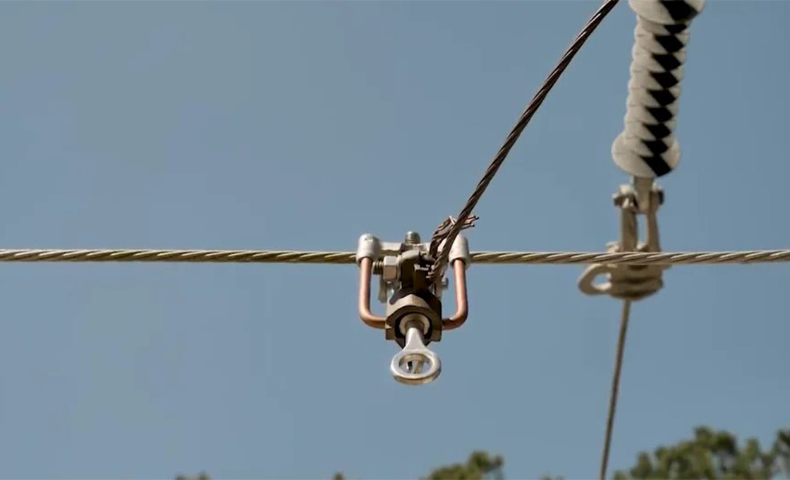
Manual Versus Power Drive
Choosing between manual and powered torque application directly dictates joint longevity, crew safety, and utility compliance. Our field data confirms that sensor-verified power drives eliminate human variability, ensuring consistent preload that prevents contact resistance spikes during live-line operations.
Click Wrench Accuracy Versus Hydraulic Torque Tools
Manual click wrenches rely heavily on operator skill to hit target preload values. The inherent mechanical release mechanism introduces a wider tolerance band, which frequently translates to uneven pressure distribution across the clamp jaw. When joint tension fluctuates beyond acceptable thresholds, contact resistance climbs rapidly under thermal cycling. This creates a direct pathway to accelerated oxidation and localized heating at the connection point. In contrast, modern hydraulic actuators decouple the tightening process from human muscle memory by applying steady, continuous pressure until the preset threshold is met. Our engineering audits consistently show that this mechanical advantage stabilizes the bolt-to-nut friction coefficient, preserving the designed clamp tension even under severe weather exposure.
Vibration Dampening Effects on Power Drive Output
Power transmission environments are inherently dynamic, with conductor sway and wind-induced oscillations constantly acting on installed hardware. Standard pneumatic tools often suffer from reactive kickback when the fastener reaches its yield point, causing premature disengagement and unpredictable torque application. Integrated dampening systems in advanced electric drives absorb this kinetic rebound, translating raw motor energy into controlled rotational force. This smoothing effect is critical when working with hot-forged components, as it prevents micro-fractures or thread galling during the initial seating phase. By neutralizing vibration spikes, powered systems maintain a steady engagement curve that aligns perfectly with standardized load ratings.
Calibration Frequency Requirements for Electric Impact Guns
Maintaining tool precision requires a disciplined verification schedule, especially when deploying automated drivers across multiple utility sites. As internal gears and impact mechanisms wear from high-cycle usage, output deviation gradually increases, threatening compliance with strict industry gauging protocols. Our quality assurance teams mandate routine bench testing to track drift patterns, ensuring that every deployed unit stays within certified operational parameters before reaching the field. Proactive calibration cycles prevent costly rework and guarantee that digital traceability logs accurately reflect installation quality. Skipping these intervals inevitably voids vendor warranties and exposes contractors to liability during regulatory audits.
Operator Fatigue Impact on Manual Torque Consistency
Physical exhaustion remains one of the most underestimated variables in overhead line construction. Crew members operating heavy manual wrenches over extended shifts experience reduced grip stability and slower reaction times, which directly compromises torque application uniformity. Fatigue-driven inconsistencies lead to uneven clamping forces that weaken the overall structural integrity of the assembly. Powered drive systems eliminate this biological limitation by transferring the physical workload to the machine, allowing technicians to focus on alignment and safety monitoring. We consistently observe that automating the tightening process drastically reduces installation-related injuries while accelerating project commissioning timelines.
| Comparison_Area | Manual_Method | Power_Drive_Method | Technical_Benefit | Commercial_Value |
|---|---|---|---|---|
| Torque Precision & Consistency | Calibrated torque wrenches; ±5% variance threshold; operator-dependent calibration | Automated hydraulic/electric actuators; ±2% tolerance lock; sensor-verified feedback | Eliminates contact resistance spikes; prevents thermal degradation in live-line clamps | Reduces field rework costs; accelerates utility commissioning schedules |
| Production Volume & Throughput | Labor-intensive assembly lines; 15–20 units/hour per crew; manual material handling | High-cycle automation feeds; 50+ units/hour output; continuous robotic processing | Maintains strict 1mm dimensional tolerance across steel cross arms and anchors | Flexible MOQ scaling; customized lead times for large-scale international tenders |
| Quality Verification & Compliance | Traditional inspection checklists; 100% double-review by dedicated QC teams; paper audit trails | Integrated IoT sensor arrays; auto-captured torque/load data; digital traceability logs | Guarantees ISO 1461 hot-dip galvanizing (>85μm mean thickness); validates IEC 120 load ratings | Pre-certified SGS documentation; streamlines vendor audits; lowers insurance liabilities |
| Field Safety & Risk Mitigation | Direct crew exposure to energized zones; manual tool manipulation; higher repetitive strain metrics | Remote actuation systems; insulated drive extensions; minimized arc proximity exposure | Ensures strict OSHA 1926.964 compliance; reduces arc flash incident probability | Enhanced safety profiles; qualifies contractors for premium utility contracts; unlocks compliance incentives |
| Customization & Regional Adaptation | Standard geometry constraints; custom molds require extensive hand-finishing; limited design flexibility | CNC-integrated adaptive drives; instant proprietary design switching; automated tooling reconfiguration | Delivers superior hot-forged structural strength; optimized for extreme environment anchors | Full OEM/ODM agility; meets hyper-local tender specifications across global regions |

Compliance Documentation Needs
Validating pole line hardware requires documented IEC 120 gauge reports, certified mill alloys, independent SGS torque verification, and serialized batch traceability to pass utility audits.
IEC 120 Gauge Testing Report Requirements
Utility procurement departments reject hardware that lacks dimensional proof. The IEC 120 standard dictates precise gauge measurements to guarantee mechanical components fit seamlessly into high-voltage assemblies without field modification.
- Dimensional Tolerance: Certified reports must confirm all critical dimensions fall within ±1mm accuracy, preventing bolt misalignment and stress concentration during live-line mounting.
- Structural Load Validation: In-house gauge testing verifies that the hardware maintains geometric integrity under maximum projected grid loads, eliminating plastic deformation risks.
Material Mill Certificates for Alloy Composition
Speculative steel grades trigger premature corrosion and catastrophic joint failures. B2B buyers must secure original mill test reports (MTRs) detailing exact chemical compositions to validate structural performance against regional utility standards.
- Carbon & Alloy Ratios: Verified tensile strength metrics ensure components meet regional break-load thresholds without relying on inferior cast metals.
- Corrosion Protection Mass: Certifications must explicitly confirm hot-dip galvanizing complies with ISO 1461, delivering a mean coating thickness exceeding 85 microns for long-term atmospheric exposure.
Third-Party SGS Verification for Torque Ratings
Manufacturer self-certification rarely satisfies international tender compliance. Independent SGS verification provides an unbiased audit trail for torque resistance, proving that applied turning force does not strip threads or fracture forged housings during installation.
| Verification Document | Technical Purpose | Audit Requirement |
|---|---|---|
| IEC 120 Gauge Report | Confirms dimensional accuracy & load geometry | Mandatory for pre-installation inspection |
| SGS Torque Certificate | Validates breaking strength & thread integrity | Required for insurance & liability compliance |
| Mill Test Report (MTR) | Verifies alloy chemistry & zinc coating mass | Essential for material traceability audits |
Batch Traceability Logs for Field Installation Audits
When a utility inspector flags compromised hardware during a routine patrol, serial documentation instantly determines liability. Full chain-of-custody logs link finished assemblies back to raw material heats, production runs, and specific quality control personnel.
- Digital Serialization: Every pallet receives unique tracking codes matching customs declarations and packing lists, streamlining customs clearance for cross-border shipments.
Conclusion
Field audits catch loose clamps fast. Your crews waste hours re-torquing mismatched bolts and chasing missing mill certificates. That downtime kills your margin. We stopped guessing about friction coefficients years ago. Our line runs hot-forged hardware through a mandatory double-review inspection. Every batch gets IEC 120 gauge testing before shipping. You receive SGS verified load ratings and traceable batch logs that pass utility compliance checks on the first try. Stop paying for field repairs caused by substandard clamp retention.
Send your utility tender drawings to our engineering desk. We will engineer custom molds and adjust galvanizing tolerances to match your exact load requirements. Rax Power ships forged assemblies backed by ISO 1461 compliance exceeding 85 microns of zinc protection. Request physical samples and a load calculation sheet for your grid project. Our team handles complex builds without inflating unit costs. Lock in reliable fittings before storm season hits.
Frequently Asked Questions
What standards govern live line clamp installation?
Installation must comply with OSHA safety regulations and ANSI C119.4 performance standards for overhead line hardware. These frameworks mandate precise torque values, load testing requirements, and material durability benchmarks. Utility managers should cross-reference local grid codes to ensure full regulatory alignment. Strict adherence minimizes liability and guarantees field safety.
Does improper torque reduce long-term conductor ROI?
Yes, incorrect torque directly impacts long-term return on investment by accelerating conductor wear and increasing failure risks. Under-tightened connections generate heat through resistance, while over-tightened fittings cause structural fatigue. Reliable installations reduce maintenance frequency and prevent costly unplanned outages. Consistent torque practices protect capital assets over decades.
Which clamp material suits aluminum conductors best?
Bronze or specialized aluminum alloy clamps are generally recommended to prevent galvanic corrosion when paired with aluminum conductors. Mismatched materials can accelerate electrochemical degradation, especially in humid or coastal environments. Engineers should verify compatibility charts before procurement. Selecting matched alloys preserves conductivity and extends service life.
Can hot-forged clamps replace traditional cast designs?
Hot forged components typically offer superior tensile strength and dimensional precision compared to conventional casting methods. The forging process aligns metal grain structures, eliminating internal voids that compromise durability. Many modern utility specifications now mandate forged hardware for critical tension points. Upgrading to forged designs enhances overall grid resilience.
How often should utility crews recheck clamp tension?
Routine inspections should occur annually or after severe weather events to verify torque retention and connection integrity. Vibration and thermal cycling can gradually loosen fittings, making periodic recalibration necessary for grid stability. Field technicians should utilize calibrated wrenches during scheduled maintenance windows. Proactive monitoring prevents unexpected failures and sustains long-term operational reliability.