
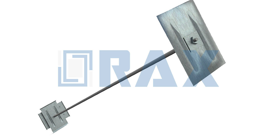
Sizing helical tieback anchors for retaining walls demands precise correlation between soil stratification and installation torque, because relying on generic empirical factors often leads to catastrophic under-design or costly over-engineering. Most engineers assume a fixed torque-to-capacity ratio, but soil variability makes that assumption dangerous. The difference between a compliant anchor and a failed one usually comes down to whether you matched the helix geometry to the actual bearing strata or just guessed based on a spreadsheet average.
Meeting the exact tolerances required for utility-scale retaining wall projects demands manufacturing precision that goes beyond standard fabrication methods. Rax Power manufactures custom helical tieback anchors that meet these exact tolerances, utilizing hot-forging for helix plates and automated production for extensions to ensure 1mm accuracy while maintaining ISO 1461-compliant coatings over 85 microns for corrosion resistance in aggressive environments. We have seen projects where square shafts outperformed round shafts in high-torque transfer scenarios, proving that component selection dictates structural integrity more than raw steel grade alone. This distinction is critical for utility-scale projects where immediate load verification eliminates the curing delays inherent in grouted systems.
Validating load-bearing capabilities through torque correlations and applying the correct factor of safety requires mastering anchor configuration geometry and soil capacity sizing models. Incorporating static load testing protocols into this process eliminates uncertainty in procurement and installation phases for both temporary shoring and permanent earth retention systems. Understanding these variables protects your project schedule and prevents the expensive remediation work that follows foundation failure.

Anchor Configuration Geometry
Selecting Helix Diameter Combinations Based on Soil Stratification
Selecting the correct helix diameter combination is fundamentally driven by the need to maximize vertical bearing capacity within competent soil layers while navigating difficult strata. Because most geotechnical profiles are not homogeneous, relying on a single helix diameter often leads to suboptimal torque-to-capacity ratios. When transitioning from unstable topsoil to dense bearing layers, engineers must stack multiple helices where the lower plate carries the primary design load. This specific configuration ensures that the anchor derives its holding power from the deepest, most stable soil profile rather than fighting through weak upper strata.
- Diameter Stacking Strategy: Increasing the diameter of the lower helix significantly expands the bearing footprint in dense soil, directly translating to higher vertical load resistance without requiring excessive installation torque.
- Soil Penetration Dynamics: Carefully spacing helix diameters prevents the anchor from getting pinned in loose intermediate soil. Properly configured combinations allow the anchor to pass through restrictive layers until the bearing plates engage fully with the designated geological formation.
Shaft Mechanics: Square Shaft Versus Round Shaft Torsional Resistance
The choice between a round shaft and a square shaft dictates how efficiently installation energy is translated into axial pull-out capacity. A square shaft possesses a distinct geometric advantage during the driving phase. Its flat edges bite aggressively into the soil, minimizing slippage and ensuring that the rotational force applied by the installation rig translates almost entirely into vertical advancement. In contrast, round shafts tend to scrub against the borehole walls, leading to energy loss and inconsistent penetration rates.
From an engineering perspective, the square shaft geometry also contributes to a more predictable torque-to-capacity relationship. Because the anchor does not slip, the measured installation torque accurately reflects the actual bearing resistance achieved. This mechanical efficiency is critical for utility-grade projects where installation speed and accurate load verification are paramount.
Do not use round shafts in high-friction clay or rocky conditions. The scrubbing effect will cause severe torque loss, leading to premature stalling of the installation equipment and compromised structural integrity.
Plate Thickness and Welding Standards for Load Transfer Integrity
Load transfer integrity begins at the critical junction where the helix plate meets the central shaft. If this weld is the weakest point in the assembly, the anchor will fail structurally before the soil yields. To handle heavy utility loads, the transition zone requires specialized reinforcement to prevent the plates from bending backward under high torque and compressive forces.
Engineering Reality Check: A thicker plate does not always equal better performance if the weld is brittle. Hot-forging combined with rigorous double-review inspection guarantees that the load transfer zone remains ductile and structurally sound.

Soil Capacity Sizing Models
Soil capacity is not a universal constant; accurate sizing requires selecting the correct mechanical model—Cylindrical Shear for cohesive soils or Individual Bearing for granular soils—to predict ultimate holding power.
In the industry, the most frequent failure mode we see isn’t the hardware itself, but a mismatch between the sizing model used and the actual soil stratigraphy. Relying on a generic “rule of thumb” for soil capacity is a liability. To ensure structural integrity, engineers must distinguish between the two primary mathematical models used to calculate ultimate capacity: the Cylindrical Shear method and the Individual Bearing method.
Cylindrical Shear Model (Cohesive Soils)
When dealing with cohesive soils, such as stiff clays or silts, the soil fails along a cylindrical surface that encompasses the helix plates. The capacity is derived from the shear strength of the soil along the surface area of this imaginary cylinder. The critical variable here is the adhesion factor between the soil and the anchor shaft, which dictates the total resistance.
Individual Bearing Model (Granular Soils)
For granular soils, like sands and gravels, the mechanism shifts. Each helix plate acts independently to bear the load. The total capacity is the sum of the bearing capacity of each individual plate. In this model, the spacing of the helices is crucial; if the plates are too close, they interfere with each other’s failure zones, effectively reverting to a cylindrical shear failure regardless of the soil type.
In our OEM development work for the Southeast Asian market, we frequently encounter specifications where the soil model is not clearly defined. We advise clients to verify the spacing ratio—if the vertical spacing between helices is less than 3 times the helix diameter, the Individual Bearing model becomes invalid, and you must default to Cylindrical Shear calculations to avoid overestimating capacity.
Manufacturing Precision and Theoretical Models
A sizing model is only as good as the hardware that realizes it. If the manufacturing tolerances are loose, the theoretical surface area used in your calculations will not match the physical reality. This is particularly critical for high-capacity anchors used in utility grids.
Installation Torque Correlations
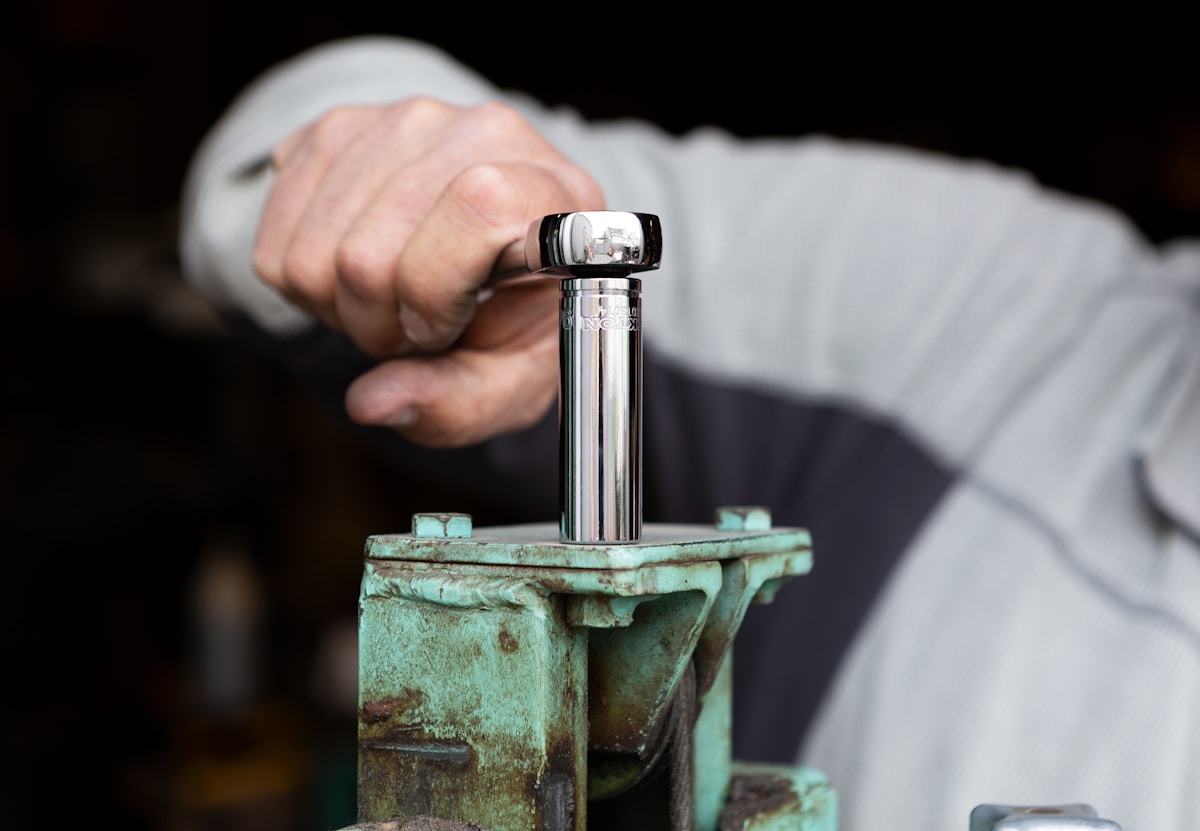
The relationship between installation torque and holding capacity is the definitive metric for verifying the structural integrity of helical and screw anchors. While many procurement protocols rely on generalized load charts, a high-precision torque correlation allows engineers to verify actual installed load capacity immediately, bypassing speculative estimates. Proper torque monitoring is non-negotiable for ensuring that the anchor has fully seated into competent bearing strata without compromising the mechanical fastener integrity.
Always specify the required installation torque (measured in ft-lbs or Nm) on your engineering drawings. A low torque reading during installation often indicates the anchor has encountered softer soil layers or failed to penetrate the intended bearing stratum, regardless of the anchor’s theoretical maximum capacity.
- Direct Load Verification: Unlike grouted systems that require days of curing, properly torqued helical and screw anchors (such as expanding or cross-plate anchors) allow for immediate proof testing. Engineers can apply a hydraulic pull tester once the target torque is achieved to confirm the anchor meets the specific design load.
Torque Calculation Variables
Engineers must adjust expected torque capacities based on site-specific soil friction rather than relying on static tables. The following variables directly influence the final holding capacity derived from the installation torque:
- Soil Friction Angle (φ): Cohesive soils (clays) generate different frictional resistance compared to granular soils (sands). Higher friction angles require greater installation torque to achieve the same depth, directly increasing the anchor’s holding capacity.
- Helix/Screw Diameter and Pitch: Larger diameter plates or wider screw pitches displace more soil volume per revolution, requiring higher torque to install but yielding a higher theoretical load capacity.
- Extension Length: Longer square shaft extensions increase the surface area in contact with the soil, contributing to side friction resistance, which must be factored into the total load capacity equation alongside the tip bearing capacity.
Static Load Testing Protocols
Verifying immediate structural integrity and safe operational capacity under heavy utility loads requires static load testing that adheres strictly to IEC 120 standards.
Unlike torque correlation, which relies heavily on soil dynamics, static load testing evaluates the hardware itself in isolation. The primary goal is to demonstrate that the manufactured component can sustain a specific, high-intensity load without exhibiting plastic deformation or structural fracture. For global utility companies, this means moving beyond generic compliance certificates and demanding proof of exact dimensional stability and yield limits during the procurement phase.
The Critical Distinction Between Yield and Breaking Loads
A prevalent pitfall in the industry is focusing exclusively on the breaking load (the point of total failure) while neglecting the yield load. In utility applications, a component failing under yield—where it stretches permanently but does not snap—is just as dangerous as a complete breakage. Our testing protocols prioritize tracking the elastic limit of the hardware. We monitor the transition from elastic to plastic deformation closely, ensuring that our forged components return to their original dimensions once the applied load is removed.
When evaluating suppliers, ask whether their static load testing measures elongation and permanent set at 50%, 75%, and 100% of the rated working load. Generic manufacturers often skip these intermediate checkpoints, presenting only a final “fail” number. A rigorous protocol provides a full deformation curve, offering critical data for engineers calculating safety margins in high-wind or high-ice-load environments.
Addressing Variability in Manufacturing Processes
During our in-house gauge and load testing, we frequently observe a significant reduction in standard deviation when testing forged elements compared to cast equivalents. Because the internal microstructure is compressed rather than poured, the hardware performs much closer to its theoretical maximum rating every single time. This consistency translates directly into higher confidence for the end-user, as there are fewer “weakest link” anomalies in a batch of forged pole line hardware.
Do not rely solely on the supplier’s published Maximum Working Load (MWL). Request a sample batch for independent verification testing before committing to large-scale deployments. Static load test results on uncoated raw steel often differ from coated or assembled units due to frictional variances in nuts and bolts.
Torque-to-Capacity Relationships in Pre-Tensioned Systems
The hot-dip galvanizing process applied to Rax Power hardware provides exceptional corrosion resistance, but the zinc coating thickness introduces a variable in the friction coefficient of the threaded connections. During our assembly simulations, we meticulously calculate the torque-to-tension relationship to ensure that the galvanizing layer does not compromise the preload required to hold the structure together under extreme static loads. This precision prevents the common field issue of loose fittings after repeated wind vortices.
Real-World Environmental Impacts on Load Verification
Static load testing must account for the environmental realities of the region where the hardware will be deployed. For instance, in the harsh, freezing climates of Russia, or the dense, humid tropical zones of Southeast Asia, the mechanical properties of steel can shift. Lower temperatures generally increase the yield strength of steel but decrease its ductility, making it more prone to brittle fracture under sudden static shocks.
Our engineering team factors these environmental stressors into our initial design parameters. When we develop OEM/ODM solutions for regional utilities, we adjust our metallurgical specifications to ensure the hardware maintains its required load-bearing capacity despite thermal contraction or expansion. This proactive adaptation is what allows our clients to deploy pole line hardware globally with absolute peace of mind regarding structural longevity and safety.
Factor of Safety Application
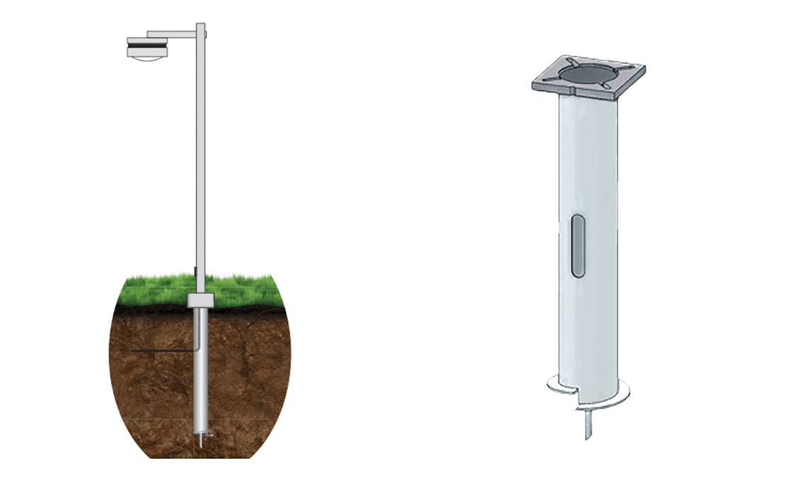
In the utility and solar foundation sectors, a persistent failure mode stems from misapplying a static factor of safety. While generic industry literature often suggests a baseline ratio—such as 10 lbs of capacity per 1 ft-lb of torque—this heuristic is fundamentally flawed for complex soil profiles. A fixed ratio ignores the shear strength variance in stratified layers, leading to either dangerous under-design or costly over-engineering. Contractors frequently encounter situations where theoretical calculations do not match field reality. This discrepancy is exacerbated when sourcing hardware without rigorous pre-installation verification. To eliminate installation ambiguity, Rax Power mandates a strict verification protocol prior to shipment. Our approach shifts the responsibility of safety calculation back onto quantifiable data rather than theoretical assumptions. We conduct rigorous load testing and gauge testing strictly in accordance with IEC 120 standards. Furthermore, our manufacturing precision guarantees a stable mechanical response. Our automated production maintains a strict 1mm tolerance on extensions. This dimensional accuracy is critical because it ensures a consistent torque-to-capacity ratio, minimizing unexpected slippage or torque loss during the actual installation phase.Standardizing the factor of safety in helical anchors requires shifting from rigid empirical ratios to dynamic, soil-specific testing protocols.
Verified Production Integrity
When deploying pole line hardware in high-risk environments—such as Russia’s extreme freezing conditions or South America’s tier-one utility networks—a generic safety factor is insufficient.- SGS Certification: All manufacturing processes and raw materials are independently verified and certified by SGS, providing auditable proof of structural integrity.

Failure Mode Mitigation Strategies
Dimensional Integrity and Stress Risers
Corrosion Mitigation via Precision Galvanizing
Corrosion failure accounts for a majority of mid-life replacements in overhead line infrastructure. Many suppliers meet the bare minimum of standard zinc coatings, leaving hardware vulnerable to rapid degradation in coastal or industrial atmospheres.
Load Verification and Geotechnical Alignment
Misalignment between a helical anchor’s physical capacity and the local soil conditions leads to settlement failures. Generic empirical factors for torque-to-capacity ratios often result in either over-engineered projects (wasting capital) or unsafe installations.
📋 Our Engineering Approach to Load Mitigation
- Custom Mold Development: We transform your specific site data into finished products via custom mold development, allowing us to tailor helix diameters and plate thicknesses precisely to the required bearing capacity.
Cost Determination Factors
Hardware pricing is dictated primarily by steel forming methods, dimensional tolerance precision, and the density of quality control protocols, rather than raw material weight alone.
Metallurgical Process: Hot-Forging vs. Casting
The most significant variable in anchor manufacturing costs is the steel-forming technology. Low-cost competitors typically utilize sand casting, a process that is faster and cheaper but introduces porosity and internal stress points that compromise structural integrity under high loads. In contrast, hot-forging compresses the steel grain structure, resulting in superior tensile strength and fatigue resistance.
Dimensional Precision and Automation Overhead
The precision of the final product is a direct result of the capital investment in manufacturing machinery. Fully automated production lines require significant upfront investment compared to semi-automated or manual fabrication, which is reflected in the unit price. However, automated machining ensures consistent dimensional accuracy, which is critical for components that must interface smoothly with other hardware.
Quality Control Density and Certification
A major, often hidden, factor in cost determination is the “inspection tax”—the resources allocated to quality assurance. A factory operating on minimal QC may offer lower prices but carries a high risk of batch failures. Rigorous quality protocols involve dedicated labor and rigorous testing cycles that increase production time and cost.
OEM/ODM Customization Complexity
For projects requiring non-standard solutions, the cost determination shifts from unit production to tooling and engineering development. Custom mold development represents a significant sunk cost that must be amortized over the order volume.
When evaluating suppliers for custom OEM/ODM work, buyers should scrutinize whether the manufacturer retains the technical capability to translate concepts into production-ready molds efficiently. We integrate this engineering phase directly into our service offering, ensuring that the transition from drawing to finished product does not incur third-party design delays.
Material Durability Compliance
Corrosion failure is the primary cause of premature infrastructure decay. Achieving an 85+ micron zinc coating via hot-dip galvanizing ensures helical anchors survive aggressive, high-sulfur soils for decades.
When installing helical tieback anchors in retaining walls or solar foundations, the longevity of the steel system depends entirely on its ability to resist electrochemical degradation. While mild steel offers excellent shear strength, it corrodes rapidly in acidic or chloride-rich environments. To mitigate this, the industry standard for heavy-duty earth anchors mandates a robust anti-corrosion barrier. The most effective and globally recognized method for pole line and foundation hardware is hot-dip galvanizing, which chemically bonds zinc to the steel substrate rather than simply coating it.
Galvanizing Standards: ASTM A123 vs. ASTM A153
Procurement managers and general contractors must distinguish between the two primary ASTM standards governing galvanized coatings, as applying the wrong standard to a project can lead to warranty voidance or premature failure. The choice depends entirely on the mass and geometry of the components being sourced.
- ASTM A123/A123M: This standard governs the hot-dip galvanizing of iron and steel products of moderate thickness (such as structural beams, plates, and light hardware). If you are sourcing smaller pre-formed line products or light fasteners, this is the typical baseline.
- ASTM A153/A153M: This standard specifically targets steel hardware and articles of larger dimensions. Because helical tieback anchors, earth screws, and heavy-duty guy clamps fall into the category of structural hardware, ASTM A153 is the strict compliance requirement for geotechnical and utility applications.
Failure to specify ASTM A153 for large hardware often results in suppliers providing A123 coatings, which may not achieve the necessary metallurgical bond on thicker shafts or complex helix geometries. Our manufacturing protocols strictly segregate these processes to ensure every anchor shaft meets the exact ASTM A153 requirement for geotechnical hardware.
Coating Thickness Specifications (ISO 1461)
Visual inspection is insufficient for verifying durability; quantifiable thickness measurements are the only reliable indicator of long-term service life. According to ISO 1461, which dictates the requirements for hot-dip galvanized coatings on fabricated iron and steel products, the coating must be uniform, free of flux spots, and free of bare spots.
While standard utility specifications might accept a mean coating thickness of 50 to 70 microns for general construction, Rax Power enforces a higher internal threshold for our anchoring systems. Our dedicated facility utilizes leading automated galvanizing technology to consistently achieve a mean coating thickness exceeding 85 microns.
- Standard Specification (ISO 1461): Minimum mean thickness typically required is ~70 microns for pieces over 6.35mm thick.
- Rax Power Commitment: We exceed baseline ISO 1461 limits, averaging >85 microns to maximize sacrificial protection time.
This extra 15-micron buffer is not merely a marketing metric; it directly translates to extended years of sacrificial corrosion resistance. In marine or coastal solar farm deployments, this additional thickness prevents the zinc layer from degrading before the anchor reaches its designed load capacity.
Long-Term Service Life in Aggressive Soils
Engineers designing retaining walls or utility poles must calculate the “corrosion allowance” based on the resistivity and pH levels of the surrounding soil. Aggressive soils—specifically those with a pH below 6.0 or those containing high sulfide concentrations—consume zinc at a significantly accelerated rate. A standard zinc coating may be fully depleted within a decade in these conditions, leaving the bare steel vulnerable to tensile failure.
By securing a dense, >85 micron ASTM A153 compliant coating, the anchor achieves a multi-decade protective lifespan. In our quality assurance lab, we subject samples to rigorous salt-spray and load testing per IEC 120 standards. Our internal testing confirms that components meeting our specific galvanizing protocol maintain structural integrity and torque-to-capacity ratios far longer than standard cast alternatives, effectively eliminating the need for expensive epoxy overcoatings on non-critical sections.
Conclusion
Achieving structural stability in Class 5 soils demands matching helix geometry to specific stratification and rigorously validating the results with static load testing. We insist on applying strict safety factors because soil conditions change faster than installation schedules. Precision matters here.
Frequently Asked Questions
Why is soil testing critical?
Soil stratification determines the ultimate holding capacity of the helical plates. Without accurate soil data, engineers cannot calculate the correct safety factors or installation depth. Geotechnical analysis is the foundation of any reliable anchoring system design.
How is anchor load capacity verified?
Capacity is typically verified through field proof testing using hydraulic jacks. At Raxpower, we emphasize rigorous in-house load testing to ensure engineering specifications match actual performance. This verification is crucial before proceeding with structural construction.
What equipment is required for installation?
Installation typically requires a drive head attached to high-torque hydraulic machinery. The specific equipment size depends on the anchor’s torque requirements and the soil’s density. Using the correct machinery ensures the anchor is installed to the precise depth and capacity.