
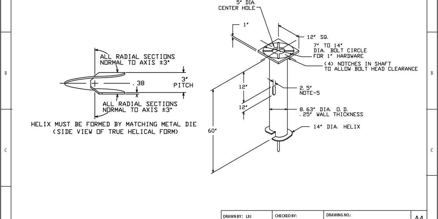
Eliminating weather-dependent curing windows allows contractors to deploy helical support systems directly into variable ground profiles. These systems thread into unstable soil layers without displacing material, utilizing high-strength forged shafts and precision-welded helix plates. Instead of relying on static ratings, ultimate load resistance—typically ranging from 10 kN to 800 kN for standard configurations—is determined through torque-to-capacity correlation. Rax Power engineering standards calibrate these components to verified torque readings, ensuring accurate load transfer without exceeding geotechnical limits. Engineers prioritize these real-time metrics over theoretical models to account for shifts between the office and the dig site, as final drive readings confirm actual bearing strata engagement before structural assembly begins.
You will learn exactly how to match helical pile geometry to local soil density, track installation torque for verified load ratings, and navigate unexpected subsurface obstructions without damaging the shaft. We also break down how different industrial projects select configurations based on lateral resistance requirements and corrosion protection standards. Mastering these installation variables eliminates foundation rework and keeps heavy construction timelines intact.
What Are Helical Piles?
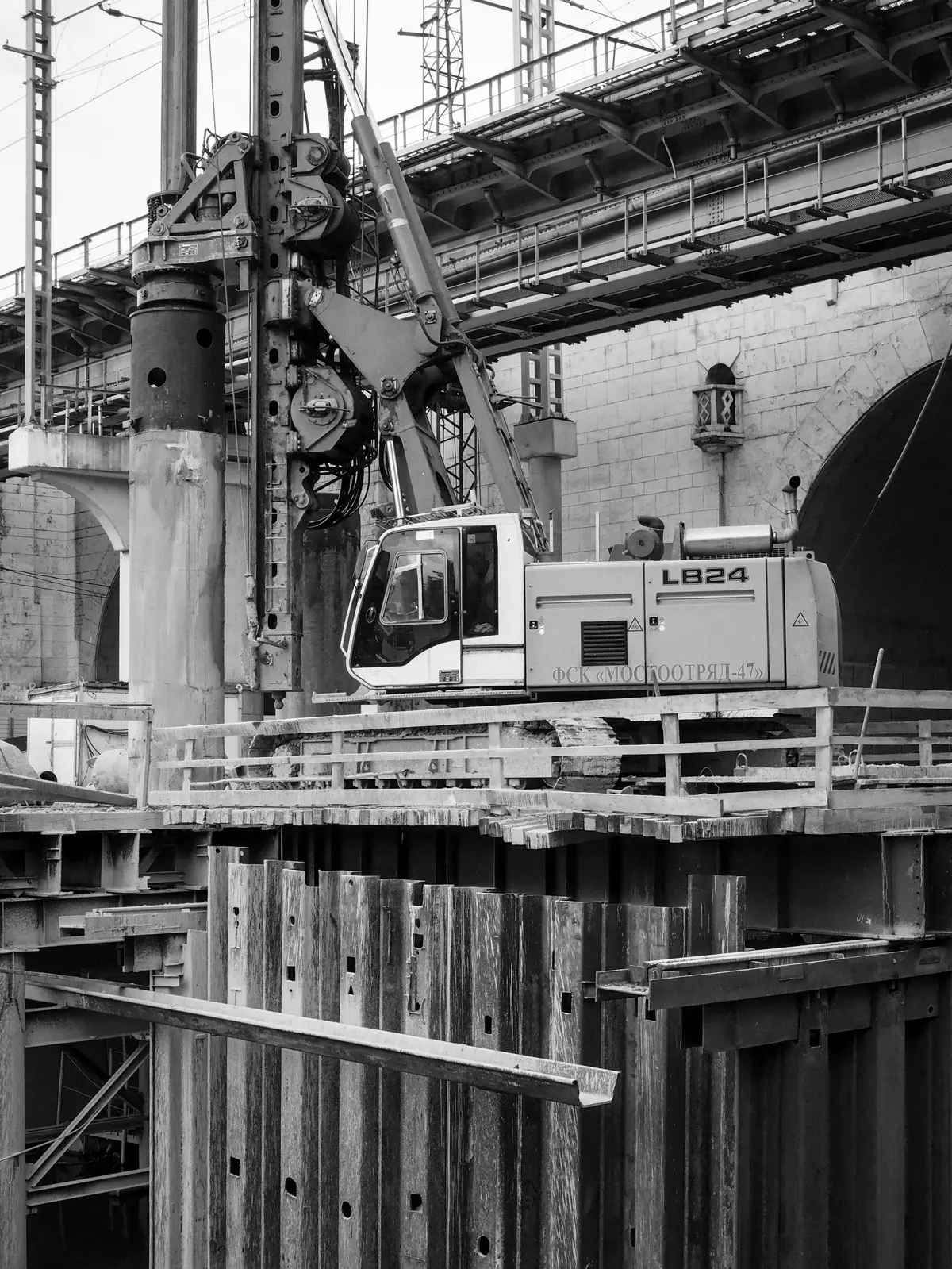
A helical pile is a driven deep foundation component that transfers structural loads to stable soil strata by bypassing weak surface layers. Rather than resting on shallow bearing plates, these elements function like industrial-grade screws that lock into competent ground.
Core Shaft Dimensions and Material Grades
The central shaft serves as the primary load-bearing column, and its structural integrity dictates the entire system's performance. Manufacturers typically specify high-yield carbon steel to withstand the extreme bending and shear forces encountered during both driving and long-term service.
Dimensional consistency is non-negotiable. Even minor variances in shaft diameter or wall thickness can compromise the coupling mechanisms between sections, creating weak points that fail under heavy utility or solar array loads. We consistently recommend hot-forged shaft construction over traditional casting processes. Hot-forging realigns the internal metal grain structure, which dramatically improves impact resistance and eliminates hidden porosity defects that could trigger sudden brittle fractures.
Surface preparation also plays a critical role in longevity. A uniform protective coating prevents galvanic corrosion at the soil-metal interface, ensuring the base steel maintains its designed yield strength throughout decades of exposure to aggressive groundwater and shifting pH levels.
Torque Application for Downward Load Transfer
Understanding how rotational force becomes vertical holding power requires looking at basic mechanics. Imagine driving a standard deck screw into dense timber: the harder you twist, the deeper it penetrates until the threads engage solid material. Helical piles operate on this exact principle.
During installation, a hydraulic drive head applies continuous rotational energy that forces the pile forward through the ground. This action displaces soil rather than excavating it, which immediately generates passive resistance around the shaft. The applied torque does not just move the pile; it mechanically compresses the surrounding earth, creating a tight interlock that translates rotational effort into massive vertical friction.
Once the drive sequence stops, the installed pile effectively becomes a rigid mechanical key embedded in stable ground. Engineers rely on this torque-to-friction conversion to anchor transmission towers, guy wires, and foundation posts without requiring extensive concrete footings or prolonged curing times.
Helix Plate Geometry for Soil Penetration
The helical plates are rarely simple flat discs welded randomly onto the shaft. Their spatial arrangement, pitch angle, and edge reinforcement are mathematically calculated to match specific soil profiles. Proper geometry ensures the pile advances smoothly without binding or inducing excessive lateral sway during installation.
Flight pitch refers to the distance between successive plates. Wider spacing allows rapid penetration through loose sands or soft clays, while tighter pitches increase soil displacement and improve grip in highly cohesive formations. If the pitch is mismatched to the ground conditions, operators often experience drill-down refusal or uneven load distribution.
When the pile reaches a target bearing layer, multiple flights work together to spread structural weight across a broader surface area. This load-distribution mechanism prevents point-loading failures and allows the foundation to safely support dynamic tension, compression, and lateral wind loads common in utility infrastructure projects.
| Component | Technical Specification | Quality & Testing | Engineering Function |
|---|---|---|---|
| Steel Shaft & Helical Plates | Hot-forged construction with precision-welded bearing flights | In-house load and gauge testing per IEC 120 standards | Transfers structural loads to deeper, stable soil strata |
| Corrosion Protection System | ISO 1461 compliant hot-dip galvanizing exceeding 85 microns mean thickness | SGS verified coating integrity and adhesion | Ensures long-term durability in high-moisture and aggressive soil environments |
| Installation Mechanics | Hydraulic torque-driven penetration optimized for variable soil profiles | Mandatory double-review QC process on 100% of products before packaging | Enables rapid foundation stabilization with minimal site excavation |
| Structural Brackets & Connectors | High-tensile steel mounting hardware engineered for axial and lateral load distribution | Rigorous dimensional tolerance checks maintaining strict ±1mm accuracy | Securely anchors superstructures such as solar arrays, power transmission towers, and civil infrastructure |
| Geotechnical Adaptability | Multi-flight plate design optimized for rocky, sandy, and soft clay formations | Mechanical performance verification for extreme environments and high-breaking load requirements | Provides reliable deep-foundation support across diverse global climate zones |
Design Codes and Capacity Standards
Torque-to-Capacity Calculation Methods
In the field of helical pile foundations, guessing is not an option. The industry standard method for determining the ultimate capacity of a pile relies on a direct correlation between the installation torque and the load-bearing potential. The fundamental equation used is Ultimate Capacity ($Q_u$) = Torque Correlation Factor ($K_t$) × Installation Torque ($T$). However, a common misconception is that peak torque alone defines capacity. In practice, engineers calculate the effective torque by averaging the readings taken over the final 3 feet of installation depth, measured in 1-foot increments.
This method filters out surface friction and ensures the capacity is derived from the competent soil stratum where the anchor actually holds. It is critical to understand that the $K_t$ factor is not universal; it varies based on the manufacturer's shaft geometry, helix configuration, and the specific soil conditions. Relying on a generic rule of thumb without referencing the specific manufacturer's technical manual can lead to severe under-designing or over-costing. We ensure that every project we support provides the specific $K_t$ curves for our shaft sizes to eliminate calculation ambiguity.
ISO and IEC Testing Compliance
For utility-grade hardware, compliance with international standards is non-negotiable for passing tenders and ensuring long-term reliability. Our manufacturing protocols strictly adhere to ISO 1461 for hot-dip galvanizing. This standard is critical because it governs the coating thickness that protects steel from corrosion. We consistently achieve a mean coating thickness exceeding 85 microns, providing a smooth, bright finish that offers superior protection against harsh environments compared to the minimum requirements of cheaper competitors.
Beyond corrosion protection, our products undergo rigorous testing per IEC 120 standards. This standard defines the test methods for hardware, specifically focusing on gauge and load testing. While many factories visually inspect products, we submit every batch to mechanical verification to ensure the dimensions and physical properties meet the strict tolerances required for high-voltage transmission. This compliance is not just paperwork; it is the result of our dedicated 10-person QC team monitoring every stage of production.
Load Rating Verification through Gauge Testing
A rated load is only as good as the verification process behind it. Gauge testing is the physical process of verifying that the hardware fits the corresponding conductor or pole dimensions perfectly. Even a minor deviation—sometimes as little as 1mm—can create stress concentrations that lead to premature failure under load. We utilize automated and semi-automated machinery to maintain dimensional accuracy, but human oversight remains the final filter.
We enforce a Double-Review Process where 100% of products are inspected twice before packaging. This means that before a box of pole bands or anchor bolts leaves our factory, it has passed a preliminary dimensional check and a final random or full audit. In our experience, this redundancy is the only effective way to catch the microscopic inconsistencies in threading or hole sizing that can cause massive installation delays for utility contractors.
Safety Factors in Utility Grade Installations
The "Safety Factor" (or Factor of Safety) is the buffer between the maximum expected load and the rated breaking strength of the hardware. For utility applications, where failure can result in catastrophic blackouts or infrastructure collapse, we design with significantly higher safety margins than standard commercial construction. However, the safety factor is not just about the math; it is about the material integrity.
This is why we prioritize hot-forging technology over traditional casting. Casting can create internal air pockets and weak structural grains, creating unpredictable failure points under dynamic loads (such as wind-induced vibration on power lines). Hot-forging aligns the grain structure of the steel, resulting in superior structural strength and impact resistance. By combining this manufacturing method with SGS verified processes, we deliver hardware that doesn't just meet the theoretical safety factor on paper but holds up under the chaotic physical stresses of real-world utility grids.

Site Preparation and Layout Marking
Proper site preparation and accurate layout marking are the foundational steps that determine whether a helical pile foundation project proceeds efficiently or suffers costly delays. When contractors skip rigorous pre-installation surveys, they frequently encounter misaligned piles, equipment collisions with underground utilities, or uneven load distribution across solar arrays and utility structures. The immediate solution requires clearing all surface debris, establishing a verified coordinate grid, and marking exact pile engagement points before any heavy machinery enters the zone.
Site Clearance and Access Corridors
Before any piling equipment can operate effectively, the installation zone must be stripped of topsoil debris, vegetation, and existing concrete pads that could deflect the rotating helix plates. Utility-grade projects typically require a minimum clearance corridor of three meters (ten feet) on all sides of each pile location. This space allows compact track loaders or mini-excavators to approach the marked points at the correct angle without striking adjacent ground features. Removing loose organic material also prevents soil compaction issues that could create inaccurate baseline resistance measurements during actual drive-in procedures.
Establishing Precise Grid Coordinates
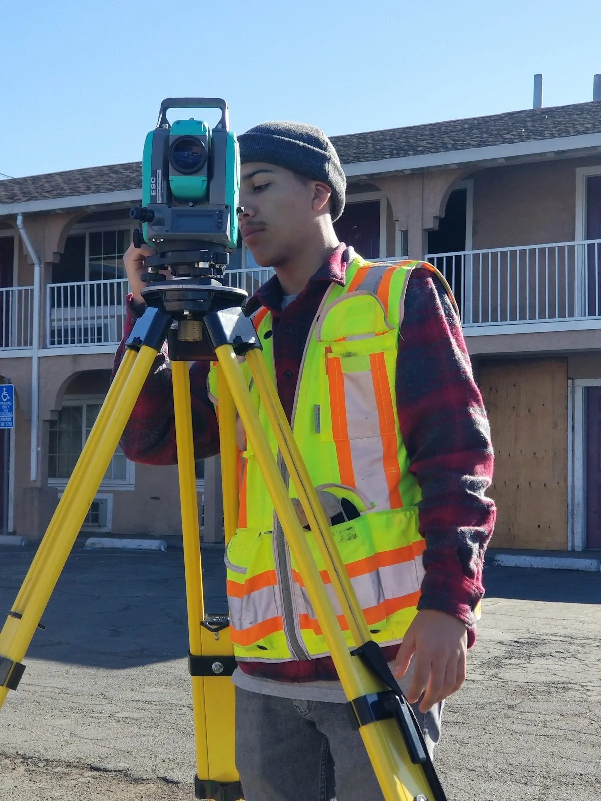
Layout marking transforms architectural blueprints into physical ground references. Survey teams utilize Real-Time Kinematic GPS (RTK-GPS) or robotic total stations to map structural load points directly onto the terrain. For utility pole lines and commercial solar racking, stakes are driven precisely at calculated intervals to align with guy wire tension vectors or panel frame supports. Each marked point must correspond to a verified elevation datum to guarantee that cross-arm braces and mounting hardware sit perfectly level once installed.
- Precision Tolerance: Standard industry practice requires placement accuracy within ±25mm (±1 inch) of the design coordinate to prevent stress fractures in steel arms and fasteners.
- Weight Distribution Mapping: Markings must account for the concentrated downward load of the deck or pole structure, ensuring pile spacing matches the engineered shear load calculations.
- Surface Obstruction Removal: All rocks, brush, and uneven soil mounds must be cleared within a one-meter radius of each stake to allow unhindered helix penetration.
Initial Helix Alignment and Engagement
Correct vertical positioning and controlled low-speed rotation during first contact prevent shaft binding, ensure optimal soil displacement, and guarantee immediate load transfer efficiency.
Why Initial Alignment Dictates Installation Success
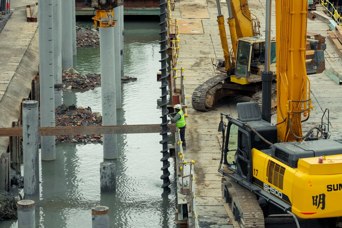
When installing helical anchors or piles, the initial few inches of penetration dictate the entire project's timeline and structural integrity. The primary pain point buyers face is misalignment during entry. Even a slight angular deviation at the surface causes the leading helix plate to bind against undisturbed soil, instantly spiking operational torque. This often results in bent shafts, stalled drives, or compromised load capacity. Think of it like driving a lag bolt into dense timber: if the head is not perfectly square and the turning speed is too high, the threads strip immediately. Proper technique requires patience and mechanical precision.
To avoid these costly errors, the installation crew must position the assembly strictly vertical before engaging the drive motor. The machine selected should match the required downward axial force, as soft topsoil offers little resistance initially, but the transition into denser strata demands consistent downward pressure to keep the helix biting forward rather than spinning in place.
Optimizing Low-Speed Rotation and Plate Geometry
Engagement begins with low-speed rotation, typically operating between 15 and 30 RPM, allowing the helix plate to cut into the soil profile smoothly. At this stage, torque is not yet measuring ultimate bearing capacity; instead, it is actively transferring downward force along the core shaft. As the leading edge engages, the soil is displaced radially rather than compressed, reducing friction and preventing premature refusal. This method ensures the helix plate geometry functions exactly as engineered, slicing through root mats, gravel, or clay without deflecting.
- Vertical Alignment Threshold: Deviations exceeding 1 to 2 degrees at entry will amplify exponentially with depth, creating lateral stress concentrations that exceed standard yield limits.
- Helix Plate Flatness: Manufacturing tolerances must remain within a strict 1mm deviation to ensure uniform soil penetration and prevent uneven torque spikes during the initial bite.
- Shaft Rigidity: Hot-forged construction provides superior grain structure continuity compared to traditional casting, delivering the necessary torsional strength to resist bending moments during aggressive initial engagement.
Never increase drive RPM to "power through" resistant topsoil layers. Excessive rotational speed generates centrifugal forces that cause the helix to ride over compacted soil instead of penetrating it, leading to installation delays and potential equipment damage.
Tracking Torque for Load Verification
Tracking installation torque via calibrated hydraulic gauges provides immediate verification of pile capacity. Operators must distinguish between superficial friction and actual bearing resistance to prevent dangerous capacity overestimation.
Distinguishing Friction Torque from Bearing Resistance
Installation torque does not measure static capacity directly; it measures the mechanical resistance encountered during rotation. Upper soil layers frequently generate high friction torque as the shaft and shallow helices push through loose or cohesive material. This initial resistance often masks the true structural engagement happening deeper underground.
Engineers treat friction torque as temporary operational drag rather than structural proof. The genuine load-bearing moment occurs when the lowest helix plates penetrate a competent stratum. Only this bearing torque reliably correlates with the intended vertical capacity. A simple analogy compares it to fastening a screw into plywood: the initial turns meet surface friction, but the final tightness confirms the anchor has locked into solid material.
- Friction Zone Indicators: Steady, moderate resistance values recorded during the first few rotations indicate shaft engagement with topsoil or loose fill.
- Bearing Zone Confirmation: A sharp, sustained increase in gauge PSI signals the primary helices have reached dense clay, sand, or bedrock.
- Resistance Drops: Sudden decreases in torque usually indicate voids, soft pockets, or failed soil contact, requiring immediate operational pauses.
Calibrated Gauge Monitoring Protocols
Real-time verification requires standardized hydraulic resistance measurement systems installed on the driving equipment. Field crews attach precision load cells or pressure transducers directly to the hydraulic motor circuit. These devices convert fluid pressure into readable torque metrics expressed in foot-tons or kilonewton-meters.
Continuous monitoring allows contractors to adjust installation speed and hydraulic flow instantly. If the pressure gauge reads consistently below the design threshold near the target depth, the pile has not achieved the required penetration. Conversely, exceeding maximum allowable torque triggers automatic shutdowns to prevent shaft twisting or helix deformation.
📋 Standard Monitoring Sequence
- Zero Calibration: Verify gauge baselines before deployment to eliminate pressure drift errors.
- Depth Logging: Record cumulative torque readings at every five-foot interval to map subsurface density shifts.
- Threshold Verification: Compare final gauge readings against project-specific capacity charts before halting operations.
Correcting Torque-to-Capacity Misinterpretations
A common field error assumes that higher installation torque automatically equals a wider safety margin. This assumption ignores critical variables like soil density stratification, pile geometry, and friction coefficient variations. A pile driven through abrasive gravel may register extreme torque without actually seating into the designated load-bearing layer.
Proper load verification relies on empirical correlations rather than raw machine resistance numbers. Design engineers calculate expected torque using established multipliers that account for helix diameter and pitch angle. Contractors cross-reference these calculated benchmarks with live gauge data to validate penetration depth.
Never rely solely on torque readings for high-liability infrastructure projects. Empirical correlation serves as a rapid field check, but critical utility structures still require formal geotechnical investigations and static load testing to verify ultimate capacity.
Mechanical resistance gauges provide an essential quality assurance layer during installation. By isolating true bearing torque from superficial friction, teams can confirm that each element penetrates the target stratum before termination. This disciplined verification process prevents premature cutoffs and eliminates costly over-drilling scenarios.
Maintain consistent hydraulic flow rates during the final penetration phase. Variable pump speeds create artificial torque spikes that distort gauge readings and compromise the accuracy of your capacity verification.
Identifying Subsurface Resistance Shifts
Navigating subsurface obstructions during helical anchor installation requires recognizing sudden torque spikes and deploying mechanical relief tools before forcing the drive head. When an installation encounters unexpected boulders, compacted till, or buried debris, continuing to apply downward axial force typically results in helix plate deformation or shaft twisting. The correct engineering response is to stop rotation, assess the obstruction depth, and attach a pre-auger or utilize a specialized cutting-tip helix to fracture and clear the obstacle while preserving the structural integrity of the central shaft.
Soil density variations directly influence installation dynamics. As the helical bearing blades advance, the hydraulic drive system registers continuous torque values. A sudden deviation from the predicted soil profile indicates contact with a hard stratum or obstruction. Operators must distinguish between normal soil engagement and rigid barriers. Forcing penetration through unyielding material transfers excessive stress to the weld joints between the shaft and helix plates. This stress concentration frequently leads to catastrophic failure under operational load. Recognizing the exact depth of the obstruction allows for targeted intervention rather than blind mechanical force.
Mechanical Relief Strategies for Hard Strata
Overcoming dense geological barriers requires auxiliary drilling components that match the helical geometry. Two primary mechanical solutions exist for clearing obstructions without damaging the anchor assembly. Each method serves a specific ground condition profile.
- Pre-Auger Attachments: Screw-mounted drill flights positioned ahead of the bearing helix. These cut through rocky soil and loose debris, reducing the rotational resistance felt by the main anchor body.
- Cutting-Tip Helices: Helical plates featuring reinforced beveled edges or integrated carbide wear points. These designs fracture compacted clay, soft rock, and gravel layers upon initial contact, allowing continuous advancement.
- Material Selection: Utility-grade installations require hot-forged steel construction for relief tools, ensuring the components withstand impact forces that would fracture cast alternatives.
Selecting the appropriate mechanical aid depends on the anticipated ground composition. Dimensional consistency remains critical; a pre-auger must align within a 1mm tolerance relative to the central shaft to prevent eccentric loading during extraction or final seating. Misalignment creates uneven stress distribution, which accelerates fatigue in high-tension guy wire or solar array support applications.
Maintaining Structural Integrity Under Load
Once the obstruction is cleared or bypassed, the installation proceeds to full bearing depth. Continuous torque monitoring remains essential throughout this phase. The relationship between applied torque and ultimate capacity does not change, but the load transfer mechanism adapts to the newly formed soil interface. Shaft friction develops along the embedded length as the surrounding medium grips the galvanized surface. In cohesive soils, this skin friction provides supplementary capacity alongside the primary helix bearing points.
Engineers must verify that the drive head maintains sufficient downward axial force to seat the anchor securely after clearing the barrier. If the machine lacks adequate break-out force, the helical plate may spin in place without advancing, rendering the installation non-compliant with standard gauge testing protocols. Proper load verification requires correlating real-time torque readings with documented soil logs. Consistent torque increases indicate successful helix engagement, whereas erratic fluctuations signal recurring subsurface voids or fragmented bedrock requiring repeated pre-augering cycles.
Final Depth Verification and Capping
Final depth verification and capping confirm that a helical pile has reached its target elevation within strict tolerance limits and securely attaches the structural bracket for load transfer. Achieving this requires precise elevation surveys, controlled final penetration, and proper capping geometry to prevent soil displacement or bracket slippage under operational tension.
Utility developers and solar project managers frequently encounter costly schedule delays when piles are either over-driven past their designed bearing stratum or left short of the required grade. The core engineering challenge lies in verifying exact depth while maintaining vertical alignment, then transferring structural loads safely through a properly installed termination cap. Skipping rigorous elevation checks or using underspecified capping hardware inevitably leads to bracket fatigue, misaligned cross-arms, or compromised guy-wire tension in pole line systems.
Elevation Verification and Tolerance Management
Final depth verification is not simply a matter of watching the drill reach a certain marker; it is a measured confirmation that the pile tip intersects the engineered load-bearing soil layer or rock stratum. Installers utilize total station surveys or laser leveling to record the exact cut-off elevation before any capping occurs. Industry standards typically mandate a vertical tolerance of ±10 mm and a lateral deviation not exceeding 0.5% of the embedded depth to ensure predictable load distribution.
- Torque-to-Elevation Correlation: As the pile approaches its target depth, the installer monitors the final few rotations to confirm that soil resistance aligns with design expectations. A sudden drop in resistance often signals loose fill or a void, requiring immediate depth recalculation.
- Section Splice Verification: When multiple steel shaft sections are bolted together to reach total depth, each connection must be torque-checked and visually inspected for flush alignment. Gaps between flanges create stress concentrations that can shear under cyclic wind loading.
- Cut-Off Planning: The pile shaft must be trimmed at the precise elevation that allows the structural bracket to sit perfectly level. Over-trimming removes necessary embedment; under-trimming leaves excess shaft that interferes with base plate seating.
Structural Capping and Bracket Attachment
Once the final elevation is locked, the termination phase begins. The capping plate serves as the mechanical interface between the buried helical system and the above-ground pole line or solar mounting frame. It must distribute point loads across the helix bearings without inducing bending moments in the shaft. Standard practice utilizes minimum 10 mm thick mild steel or galvanized structural plates, secured with Grade 8.8 or higher structural fasteners to prevent loosening from vibration.
The physical analogy is straightforward: think of the capping assembly as a foundation cornerstone. If it sits unevenly or is fastened loosely, the entire structure above it will wobble under dynamic loads like wind or seismic activity. Proper installation requires shimming the plate to achieve perfect horizontal alignment, followed by incremental tightening of anchor bolts in a crisscross pattern to seat the plate evenly against the soil surface.
For B2B procurement and site supervision, the final deliverable is a verified as-built elevation record paired with a torque log for all capping fasteners. This documentation bridges the gap between field installation and utility commissioning, ensuring that the structural connection meets both design specifications and long-term reliability standards. When executed correctly, the capped helical foundation provides a rigid, corrosion-resistant termination point that withstands decades of environmental cycling without maintenance intervention.
Primary Applications and Use Cases
Selecting the correct helical pile configuration is not a generic process; it requires a precise match between specific soil mechanics and the structural load demands of the application.
Matching Soil Density to Installation Depth
Determining the correct installation depth is strictly a function of soil density and the location of competent load-bearing strata. In loose or sandy soils, the helix must penetrate significantly deeper to reach a layer dense enough to generate the required friction and end-bearing pressure. Conversely, in dense clay or hardpan, the required depth is shallower, but the installation torque will be substantially higher. We have found that using hot-forged steel shafts is critical here; unlike lower-grade cast materials, our forged components maintain structural integrity under the extreme torsional stress required to penetrate dense layers without twisting or shearing. Installers must monitor torque readings closely to ensure the pile has engaged with soil capable of supporting the design load.
Structural Load Requirements for Solar Arrays
Solar energy projects present a unique challenge because the structures are relatively lightweight but possess massive surface areas, making them highly susceptible to wind uplift. The primary structural requirement for solar arrays is often tension resistance rather than just compression. The helical pile acts as an anchor, preventing the racking system from being pulled out of the ground during high-wind events. Because solar farms often cover acres of land, consistency in manufacturing is vital to ensure uniform load capacity across thousands of points. Our automated production lines deliver this uniformity, ensuring that every pile meets the strict dimensional tolerances necessary for rapid, large-scale solar deployment.
Guy Wire Tension Specifications for Pole Lines
In utility and transmission projects, guy anchors are subjected to continuous, high-tension loads that keep utility poles vertical and stable. The application demands anchors that do not creep or shift over time, as even minor movement can compromise the alignment of power lines. In our experience supplying grids in extreme environments like Russia, we have learned that standard anchors often fail under cyclic freezing and thawing. Therefore, we specify anchors with enhanced shaft geometries and specialized galvanizing that exceeds standard thickness to resist corrosion. The engineering focus here is on the immediate transfer of tensile force from the guy wire to the soil, ensuring the anchor does not pull out under maximum line tension.
Project Type Selection Based on Ground Conditions
Choosing the right helical pile system is entirely dependent on a thorough geotechnical analysis of the site. For rocky terrain or ground with large boulders, standard round-shaft piles may deflect or bounce off obstructions; in these cases, a rugged square-shaft configuration or specialized rock piercing lead is necessary. In marine environments or areas with high water tables, the priority shifts to corrosion resistance, requiring thicker galvanization or specialized alloys. We frequently work with clients to customize the helix configuration—such as adjusting the plate diameter or pitch—to suit specific ground conditions where off-the-shelf solutions would fail. Proper selection prevents installation delays and ensures the foundation performs reliably over its intended lifespan.
| Application Sector | Structural Function | Technical Specification | Installation Characteristic | Engineering Advantage |
|---|---|---|---|---|
| Solar & Renewable Energy | Compression & Uplift Resistance | Hot-forged shaft construction; ISO 1461 galvanization exceeding 85 microns; automated dimensional control | Immediate load-bearing capacity with zero curing time | Enables rapid deployment in remote locations while minimizing ecological footprint |
| Residential & Commercial Underpinning | Vertical Gravity & Lateral Stabilization | Semi-automated precision machining; ±1mm tolerance compliance; IEC 120 gauge verification | Hydraulic torque-driven installation directly correlated to soil bearing capacity | Restores distressed foundations without heavy excavation or structural vibration |
| Marine & Coastal Infrastructure | Tension Anchoring & Scour Protection | High-tensile forged steel core; ISO 1461 enhanced corrosion protection; SGS certified load testing | Operable year-round in sub-zero temperatures and high water table conditions | Prevents waterfront foundation undermining during extreme weather and tidal fluctuations |
| Power Transmission & Utility Grids | Dynamic Wind Load & Equipment Weight Support | Customizable helix plate geometry; hot-forged structural reinforcement; 100% double-review QC protocol | Modular assembly allows quick adaptation to varying pole line hardware requirements | Ensures grid reliability in extreme environments such as high-latitude arctic regions |
| Modular & Temporary Construction | Reversible Compression & Tensile Forces | Recyclable hot-forged alloy; standardized modular coupling; automated manufacturing tolerances | Easily extracted and reused across multiple project lifecycles | Eliminates permanent ground alteration while supporting agile, cost-effective scaling |
Conclusion
Successful installation demands reading the soil, not just turning steel. You need precise torque monitoring to verify capacity against ISO design codes, or your solar arrays face serious risks. Cast helixes often crack under high load, but hot-forged shafts withstand the stress. We prioritize manufacturing precision because a failed foundation costs far more than the pile itself. Trust the torque reading. Match your steel grade to the specific soil conditions. That is how you secure a structure for decades.
We understand the technical risks involved in these projects. Our engineers are ready to review your early-stage designs and load requirements before you place an order. We can help you verify soil density matching and torque calculations to ensure full compliance. Use our team as a technical backup. There is no obligation to purchase, just straight answers on installation specifications and safety factors.
Frequently Asked Questions
What is the difference between helical piles and anchors?
While similar in design, helical piles are primarily engineered to support significant vertical compression loads for structures. Anchors are optimized to resist tension loads, commonly used to secure utilities or tents against uplift. The distinction lies in their engineering application and the primary direction of the load.
Do helical piles require geotechnical soil testing?
Yes, geotechnical soil testing is critical for determining the correct helix configuration and shaft size. Testing provides necessary data on soil stratigraphy and bearing capacity to ensure the foundation meets load requirements. Installing piles without this analysis risks structural failure or inadequate performance.
Can helical piles resist high lateral loads?
Helical piles possess limited capacity to resist lateral, or sideways, forces compared to their axial strength. Their performance against lateral loads depends heavily on the stiffness of the surrounding soil and the depth of the top helix. For high lateral forces, additional structural bracing or specific design modifications are often required.
Is standard galvanizing enough for aggressive soil?
Standard galvanized coatings may not be sufficient for soils with high corrosivity, low pH, or high electrical resistivity. In these aggressive environments, engineers often specify additional protective measures such as sacrificial anodes or specialized coatings. Selecting the proper corrosion protection is vital for ensuring the foundation's service life.
What equipment installs helical piles efficiently?
Efficient installation typically requires hydraulic machinery equipped with high-torque drive motors mounted on excavators or skid steers. Dedicated drive heads are essential to ensure proper torque application and alignment during the screwing process. The selection of specific equipment depends largely on site accessibility and the required installation depth.