
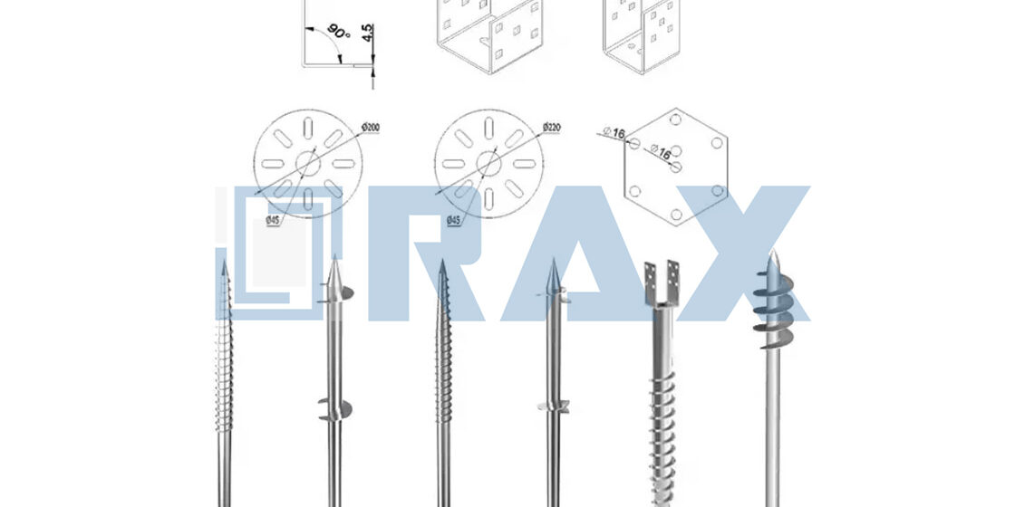
A single batch of substandard hardware will delay a major grid expansion by months and shatter your supplier defect rate KPIs. Foundation failures rarely stem from bad concrete. They happen when projects use mismatched tower foundation anchors for the extreme soil conditions along the route. We enforce a strict ISO 1461 hot-dip galvanizing standard with a mean zinc thickness exceeding 85 microns at Rax Power, because anything thinner rusts through within a decade in wet, corrosive ground.
This analysis bypasses theoretical design fluff and compares the actual installation constraints of helical anchors versus grouted rock systems. We evaluate torque requirements, uplift resistance, and drill-rig timelines across different soil classes. The hardware data matters. You will walk away with a strict selection criteria that aligns your overhead line configuration with the correct underground hardware to guarantee your next grid rollout hits its on-time delivery targets without a single batch failure.
Evaluating Foundation Failure Risks and Soil Constraints
Foundation failure in remote transmission lines is rarely due to the anchor hardware itself, but rather the fatal mismatch between the selected foundation solution and the unverified soil variability at the specific tower location.
Mapping Soil Class Variability Across Remote Routes
Relying on generalized regional soil data is a primary catalyst for foundation failure in remote transmission projects. Geotechnical reports must provide borehole data at specific tower coordinates rather than interpolating from distant samples, as soil composition can shift drastically within meters of terrain. Transition zones between soft clay and dense rock are particularly hazardous; without identifying these boundaries, the installed foundation may face unexpected settlement or insufficient pull-out resistance.
Calculating Ultimate Compression and Uplift Capacities
Accurate load capacity analysis requires distinguishing between the ultimate bearing capacity and the allowable working load, applying a minimum safety factor of 2.0 to 2.5 depending on the voltage classification. While compression loads are managed by the broad base area of concrete pads or anchor helices, uplift resistance is the critical failure mode for guy wires and tower legs. It is imperative to calculate the uplift capacity based on the failure mechanism of the soil—whether it is shallow shear in cohesive clays or deep vertical shaft friction in granular sands.
Mitigating UHV Tower Design Deficiencies
Ultra-high voltage (UHV) structures impose extreme static and dynamic loads that magnify minor design flaws. Traditional foundation designs often underestimate the cyclic loading caused by wind-induced vibration on taller towers, leading to fatigue failure in anchor rods. Mitigation involves selecting anchors with high ductility and fatigue resistance, such as hot-forged triple-eye rods, which outperform brittle cast alternatives under high-impact stress.
In our experience supplying markets like Russia and South America, we have found that hot-forged components provide superior structural integrity for these high-load scenarios. Our manufacturing ensures a strict 1mm tolerance, eliminating the play and stress concentration points that cause premature failure in UHV applications. By utilizing steel with a mean zinc coating thickness exceeding 85 microns (ISO 1461), we ensure these critical connection points resist the corrosive soil stressors that often trigger structural collapse.

How do anchor requirements differ across tower structures?
Anchor selection is dictated strictly by the tower’s load path: mitigating bending moments in monopoles, resisting massive uplift in lattice structures, or absorbing sustained guy-wire tension.
Transmission structures process mechanical loads fundamentally differently. Self-supporting lattice towers generate extreme vertical and uplift forces, particularly under asymmetric conductor loading or dead-end conditions. These structures rely on rigid foundation footings where the anchor must mobilize a massive volume of soil to counter extraction. In contrast, guyed structures offload lateral wind and weight forces into high-tension guy cables, transferring the load diagonally into the earth. The foundation anchor here acts purely in deep tension, requiring exceptional pull-out resistance rather than compression tolerance.
Monopole and H-Frame configurations present an entirely different engineering challenge. They function as cantilever beams embedded in the earth, generating significant overturning moments and lateral shear forces at the groundline. Anchoring systems for these structures must resist continuous dynamic flexing rather than static linear loads. We design our helical and expanding anchor shafts specifically to maintain structural rigidity under these sustained multi-directional stresses, preventing foundation drift over the tower’s lifecycle.
Aligning Foundation Anchors with Transmission Line Configurations
Selecting the correct anchor means matching the deployment strategy to the overhead line’s structural profile. Heavy EHV/UHV dead-end towers, which experience maximum breaking loads during conductor stringing or failure events, demand heavy-duty expanding or cross-plate anchors engineered for ultra-high lateral capacity. Conversely, long-span guyed suspension towers benefit from driven helical anchors, which can be installed rapidly in remote, mixed-soil corridors without concrete curing delays.
| Tower Structure | Primary Anchor Type | Soil Suitability | Load Demand | Rax Power Engineering Edge |
|---|---|---|---|---|
| Heavy Lattice Transmission Tower (EHV/UHV) | Cross-Plate & Expanding Anchors | Medium-to-hard soil and dense clay | Ultra-high vertical and uplift load | Hot-forged cross-plate anchors with ISO 1461 galvanizing (>85 microns) for permanent corrosion resistance |
| Guyed Suspension Tower | Helical Anchors (Round/Square Shaft) | Soft, mixed, and wet soils | High sustained guy-wire tension | Precision-forged helical shafts ensure seamless drive-tool fit, eliminating on-site modification |
| Dead-End / Angle Tower | Expanding & No-Wrench Screw Anchors | Variable and rocky backfill terrain | Maximum lateral and breaking load | Specialized high-breaking-load design proven in extreme-environment projects |
| Monopole Tower | Helical (Square Shaft) & Rock Anchors | Rocky, compacted, and urban right-of-way | High moment-resisting capacity | Automated production guarantees strict 1mm tolerance for consistent foundation alignment |
| H-Frame Distribution Pole | Expanding & Guy Grip Anchors | Standard utility soil corridors | Medium-to-high guy anchor pull-out | Full IEC 120 load-tested anchors with double-review QC for tender compliance |
| Solar / Micro-Grid Mounting Structure | Helical Anchors (Round Shaft) | Sandy, loamy, and reclaimed ground | Moderate uplift and shear load | OEM/ODM custom mold development adapts anchor geometry to project-specific soil reports |
| Coastal / Corrosive-Zone Tower | Galvanized Cross-Plate & Helical Anchors | Saline, marshy, and high-moisture soil | Sustained load with 30+ year life cycle | ISO 1461 hot-dip coating (>85 microns mean thickness) verified by SGS for permanent installation durability |
Helical Foundation Anchors for Variable Soil Classes
Deploying helical foundation anchors in variable soil classes demands precise calculation of shaft geometry to counteract differing shear strengths and prevent premature torque refusal during inter-strata transitions.
Transmission routes routinely cross vastly different geological profiles, transitioning from soft clay to dense sand within a single span. Helical anchors provide a distinct advantage here because their holding capacity is derived from the bearing capacity of individual helix plates, rather than relying solely on skin friction along the shaft. However, the primary engineering challenge is managing the shear stress placed on the shaft when penetrating harder intermediate strata to reach a stable load-bearing soil class.
Shaft Tolerance and Forging Integrity Under High Torque
To achieve the necessary depth in dense or mixed strata, installation rigs apply immense torque, creating severe torsional stress on the anchor shaft. Any dimensional inaccuracy in the shaft or coupling interfaces introduces critical failure points. In our manufacturing facility, we utilize automated production to maintain strict 1mm tolerances on both round and square helical shafts. We rely on hot-forging for the shaft eyes and connection hubs to ensure superior structural density, guaranteeing that the drive tool mates flawlessly with the shaft without requiring destructive field modifications.
Helix Pitch and Soil Class Compatibility
The geometry of the helix plates must strictly adhere to true helix pitch standards—typically a 3-inch pitch—to ensure continuous soil engagement without augering or disturbing the bearing stratum during installation. In cohesive, soft soil classes, multi-helix configurations are required to distribute uplift loads effectively. For utility poles in regions with freezing or highly compacted soils, such as the extreme environments we supply in the Russian market, the shaft diameter and helix edge profiles must be explicitly engineered to withstand high breaking loads without shearing.
Expanding Foundation Anchors for Dense Soil Strata
In dense soil strata, successful anchorage depends on mechanical interlock rather than skin friction; expanding anchors must reliably deploy their heads against high subsurface resistance to achieve rated pullout capacity.
Dense soil strata, such as hardpan or stiff clay, present unique challenges for foundation anchoring. Unlike loose soils where helical plates gain holding capacity through the surface area of the screw threads, dense soils require an anchor that can penetrate the resistance layer and then create a physical obstruction or ‘bulb’ to lock the structure in place. If the expansion mechanism fails to trigger or deploy fully due to the high density of the surrounding earth, the anchor essentially becomes a friction pile with significantly reduced load-bearing capabilities, leading to potential structural instability.
Mechanical Deployment in High-Density Subgrades
Expanding foundation anchors, specifically no-wrench screw anchors and toggle-type heads, are engineered for these exact conditions. The installation process drives the anchor rod to the required depth using the impact of a hammer or hydraulic driver. Once the target depth is reached in the dense strata, continued driving force acts against a stop mechanism, causing the anchor head to rotate or expand outward. This mechanical action transforms a linear driving force into a perpendicular locking force, anchoring the utility pole securely against the compacted soil.
The integrity of this expansion mechanism is paramount. In our foundry, we have moved away from traditional casting methods for these critical components in favor of hot-forging. We observed that cast heads can shatter under the high-impact shock required to penetrate dense earth. By utilizing hot-forging, we align the grain structure of the steel, providing superior impact resistance and ensuring the expansion mechanism deploys smoothly every time without fracturing.
Precision Manufacturing and Corrosion Defense
Precision is non-negotiable for expanding anchors. If the eye rod or the expansion sleeve is even slightly out of tolerance, the mechanism may jam or pre-maturely lock during installation. We utilize automated production lines to maintain a strict 1mm tolerance on all dimensions. This ensures that every drive tool fits seamlessly and that the internal expansion mechanism functions exactly as designed, eliminating the need for on-site modifications by the installation crew.
Beyond mechanical strength, the longevity of the anchor in dense soil is dictated by its resistance to corrosion, which can be exacerbated by the moisture retention characteristics of clay-heavy strata. We apply a hot-dip galvanizing process strictly compliant with ISO 1461, guaranteeing a mean coating thickness that exceeds 85 microns. This heavy-duty zinc layer provides a sacrificial barrier that protects the underlying steel, ensuring the anchor maintains its structural integrity for decades even in aggressive soil environments.
Cross-Plate Foundation Anchors for Uplift Resistance
Cross-plate foundation anchors resist uplift forces by mobilizing passive earth pressure against a buried bearing plate within a pre-drilled borehole. Ultimate uplift capacity depends on the intersection of plate geometry, rod tensile strength, and backfill compaction density—not soil classification alone.
Load Transfer Mechanics in Cross-Plate Anchor Systems
Cross-plate anchors operate as buried deadman systems. After the borehole reaches design depth, the cross-plate assembly is lowered and positioned so the plates bear horizontally against undisturbed soil. Backfill is then compacted in controlled lifts to restore shear strength. Under uplift loading, tension transfers through the anchor rod to the cross plates, which engage a truncated soil cone above them—the cone volume and plate bearing area together define ultimate capacity.
The governing failure mode in properly designed cross-plate anchors is rod yield, not plate bending. If the rod cross-section undersizes the design tension, elongation and eventual thread fracture occur before the soil cone fully mobilizes. Procurement specifications must match rod diameter to calculated breaking load rather than defaulting to a generic plate size from a catalog entry.
We hot-forge the cross-plate eyes and threaded rod ends from a single billet instead of welding coupler joints to plate assemblies. This removes the weld heat-affected zone—the primary failure initiation point in fabricated anchors subjected to cyclic wind loads on guyed transmission structures. Our 10-person QC team verifies thread engagement depth and plate-to-rod perpendicularity against IEC 120 gauge tolerances on every production unit before the galvanizing bath.
Breaking Load Requirements for Extreme-Environment Grids
Cross-plate anchors specified for Russian utility infrastructure routinely demand breaking loads that exceed standard thresholds because permafrost and seasonal thaw cycles reduce the effective soil cone volume above the bearing plate. Engineers compensate with larger plate diameters in the 150mm to 300mm range paired with higher rod tensile grades. The anchor must sustain rated uplift capacity through repeated freeze-thaw events without permanent plate deflection or dimensional drift in the bearing geometry.

Grouted Rock Foundation Anchors for Solid Terrains
When transmission routes intersect solid bedrock, grouted rock anchors provide the required uplift capacity by transferring structural loads directly to the rock mass through a cementitious grout bond, bypassing the need for mechanical soil displacement.
In solid terrains where helical or expanding anchors fail to penetrate, grouted rock foundation anchors become mandatory. The primary engineering challenge in these environments is ensuring adequate bond strength between the anchor shank, the grout, and the competent rock strata. Engineers must rely on precise geotechnical reports to determine rock quality designation (RQD) and uniaxial compressive strength. Designing the drill hole diameter and depth accurately is critical; an undersized hole limits load capacity, while an oversized cavity wastes expensive non-shrink grout and delays project timelines.
We manufacture our rock anchor rods using high-strength hot-forged steel rather than traditional casting, guaranteeing superior structural integrity under extreme tensile loads. By maintaining a strict 1mm tolerance in our automated production lines, we ensure that every threaded component and drive tool aligns perfectly, eliminating costly on-site modifications during the grouting and torqueing phases.
Corrosion Protection and Material Standards
The long-term viability of a grouted rock anchor heavily depends on its metallurgical properties and anti-corrosion treatment. Because these components are permanently encased in rock and grout, any premature degradation threatens the entire transmission tower’s stability. To combat this, our grouted anchor rods undergo hot-dip galvanizing compliant with ISO 1461 standards. This process guarantees a mean zinc coating thickness exceeding 85 microns. Additionally, 100% of these critical components undergo double-review load and gauge testing compliant with IEC 120 and SGS verification protocols before packaging.
Installation Methodologies and Equipment Specifications
Anchor performance is strictly installation-dependent. The applied torque, drill rig specifications, and installation methodology dictate whether a foundation achieves its engineered ultimate holding capacity or fails under lateral load.
Torque Requirements: Helical vs. Driven Expanding Anchors
Power-installed helical anchors rely on hydraulic rotary torque to advance the helix into the soil. The mechanical energy required to turn the anchor translates directly to its load-bearing capability, generally following a recognized 10:1 torque-to-holding-capacity ratio. Depending on soil density, hydraulic drive heads must deliver between 1,000 to 7,000 ft-lbs of continuous torque.
We engineer our helical anchor shafts and drive tools using automated machinery to guarantee strict 1mm tolerances. This precision fit is critical; any dimensional slack between the drive Kelly bar and the anchor socket will cause the corners to round off under extreme torque loads, halting the installation.
Conversely, driven expanding anchors operate on impact energy rather than rotational torque. These units are driven into the earth using a pile hammer striking a heavy internal steel rod. The holding capacity is generated only after reaching the target depth, when the anchor is mechanically pulled back to force the expanding blades outward into undisturbed soil. The critical specification here is the hammer’s impact rating, not rotational force.
Drill Rig Requirements and Timelines for Grouted Rock Anchors
Grouted rock anchor installation shifts the operational focus from driving to precision drilling. Contractors must deploy specialized hydraulic rotary-percussion drill rigs capable of boring through solid bedrock. This procedure requires substantial air compressor capacity to continuously flush rock cuttings from the deep borehole.
The defining constraint for grouted anchor projects is the timeline. Unlike mechanically driven or helical anchors that can be tensioned immediately upon installation, grouted systems require a specialized curing phase. Once the high-strength threaded steel is set, the grout mixture requires 3 to 7 days to achieve its structural design strength before any tensioning load can be applied.
Hand-Installation vs. Mechanized Equipment: Capacity Impact
The physical installation method permanently alters the surrounding soil mechanics. Hand-installation methods, such as manually turning a screw anchor, inherently loosen the soil structure. Manual turning creates an oversized hole, drastically reducing the soil’s lateral bearing capacity. It also lacks the necessary downward force to penetrate denser, high-bearing strata.
Mechanized equipment maximizes holding capacity by applying constant hydraulic down-pressure. For helical anchors, this continuous pressure compacts the soil against the helix during advancement. For driven expanding anchors, mechanized pile drivers seat the anchor deeply without disturbing the surrounding earth. The result is a high-integrity foundation that meets the exact load specifications calculated during the engineering phase.
Material Durability and Corrosion Resistance Standards
Corrosion resistance specifications are not bureaucratic formalities; they define the actual service life of underground infrastructure and dictate the total lifecycle cost of transmission networks.
Comparing ASTM A123 and ISO 1461 Galvanizing Protocols
Both ASTM A123 and ISO 1461 govern hot-dip zinc coatings on iron and steel hardware, but they diverge significantly in how they classify thickness requirements and batch sampling procedures. ASTM A123 groups products by steel category—sheet, strip, structural steel, pipe—and assigns minimum average coating thicknesses ranging from 45 to 100 microns depending on material grade and thickness. ISO 1461 defines requirements based on material thickness and surface area per article, establishing minimum local and average coating mass values that procurement teams can verify through non-destructive magnetic measurement.
The critical distinction for utility buyers is that ISO 1461 provides a more granular verification framework for individual fasteners and small hardware components, where coating uniformity is harder to control during batch galvanizing. For pole line hardware intended for permanent installation, the mean coating thickness must exceed the minimum threshold dictated by the thicker material category to deliver adequate cathodic protection even when the surface sustains mechanical abrasion during driven installation or backfill compaction.
Hot-Forged Triple-Eye Rods Versus Cast Alternatives
The manufacturing method for triple-eye rods and guy hardware directly determines their failure mode under high-impact lateral and cyclic loads. Cast components solidify with inherent porosity, shrinkage cavities, and grain structure discontinuities that concentrate stress at the eye transition radius, creating unpredictable fracture initiation points that do not appear in static load testing. Hot-forging aligns the metal grain flow along the contour of the eye, eliminating internal voids and producing a continuous fibrous structure that resists fatigue crack propagation under dynamic loading.
In our production line, we exclusively use hot-forging for triple-eye rods and guy anchor eyes because the controlled deformation process guarantees dimensional consistency at the critical stress transition zones where cast alternatives most frequently fail. Cast hardware may satisfy rated ultimate strength on paper, but field data from high-wind corridors and seismic zones consistently shows cast components fracturing below their published load ratings due to notch brittleness and hidden internal defects.
Long-Term Performance in Corrosive Soil and Moisture Environments
Subsurface anchor hardware faces electrochemical attack from chlorides, sulfates, and fluctuating water tables that accelerate zinc consumption rates well beyond atmospheric exposure baselines. In highly corrosive soils classified by low resistivity per ASTM G57 measurements, the protective zinc layer sacrifices itself to protect the underlying steel substrate, gradually thinning over the design life of the installation until base metal exposure begins.
Specifying a coating thickness significantly above the minimum standard compensates for this sacrificial loss, ensuring sufficient zinc remains after several decades of service to prevent base metal pitting and section loss. This safety margin is why permanent transmission installations demand verifiable per-article coating mass rather than visual inspection alone. The combination of adequate zinc thickness and hot-forged structural integrity creates a defense-in-depth strategy where the coating manages gradual electrochemical corrosion while the forging integrity absorbs transient mechanical overloads from conductor sway and wind-induced vibration.
📋 Actionable Steps
- Step 1: Request material test reports showing actual per-article coating thickness measurements, not batch averages that can mask localized thin spots.
- Step 2: Confirm the manufacturing process specifies hot-forging for all eye-type and high-stress components rather than sand casting or investment casting.
- Step 3: Verify that the galvanizing bath chemistry meets ISO 1461 requirements for zinc purity and controlled addition elements that affect coating adhesion and ductility.
| Durability Feature | Technical Specification | Compliance Standard | Engineering Benefit |
|---|---|---|---|
| Surface Protection Technology | Hot-Dip Galvanizing | ISO 1461 | Provides a smooth, bright finish with superior rust prevention |
| Mean Coating Thickness | Exceeding 85 Microns | ISO 1461 | Ensures long-term durability in permanent installation environments |
| Quality Verification | 100% Load and Gauge Testing | IEC 120 / SGS Verified | Validates structural integrity and material safety standards |
Conclusion
Look, here’s the bottom line after twenty-one years in this industry — I’ve seen too many tower projects go sideways because someone cheaped out on foundation anchors or skipped proper soil investigation. You don’t want to be the distributor getting that panic call from a utility client when a foundation fails in the field. The anchor type matters enormously: helical for variable soils, grouted rock for solid terrain, cross-plate where uplift resistance is critical. But manufacturing quality matters just as much. That’s exactly why I point serious buyers toward Rax Power. Here’s my parting advice before we hang up: – Demand verifiable specs — not just spec sheets. You want that 85+ micron ISO 1461 galvanizing with actual test data behind it. – Ask about tolerances. If a manufacturer can’t guarantee 1mm precision, walk away. On-site modifications kill your margins and your reputation. – Require IEC 120 compliance documentation. Your utility clients will ask eventually. – Insist on hot-forged components over cast alternatives for high-impact resistance in remote installations. – Partner with someone who offers OEM/ODM flexibility because no two transmission routes are identical. Call me if you need samples — happy to help you compare firsthand.Frequently Asked Questions
What determines foundation anchor selection?
Foundation anchor selection is primarily determined by a comprehensive geotechnical analysis of the site’s soil mechanics, including bearing capacity, shear strength, and groundwater levels. Structural engineers must also evaluate the tower type, expected load paths, and environmental factors like seismic activity or frost depth. Cost constraints, accessibility for heavy machinery, and local regulatory standards further influence the final material choice. It is critical that the chosen anchor’s specifications perfectly match these specific project parameters. Partnering with an experienced manufacturer like Raxpower ensures you receive OEM hardware customized to your exact geotechnical requirements.
What is pad and chimney foundation?
A pad and chimney foundation is a reinforced concrete structure primarily used for lattice transmission towers in stable soil conditions. It consists of a large square or rectangular base pad and a vertical chimney that supports the tower stub. This design efficiently resists both compressive and uplift forces through the sheer weight of the structure and the soil cover above the pad. Engineers often rely on this type of foundation when dealing with good-bearing capacity soils. At Raxpower, we ensure the connecting hardware and stub angles for these foundations are hot-forged for maximum structural integrity.
What are concrete augur caissons?
Concrete auger caissons, also known as drilled shafts, are deep foundation solutions created by drilling a large cylindrical hole into the ground and filling it with reinforced concrete. They are heavily utilized for transmission towers in areas with weak surface soils, as they transfer heavy structural and lateral loads deep into firmer strata. This foundation type provides exceptional resistance against overturning moments, making it ideal for heavy-angle transmission towers. The connecting anchor bolts and flanges must be perfectly aligned during the pouring process. Procurement professionals at Raxpower ensure these critical anchor bolts maintain strict dimensional tolerances to match the caisson templates perfectly.
What is steel grillage foundation?
A steel grillage foundation utilizes a framework of heavy steel beams or angles instead of concrete to transfer structural loads directly to the soil. It is particularly advantageous in rocky or waterlogged terrains where pouring concrete is impractical or excessively expensive. The tower load is distributed across the steel grid, providing excellent resistance against both downward and upward forces. Because of its high-strength requirements, the steel components must be precisely fabricated and heavily galvanized to prevent corrosion. Raxpower frequently supplies custom OEM steel components that integrate seamlessly into these specialized grillage setups.
How do helical anchors compare to grillage?
Helical anchors offer a rapid, eco-friendly installation with minimal soil displacement compared to the extensive excavation required for steel grillage foundations. While grillage provides massive load-bearing capacity through heavy steel grids, helical anchors achieve high tension resistance through deep soil engagement via their helical plates. Grillage is often preferred for massive lattice towers, whereas helical anchors are highly effective for guyed structures and distribution poles. Additionally, helical anchors provide immediate load capacity upon installation, unlike concrete-cured alternatives. For utility projects requiring fast deployment, Raxpower manufactures high-strength helical anchors designed to penetrate tough terrains seamlessly.