
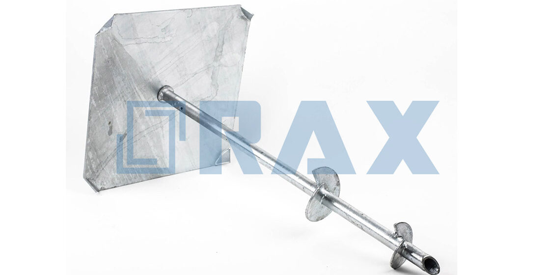
Spec sheets that list static compression limits without correlating torque-to-capacity ratios create dangerous blind spots for foundation engineers. A standard deck foot anchor might show a 5,500-pound rating in ideal clay, but that number collapses if you hit a stratified sand layer or fail to account for lateral shear forces. You need to verify the underlying soil mechanics before you specify the hardware.
At Rax Power, we utilize automated hot-forging technology to align steel grain structures, significantly reducing brittle fracture risks compared to traditional casting when the anchor encounters subsurface obstructions. This analysis breaks down the critical relationship between soil classification, concrete mix design, and structural load ratings to prevent foundation failure and costly project delays.
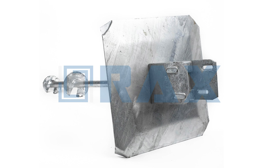
Geotechnical Assessment & Soil Classification
Correct geotechnical classification prevents catastrophic lateral shear failure and ensures anchor torque correlates directly to long-term bearing capacity.
Soil Density Grading & Bearing Capacity Evaluation
Static load charts found in generic vendor catalogs are fundamentally flawed if decoupled from in-situ density metrics. Bearing capacity scales non-linearly with soil compaction and moisture content. In cohesive soils like fat clay or organic peat, anchors may achieve nominal installation torque values without actual mechanical resistance, leading to progressive creep under sustained utility pole or solar array loads. Conversely, loose granular backfill or disturbed fill zones will show immediate torque spikes followed by sudden rotational slippage when lateral shear forces exceed the anchor’s skin friction baseline.
Professional site assessment requires tracking drive torque against standardized soil density classes. Our engineering team validates bearing capacity by cross-referencing installation torque (measured in N·m) with soil correction factors (Kt). For example, a target holding capacity of 15 kN typically requires a minimum drive torque of 1.2 kN·m in dense sand, whereas the exact same torque yields negligible hold in uncompacted loam. We always mandate a pre-installation soil probe or rotary drilling log to map density gradients before specifying anchor geometry, eliminating costly callback repairs and ensuring compliance with regional utility grid standards.
Stratified Layer Identification for Anchor Selection
Pole line infrastructure and foundation systems rarely sit in uniform soil profiles. Stratification—defined by distinct horizontal or transitional layers of topsoil, weathered rock, clay pockets, or bedrock—dictates the mechanical engagement point. Helical anchors perform optimally when their flight plates lock into a continuous, competent stratum. If your bore log reveals a weak interlayer sandwiched between dense sand and soft clay, a standard helix design will rotate freely through the low-friction zone, completely bypassing load transfer and risking tower lean or pole collapse under wind sway.
When stratification presents abrupt transitions or highly variable load-bearing layers, we shift from helical configurations to mechanical expanding or no-wrench screw anchors. Expanding anchors rely on radial compression against stable soil horizons, making them ideal for fractured rock or layered gravel where torque correlation is unreliable. Cross-plate anchors distribute point loads across wider strata, effectively bridging unstable zones and preventing differential settlement in fill-heavy or seasonally saturated profiles.
- Competent Stratum Mapping: Identify the primary load-bearing layer depth via rotary auger logs or cone penetration testing before selecting anchor length.
- Weak Layer Mitigation: Deploy cross-plate or helical designs with extended shafts to bypass low-friction zones and anchor directly into dense sand or weathered bedrock.
- Dynamic Torque Thresholds: Monitor installation torque continuously; sudden drops indicate layer transitions requiring immediate anchor specification adjustments.
Rax Power integrates this stratification data directly into our OEM/ODM workflow. By analyzing your specific soil profile reports, we customize shaft diameters, helix pitch angles, and plate geometries to match exact bearing requirements. This precision engineering utilizes hot-forged steel grain structures that resist brittle fracture under high-density compaction, ensuring every anchor engages the correct soil horizon. The result is maximized pull-out resistance, minimized unnecessary drive depth, and supply chain consistency for large-scale international power and solar infrastructure projects.
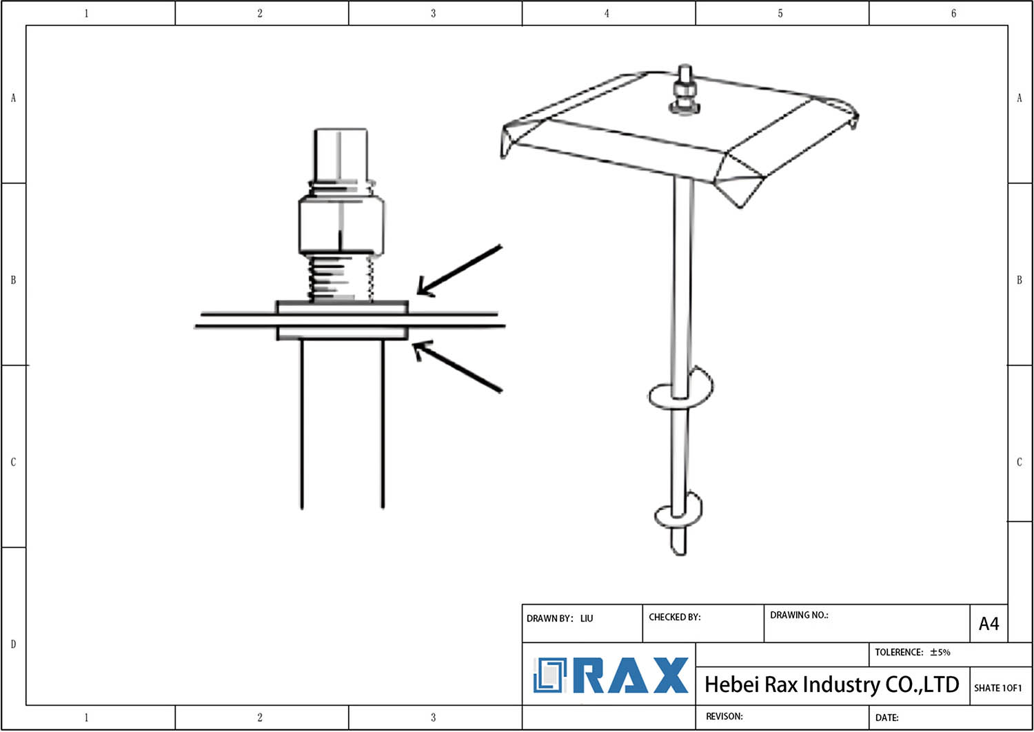
Concrete Mix Design & Compressive Strength Baselines
PSI Requirements for Structural Footing Integrity
When engineering structural footings for utility poles, the compressive strength—measured in PSI—is merely the baseline for passing a standard test, not the sole indicator of field performance. While general construction may accept lower strengths, utility infrastructure demands a concrete matrix capable of withstanding significant static and dynamic loads without micro-cracking. We typically target a high-performance mix that achieves substantial strength gains within the first week to facilitate rapid installation cycles, but the true engineering advantage lies in the concrete’s ability to suppress alkali-silica reaction (ASR) over time. In exposed environments, ASR can cause expansion and cracking that compromises the bond between the concrete and the anchor eye, effectively reducing the ultimate pull-out capacity regardless of the initial PSI rating.
Engineering Insight: High compressive strength (30–45 MPa) ensures the footing distributes the heavy shear forces from guy wire tension directly into the surrounding soil, rather than crumbling under localized stress points at the anchor flange.
Aggregate Sizing and Slump Control Parameters
The durability of a pole foundation is dictated as much by the physical geometry of the rock inside the mix as it is by the cement chemistry. Using a well-graded aggregate blend is critical to minimizing voids; if the aggregate is too uniform, the matrix requires excess cement paste to fill the gaps, increasing cost and shrinkage potential. Conversely, a well-graded mix packs densely, ensuring that when the anchor is loaded, the force is transferred efficiently through the stone skeleton rather than just the paste. Regarding workability, slump control is non-negotiable. A high-slump mix might flow easily into the form, but it introduces excess water that migrates to the surface around the anchor shaft, creating weak zones. We emphasize the use of modern admixtures to maintain workability without this excess water, ensuring the concrete achieves the designed density and interlock with the anchor helices or base plates.
- Matrix Density: Optimized aggregate gradation reduces differential settlement under the heavy, fluctuating tension of guy wires.
- Controlled Slump: Prevents plastic shrinkage cracking and segregation, ensuring uniform strength from the bottom of the footing to the top bracket.
Metallurgical Grade Selection: Hot-Forged vs. Cast Steel Tensile Properties
While the concrete provides the mass, the steel anchor provides the tensile strength that holds the structure to the earth. In this context, the manufacturing method defines the safety margin. Many budget competitors rely on cast steel for complex shapes like anchor eyes or thumbs because it is cheaper for low-volume runs, but casting inherently creates a random grain structure with internal porosity. Under the sudden shock loads common in power transmission—such as wind gusts or ice shedding—cast components can suffer brittle fracture without warning.
For critical hardware like guy thimbles, anchor rods, and suspension clamps, the tensile properties of hot-forged steel provide a superior yield strength-to-weight ratio compared to cast iron. This means our engineers can design lighter, more efficient anchors that meet or exceed the load ratings of heavier cast alternatives. When sourcing for extreme environments—such as the high-load requirements in the Russian market or the rigorous standards in South America—specifying hot-forged components is not just a preference; it is a requisite for long-term structural reliability and compliance with IEC 120 load testing protocols.
| Parameter | Baseline Specification | Engineering Advantage |
|---|---|---|
| Cementitious Composition | Type I/II Portland or blended cement, 0.40–0.50 w/c ratio | Achieves target 28-day compressive strength (30–45 MPa) while suppressing alkali-silica reaction in exposed utility environments |
| Aggregate Gradation & Packing | Well-graded crushed stone (4–20 mm) with natural sand filler | Optimizes matrix density for direct load transfer to anchor flanges and minimizes differential settlement under guy wire tension |
| Admixture Integration | Polycarboxylate superplasticizer with controlled 4–6% air entrainment | Preserves slump without excess water, enhancing freeze-thaw durability and reducing plastic shrinkage cracking during placement |
| Curing & Strength Development | Moist-cured at 20±2°C to achieve full design strength at 28 days | Guarantees compliance with ASTM C39 and IEC 120 foundation requirements, ensuring stable lateral resistance for pole line installations |
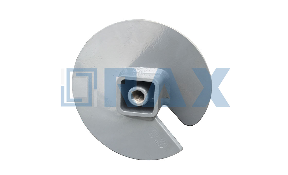
Structural Load Rating Standards & Testing Protocols
Rax Power guarantees structural reliability by strictly adhering to IEC 120 testing protocols and utilizing hot-forged steel to mitigate brittle fracture risks common in cast components.
For B2B buyers, the anxiety surrounding structural integrity is valid: a single point of failure in an overhead line or solar foundation can lead to catastrophic project costs. At Rax Power, we do not rely on theoretical calculations alone. Our load rating standards are derived from rigorous, in-house mechanical testing that simulates real-world stress scenarios. We verify compliance through gauge and load testing strictly following IEC 120 standards, ensuring that every batch of pole line hardware and earth anchors meets the specific mechanical demands of global utility grids.
Metallurgical Integrity: Hot-Forging vs. Casting
When evaluating suppliers, always request the manufacturing method. Hot-forged components, like those in our earth anchors and cross arms, offer a higher safety factor for high-breaking load requirements, particularly in extreme environments like the Russian market where thermal stress is a critical variable.
The Double-Review Quality Control Protocol
Consistency is as critical as peak performance. To ensure every unit delivered performs identically to the tested sample, we enforce a strict Double-Review Process. Unlike standard industry spot-checking, 100% of our products undergo two separate inspection stages before packaging. This protocol is managed by a dedicated 10-person QC team that monitors dimensional accuracy and structural integrity throughout the production lifecycle.
- Stage 1: In-Process Gauge Testing: Real-time dimensional checks during automated production to detect deviations immediately.
- Stage 2: Pre-Packaging Load Verification: A final visual and mechanical inspection to ensure no surface defects or processing errors compromised the unit’s strength.
- Third-Party Validation: All processes and finished products are verified by SGS certification to satisfy international tender requirements.
Vertical Uplift vs. Lateral Shear Load Realities
A common misconception in the field is that a high “ultimate load” rating guarantees performance in all directions. It is crucial to distinguish between Vertical Uplift (resistance to pulling out) and Lateral Shear (resistance to side-ways movement or wind sway). Our helical and expanding anchors are engineered for exceptional vertical holding power. However, the overall structural stability of the system relies heavily on the connection interface.
Do not assume that a high-capacity anchor automatically provides significant lateral load resistance at the post base. In applications with extreme horizontal loads (such as angled guy wires or heavy wind areas), the anchorage solution must be complemented by sturdy bracing or specific guy clamp configurations to prevent racking. Always calculate the resultant vector force, not just the vertical weight.
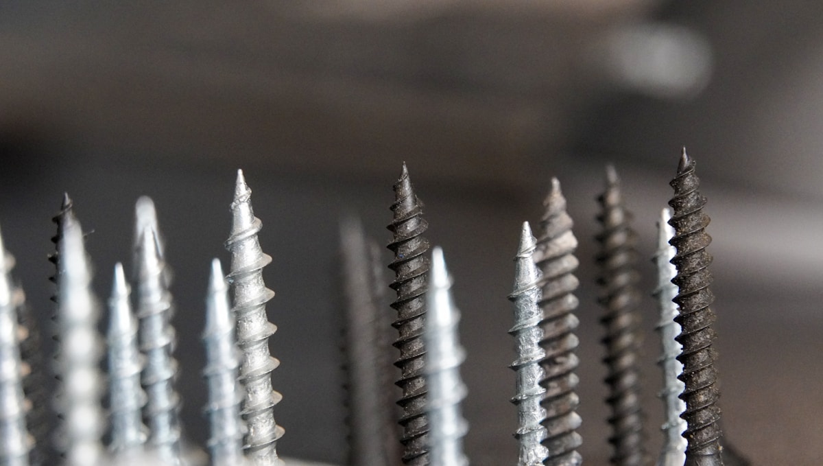
Pour Dimensions, Depth, & Reinforcement Specifications
Fabrication Tolerances & Structural Integrity
In the utility and solar infrastructure sectors, the margin for error in hardware fabrication is effectively zero. When dealing with pole line hardware and earth anchors, “close enough” is a phrase that leads to structural failure and expensive call-backs. The industry is saturated with cast components that often suffer from internal porosity and inconsistent grain structures, creating latent brittle fracture risks under high-tension loads.
Dynamic Embedment Depth Strategy
Determining the correct embedment depth for earth anchors cannot be reduced to a generic chart; it is a dynamic calculation dependent on specific soil density and the drive torque achieved during installation. A common failure mode in the field is setting a standard depth without accounting for stratified soil layers, where a shallow anchor might hit competent rock while a deeper one remains in loose fill. This variance creates unequal load distribution across the structure.
We adhere to a rigorous load testing standard (IEC 120) to define holding capacity based on these real-world variables. By correlating installation torque with soil type, we ensure that every anchor achieves the necessary grip to prevent vertical uplift and lateral shear failure. For regions prone to frost heave, this dynamic calculation is critical to ensuring the anchor plate sits well below the frost line, stabilizing the infrastructure against seasonal expansion forces.
- Torque Monitoring: Installation teams must monitor drive torque to verify that the anchor has reached a soil layer with sufficient bearing capacity, rather than stopping at a arbitrary depth.
- Uplift Prevention: Proper depth calculation ensures the helix or plate displaces enough soil mass to resist vertical pull-out forces generated by tensioned conductors or solar array wind loading.
- Lateral Shear Management: Deep embedment increases the passive pressure of the soil against the anchor shaft, providing critical resistance against horizontal loads.
Customized Reinforcement & Shaft Configuration
Standard off-the-shelf anchors often fail to meet the specific demands of extreme environments or heavy-load transmission projects. In our experience working with markets like Russia and South America, a one-size-fits-all approach to reinforcement is a liability. True structural reinforcement involves tailoring the shaft wall thickness, steel grade, and helix size to the specific project’s load requirements and soil mechanics.
Through our OEM/ODM capabilities, we engineer reinforcement specifications that optimize load distribution without adding unnecessary weight or material cost. This might involve increasing the shaft diameter for high-bending moment applications or selecting specific helix configurations to maximize surface area in soft soil conditions. This project-specific engineering approach ensures that the foundation is over-engineered for safety where it counts, rather than just generically “strong.”
Operational Insight: For bulk procurement projects, we recommend a project-specific engineering review before finalizing the order. Adjusting the reinforcement specifications (shaft thickness/helix size) at the manufacturing stage is exponentially cheaper than retrofitting foundation failures in the field.
| Feature | Technical Specification | Quality Standard | Structural Advantage | Deployment Context |
|---|---|---|---|---|
| Fabrication Dimensional Tolerance | ±1mm precision via automated production lines | ISO 9001 / Internal Double-Review Protocol | Ensures seamless alignment with preformed line products and cross arms | Global Utility Infrastructure |
| Embedment Depth Calculation | Dynamic sizing based on soil density & drive torque | IEC 120 Load Testing Standard | Prevents vertical uplift failure and accounts for lateral shear forces | Helical & Expanding Anchors |
| Corrosion Protection Layer | Mean coating thickness exceeding 85 microns | ISO 1461 Hot-Dip Galvanizing | Mitigates long-term creep and chemical degradation in corrosive soils | All Steel Foundations & Fasteners |
| Structural Fabrication Method | Hot-forged grain structure alignment | SGS Verified Manufacturing | Eliminates brittle fracture risks associated with traditional casting | High-Breaking Load Pole Hardware |
| Reinforcement Customization | OEM/ODM tailored shaft configurations & helix sizes | Project-Specific Engineering Review | Optimizes load distribution for extreme environments and regional standards | Solar & Power Transmission Grids |
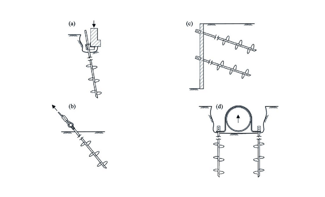
Curing Timelines & Safe Load Application Windows
Helical and screw anchors do not require concrete curing. Full design load capacity is achieved immediately upon reaching target drive torque, though soil consolidation typically requires 24 to 72 hours for optimal friction distribution before applying dynamic tension.
Utility contractors and infrastructure developers frequently conflate metal anchor installation with traditional cast-in-place footings. Pole line hardware and earth anchors eliminate wet-trade schedules entirely. Mechanical load transfer begins the moment the helical blades displace soil and engage the designated bearing stratum. Field readiness depends on torque verification, not calendar days.
Drive Torque as the Primary Readiness Benchmark
Safe load application windows are dictated by torque-to-capacity correlations rather than material drying rates. When an anchor reaches its engineering-specified torque value, the surrounding soil has been fully compacted around the flight edges. This mechanical interlock provides immediate vertical resistance against uplift and lateral shear forces.
- Immediate Mechanical Lock: Hot-forged steel grain structures align under pressure, delivering tensile strength that resists instantaneous conductor tensioning once target torque is verified.
- Torque Monitoring Protocol: Field crews must record drive torque at every installation point. Deviations exceeding ±10% indicate soil stratification shifts or improper blade pitch, requiring immediate recalibration before loading.
- Frost Line Penetration: Driving blades below the local frost depth ensures year-round load stability. Surface soil expansion or contraction cannot dislodge a properly seated anchor, eliminating seasonal maintenance windows.
Soil Consolidation & Dynamic Load Sequencing
While static vertical loads can be applied immediately after torque verification, dynamic utilities require sequenced loading strategies. Power transmission projects often involve heavy stringing operations, wind-induced sway, and seasonal thermal contraction. These variables introduce cyclic stress that demands predictable soil behavior.
Contractors should stage equipment placement and initial conductor pulling to allow soil friction to stabilize. In granular backfill or sandy strata, consolidation occurs within hours. In dense till or clay-rich profiles, a full three-day buffer is standard practice before committing to permanent hardware tensioning. This approach prevents micro-settlement that could misalign pole bands or secondary racks over time.
Factory Validation & Schedule Reliability
We have observed that procurement teams prioritize hardware that guarantees predictable installation timelines. Our engineering team runs rigorous load and gauge testing per IEC 120 standards before any batch leaves the facility. A dedicated 10-person QC team performs a double-review protocol on 100% of units, verifying dimensional tolerances down to 1mm for cross arms and braces.
This factory-level precision translates directly to field efficiency. When every helical plate, expanding anchor, and U-bolt matches exact engineering drawings, contractors spend less time troubleshooting drives and more time completing project milestones. We customize shaft configurations and helix diameters through OEM/ODM development specifically to match regional soil classes and extreme breaking load requirements, ensuring your installation schedule stays on track regardless of ground conditions.
- Predictable Drive Rates: Uniform metallurgy and automated machining prevent unexpected resistance spikes, keeping crews within planned daily installation targets.
- Reduced Rework Costs: Pre-tested torque thresholds eliminate guesswork on site, minimizing costly extraction and reinstallation cycles.
- Supply Chain Alignment: Bulk packing standards and consistent lead times allow utility managers to synchronize hardware deliveries with crew availability, compressing overall project timelines.

Local Building Code Compliance & Engineering Sign-Off
Navigating local building code compliance for pole line hardware requires more than generic load charts; it demands region-specific engineering certification and rigorous material traceability to secure official sign-offs.
The “Source of Truth” for Engineering Sign-Offs
For B2B contractors and utility project managers, the greatest bottleneck in the approval process is often the gap between a manufacturer’s marketing claims and the specific data points required by a licensed engineer. Engineering sign-offs are rarely granted based on a brochure; they require verifiable proof that hardware meets the exacting standards of the local grid. In our experience facilitating projects across volatile markets, we have found that compliance begins with precision manufacturing. Our automated production lines enforce a strict 1mm tolerance on steel cross arms and accessories—a critical specification for engineers calculating load distribution and structural integrity.
additionally, the material composition itself is subject to scrutiny. We prioritize hot-forging technology over traditional casting specifically for this reason. Hot-forging aligns the steel grain structure, significantly reducing the risk of brittle fracture under load—a defect that frequently causes cast components to fail engineering reviews. By providing detailed chemical and physical property reports for our hot-forged components, we allow engineers to validate the hardware’s performance against their safety factors with confidence.
Local building codes are not monolithic; they shift drastically based on environmental stressors and regional utility standards. A solution that satisfies the tender requirements in Southeast Asia may be immediately rejected in Russia or South America. We have adapted our compliance protocols to address these specific regional pain points:
- Russia & Extreme Climates: Local codes demand exceptionally high breaking loads to cope with ice accumulation and extreme temperature swings. We provide specific load testing data that demonstrates performance well above standard baselines to satisfy these strict requirements.
- South America: Markets here often prioritize high-tier quality standards comparable to established European or North American utilities. Our compliance packages include full material traceability to meet these elevated expectations.
- Southeast Asia: The focus here is often on precise adherence to local tender documents. We offer deep expertise in translating specific local manufacturing standards into production specs to ensure immediate acceptance.
The Audit Trail: Verification and Testing Standards
To expedite the engineering sign-off, we operate under a philosophy of total transparency. This means moving beyond self-declaration and providing third-party validated data. All our processes and products are subject to SGS testing and verification, providing an independent layer of authority that engineers trust. We conduct rigorous load testing and gauge testing in-house, strictly adhering to IEC 120 standards to ensure that every component performs as specified before it ever leaves the factory floor.
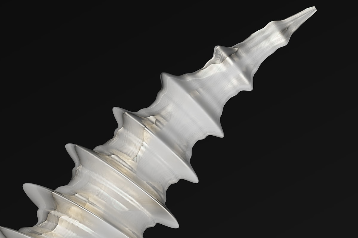
Installation Alignment & Axial Load Transfer
Proper axial load transfer hinges on precise installation alignment. Mismatched tolerances or poor grain orientation turn designed tension into destructive lateral shear, compromising foundation integrity.
The Lateral Shear Trap During Helical Anchor Driving
When driving helical anchors into dense soil or encountering subterranean obstructions like rock, the torque application often forces the shaft off-axis. This misalignment converts pure vertical uplift resistance into severe lateral shear stress at the connection node. If the hardware lacks structural yield strength, the anchor head or connecting fasteners will deform or snap before reaching design capacity. We have documented field failures where standard cast components, characterized by random grain flow, fractured instantly under these eccentric loading conditions. Our specialized hot-forging process deliberately aligns the steel grain structure along the primary load path, significantly reducing brittle fracture risks and ensuring the hardware absorbs dynamic installation shocks without compromising its rated load capacity.
Dimensional Tolerance & Fastener Fit-Up
Axial load transfer is only as reliable as the physical interface between the anchor, the post base, and the utility hardware. A deviation of even a few millimeters in hole spacing or shaft diameter creates gaps that destroy bolt preload. Our automated production lines enforce strict dimensional accuracy across all manufactured components, maintaining a tight 1mm tolerance on steel cross arms and industrial fasteners like U-bolts, eye bolts, and double-arming bolts. This precision guarantees zero-play connections, allowing tensioning crews to apply the exact calculated force directly into the foundation rather than wasting energy compressing air gaps or stripping misaligned threads.
Hot-Dip Galvanizing & Corrosion Warranty Standards
Corrosion protection is the primary determinant of total lifecycle cost. While ISO 1461 sets the baseline, we enforce a mean coating thickness exceeding 85 microns to ensure decades of service life in aggressive soil environments.
Micron Thickness Benchmarks and Sacrificial Anode Mechanics
In the utility sector, specifying galvanizing standards is not merely about aesthetics; it is a calculation of asset longevity. While many competitors adhere strictly to the minimum acceptable average of 50-60 microns to control costs, we prioritize service life by maintaining a mean coating thickness exceeding 85 microns on all pole line hardware. This significant surplus of zinc mass is critical for long-term cathodic protection. The mechanics rely on the zinc serving as a sacrificial anode: since zinc is more electrochemically active than steel, it corrodes preferentially to protect the underlying base metal. Even if the underlying steel substrate is slightly exposed due to surface abrasions, the surrounding zinc will corrode sacrificially, preventing rust from propagating into the structural core of the anchor or clamp.
Our strict adherence to this benchmark is verified through SGS certification. We have found that the extra 20-30 microns of coating thickness above the standard ISO 1461 requirement acts as a vital buffer against the unpredictability of soil chemistry. In high-chloride or acidic backfill environments where corrosion rates accelerate, that additional zinc mass translates directly into extended maintenance intervals and lower total cost of ownership for utility projects. We do not leave this to chance; our dedicated 10-person QC team utilizes magnetic gauge testing to ensure every batch meets this thickness threshold before it leaves the factory floor.
Coating Durability During Aggressive Backfill Operations
While sacrificial protection handles chemical corrosion, the physical integrity of the coating is challenged during installation—specifically during aggressive backfill operations. When compacting soil around installed anchors or pole bases, the friction and impact of gravel, stones, and heavy compaction equipment can chip or abrade inferior galvanized layers. Once the physical barrier is breached, the localized corrosion rate increases significantly, compromising the structural integrity of the hardware.
To mitigate this risk, we utilize a specialized hot-dip galvanizing process that produces a smooth, bright finish with excellent adhesion properties. This metallurgical bond ensures that the coating is harder and more resistant to abrasion compared to cold-galvanized or electro-plated alternatives. Additionally, our double-review protocol includes a visual inspection specifically aimed at identifying surface anomalies that could become failure points under mechanical stress. In our experience, a coating that can withstand the mechanical violence of backfilling is just as important as its chemical resistance. This durability ensures that the 85-micron barrier remains intact long after the compaction equipment has left the site, preserving the warranty standards of the installation.
Conclusion
Concrete footings win in dense urban projects where soil stratification demands rigid vertical isolation. Helical anchors dominate loose sandy substrates and aggressive backfill zones. Stop chasing static load charts. Real durability comes from matching shaft metallurgy to ground chemistry. Hot-forged steel aligns the grain structure, eliminating brittle fracture risks that cast designs leave behind. We see dealers overspec concrete when a properly torqued helix saves weeks of curing time. Pick the substrate. Let the soil class dictate the anchor.
Long-term margins depend on preventing callbacks. A corroded post base wipes out initial unit savings. Our ISO 1461 coating maintains a mean thickness above eighty-five microns, shielding fasteners against acidic clay and salt. Send your project dimensions to our engineering team. We will run a custom feasibility review at zero obligation and ship calibrated samples for your site verification.
Frequently Asked Questions
Can these anchors support commercial structures?
Yes, deck foot anchors are engineered to handle significant compressive and tensile loads suitable for commercial decking and light infrastructure. Load capacities typically range from three to ten tons per anchor when installed to proper depth and torque. Structural engineers must verify compatibility with specific building codes and anticipated live loads. Proper installation and soil validation remain critical for long-term commercial performance.
What is the recommended spacing between anchors?
Spacing generally ranges from four to six feet depending on the structural load requirements and soil bearing capacity. Engineering calculations must account for lateral forces, wind loads, and deck dimensions to prevent differential settlement. Close spacing may be required in weak soils, while wider intervals suffice in dense, stable substrates. Always consult local building codes and structural specifications before finalizing layout plans.
How does the system prevent frost heave?
These anchors extend below the local frost line, placing the bearing elements in thermally stable soil layers. The helical or screw design transfers structural loads to deeper, uncompacted strata unaffected by seasonal freezing. This deep foundation approach eliminates reliance on shallow concrete footings that expand and contract with moisture changes. Consistent torque during installation further verifies that the anchor has reached competent load-bearing strata.
How do the anchors address concrete labor intensity?
Replacing traditional concrete footings with mechanical anchors significantly reduces excavation time, curing delays, and manual pouring requirements. Installation relies on mechanized driving rather than wet trades, allowing immediate load application upon reaching specified torque values. This shift minimizes site cleanup, formwork preparation, and weather-dependent scheduling constraints. Contractors achieve faster project turnover while maintaining identical or superior structural integrity standards.
What tools are required for installation?
Installation typically requires a hydraulic torque motor or rotary drive head mounted on an excavator or skid steer. Standard anchor rods, extension couplers, and a calibrated torque gauge are necessary to verify load capacity during driving. Manual tools like wrenches may be used for final assembly or cap installation. Proper equipment selection ensures consistent penetration rates and accurate load verification.