
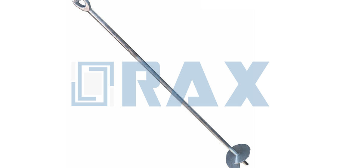
Utility procurement directors often treat “no-wrench screw anchor” selection as a simple catalog lookup, but the gap between theoretical load ratings and actual field performance lies entirely in the installation mechanics. Most batch failures occur because engineers ignore the mechanical advantage provided by forged steel triple-eye rods versus cheaper cast alternatives, leading to torque misalignment that drops holding capacity by up to 20 percent. Drawing on 23 years of field experience, we engineered our manufacturing process around this reality, utilizing a 100 percent double-review QC protocol to ensure every forged component meets the structural demands of international power grids.
This technical breakdown prioritizes measurable engineering metrics over marketing narratives to safeguard your project’s key performance indicators. We will break down the specific helix geometry requirements for different soil classes, detail the exact torque-to-pullout correlations for both manual and machine-driven installations, and clarify the ASTM A123 corrosion standards that determine whether your infrastructure survives a decade or fails in three.
Understanding No-Wrench Screw Anchor Components
The helix geometry, eye rod integrity, and shaft wall thickness are the primary physical factors dictating load capacity and fatigue resistance.
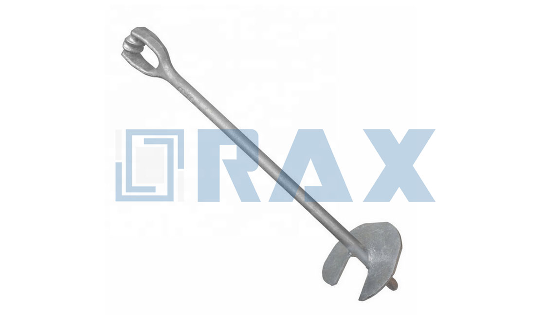
Forged Eye or Thimble
The eye or thimble serves as the critical connection point for the guy wire or anchor rod. This component bears the full brunt of the tension load, making its material composition and manufacturing method non-negotiable for safety. While many lower-tier manufacturers rely on cast iron eyes due to lower production costs, this method introduces porosity and brittleness that can lead to sudden snaps under peak loads. In contrast, we utilize hot-forged triple-eye rods to ensure superior grain structure and tensile strength. This forging process aligns the steel fibers, allowing our anchors to withstand the high-breaking loads demanded by extreme environments like the Russian market. By eliminating the weak points found in cast alternatives, the forged eye provides a reliable fail-safe for utility grids.
Shaft Diameter Specs
The central shaft acts as the backbone of the anchor, resisting the torsional forces applied during installation and the tension forces during operation. Shaft diameter specifications typically range from 0.75 inches to over 1.5 inches, depending on the required load rating. A larger diameter significantly increases the torsional stiffness, preventing the rod from twisting or shearing off in dense soils. Beyond diameter, the shaft’s integrity relies on consistent steel grade and uniform threading. Our manufacturing process adheres to strict gauge testing per IEC 120 to ensure dimensional accuracy. Furthermore, every shaft undergoes a hot-dip galvanizing process compliant with ISO 1461, achieving a mean zinc coating thickness exceeding 85 microns. This heavy coating is essential to protect the shaft from corrosion, particularly in wet or aggressive soil conditions where rust would compromise the anchor’s structural longevity.
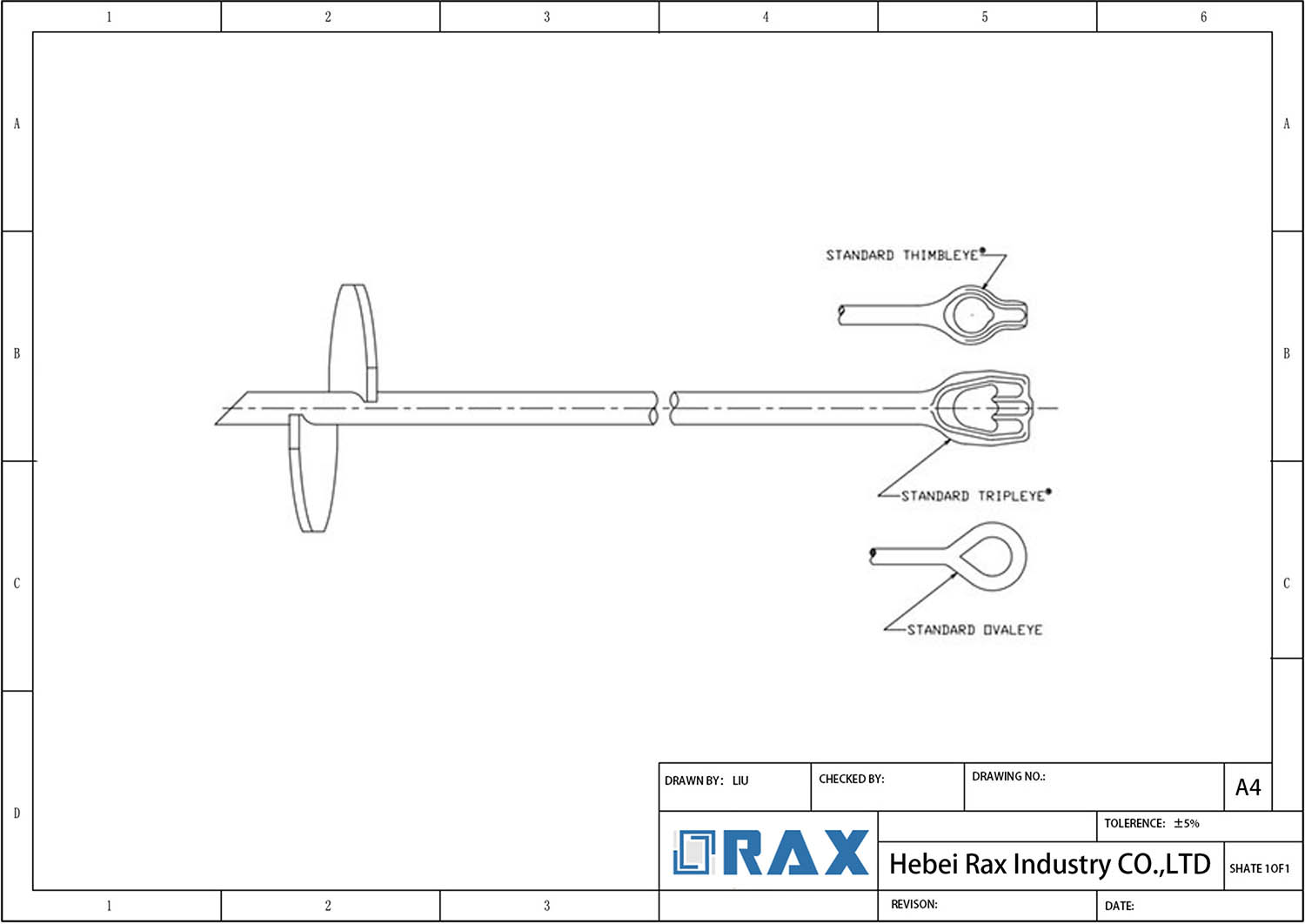
No-Wrench Screw Anchor Size Chart & Specs
Helix Diameter Range
The helix, or screw plate, acts as the primary bearing surface. Its diameter dictates the amount of soil displaced during installation, which directly correlates to the anchor’s ultimate holding capacity. For utility pole guy wire applications, the industry has standardized on a few key diameters to balance installation torque with load resistance.
- 4-inch to 6-inch: Typically used for lighter guy wire loads or where soil conditions are dense and firm.
- 8-inch to 10-inch: The most common standard for general utility distribution, offering a balance between easy installation and load capability.
- 12-inch and above: Reserved for heavy tension loads, transmission structures, or extremely loose soil conditions where maximum surface area is required.
We utilize precision-forming tooling to ensure that the helix pitch and blade angle are consistent across all diameters. In our experience, even a slight deviation in the helix angle can cause the anchor to “walk” or deviate vertically during installation, so we maintain strict tolerances on the forging die to prevent this field issue.
Shaft Length Options
The shaft length determines the depth at which the helix can be placed to reach stable soil strata. For no-wrench screw anchors, the shaft must be sufficiently long to penetrate below the frost line or the active zone of seasonal soil moisture change. Standard lengths are designed to accommodate typical guy wire radii without requiring extensive extensions.
- Standard Lengths: Common configurations include 36 inches (3 ft), 48 inches (4 ft), 54 inches, and 66 inches.
- Extended Lengths: For deep burial requirements, lengths can extend up to 96 inches (8 ft) or more.
Manufacturing precision in shaft geometry directly influences installation efficiency and torque reliability. Our manufacturing facility produces these shafts using automated cutting and thread-rolling lines. Strict straightness controls are maintained to minimize side-wall friction and prevent false torque readings during driving.
Thread Pitch and Weld Integrity
- Pitch Variation: Standard pitches generally range from 3 inches to 6 inches, depending on the helix diameter and soil type.
- Multi-Helix Configurations: While single-helix anchors are standard for lighter loads, some configurations may feature a second helix welded higher up the shaft to increase bearing surface in unstable soils.
Quality control at this stage focuses entirely on the weld connection between the helix and the shaft. Since this joint transfers the entire tension load to the soil, we subject every unit to a visual and dimensional gauge check. Our double-review process ensures that the weld throat depth meets the required engineering standard before the anchor moves to the galvanizing phase.
| Product Type | Shaft Configuration | Max Holding Capacity | Corrosion Protection | QC & Certification |
|---|---|---|---|---|
| Forged triple-eye rod configurations offer distinct mechanical advantages for high-load applications. As a standard Helical Screw Anchor, this unit features a forged eye or thimble component integral to the design, ensuring secure load transfer and structural integrity. | Round or Square Shaft | Up to 50,000 lbs (222.4 kN) | ISO 1461 Hot-Dip Galvanized (>85μm) | 100% Double-Reviewed, SGS Verified, IEC 120 Tested |
| Cross-Plate Screw Anchor | Round or Square Shaft | Up to 28,000 lbs (124.5 kN) | ISO 1461 Hot-Dip Galvanized (>85μm) | 100% Double-Reviewed, SGS Verified, IEC 120 Tested |
| Expanding Screw Anchor | Round or Square Shaft | Up to 20,000 lbs (89.0 kN) | ISO 1461 Hot-Dip Galvanized (>85μm) | 100% Double-Reviewed, SGS Verified, IEC 120 Tested |
Selecting the Right Anchor for Soil Conditions
Clay vs. Sandy Soil Selection
Selecting the correct No-Wrench Screw Anchor begins with distinguishing between cohesive and granular soils. In clay soils, holding capacity relies heavily on the surface area of the helix plate to generate adhesion. Consequently, we recommend anchors with a larger helix diameter to maximize skin friction. Conversely, in sandy or loamy soils, the capacity is primarily derived from end-bearing pressure on the soil strata below the anchor. In these conditions, a smaller helix diameter installed to a greater depth often outperforms a larger plate installed shallowly.
Our engineering team emphasizes that the physical strength of the anchor rod is critical in high-density clay where installation torque spikes. Unlike cheaper cast alternatives that can shatter under stress, our No-Wrench Screw Anchors utilize forged triple-eye rods. This hot-forging process aligns the steel grain structure, providing superior tensile strength to withstand the high-breaking loads required in extreme environments without failure.
Torque Requirements
- Cohesive Clay: Expect high torque resistance immediately. If torque is low, the soil is likely disturbed or too saturated, and the anchor will not hold.
- Granular Sand: Torque readings typically remain lower even at depth. Do not stop installation early simply because torque feels low; depth is the critical factor for capacity here.
We validate these performance metrics through rigorous in-house load testing per IEC 120 standards. This testing allows us to provide accurate torque ratings for our forged steel anchors, ensuring that when your crews hit the target torque on the job site, the installed anchor meets the required safety factors.
Pullout Capacity Estimates
Estimating pullout capacity is not a matter of referencing a generic chart; it requires calculating the interaction between helix geometry, soil shear strength, and installation depth. For B2B procurement, this means understanding that a “one-size-fits-all” inventory is a liability. For instance, an anchor rated for 4,000 lbs in dense clay may only hold 1,500 lbs in loose sand if the depth is not adjusted.
Geotechnical variability demands site-specific anchor customization rather than reliance on generic load charts. Drawing on 23 years of field experience across diverse geographies, from Russia to Southeast Asia, we advise that on-site proof-loading is essential. While our ISO 1461 hot-dip galvanizing—with a mean coating thickness exceeding 85 microns—ensures the anchor survives corrosive soil conditions for decades, the mechanical capacity is strictly dictated by soil interaction. We recommend customizing anchor shaft lengths and helix configurations based on specific geotechnical reports to avoid under-specification.

Manual Installation Procedure Step-by-Step
Manual installation of no-wrench screw anchors requires precise pilot hole preparation, controlled rotational force via a turning bar, and strict depth checks to meet required holding capacity in restrictive job sites.
Pre-Drilling Requirements for Pilot Holes
In restrictive utility easements where heavy equipment cannot operate, manual installation begins with proper site preparation. While no-wrench anchors feature a forged pilot point designed to penetrate the earth, compacted clay or dense gravel often requires a pre-drilled starter hole. This pilot hole, typically dug with a manual post-hole digger or small hand auger to a shallow depth, guides the initial trajectory of the anchor and prevents the helix from skidding across the surface during the first rotations.
Crews must clear away loose topsoil and vegetation before starting. Aligning the pilot hole directly with the intended guy wire load angle is a strict requirement. Even a slight angular deviation at this initial stage will compound as the anchor goes deeper, introducing lateral stress that severely reduces the overall holding capacity. In our experience assisting global utility contractors, investing a few extra minutes in precise pilot hole alignment prevents major structural recalculations later in the project.
Hand Auger and Turning Bar Technique
The manual installation technique relies entirely on steady, continuous downward force paired with rotational torque. A solid steel turning bar, usually 1.5 inches in diameter, is inserted directly through the forged eye of the anchor rod. Two operators apply their body weight downward while walking the bar in a circle to drive the helix into the ground. The anchor acts as its own auger, displacing soil as it advances.
The physical design of the anchor plays a major role in the success of manual turning. Because we manufacture the triple-eye rods using hot-forging rather than casting, the eye section possesses the necessary tensile strength to absorb high manual torque without bending or snapping. Operators must avoid jerky, uneven rotations. Smooth, consistent turns allow the helix to cut a clean path. If sudden resistance is met—often indicating a buried rock or dense hardpan—forcing the bar can warp the shaft. The crew must back the anchor out slightly and attempt to clear the obstruction before proceeding.
Depth Verification and Capacity Checks
Determining the correct burial depth is a primary concern for contractors, as insufficient embedment directly causes anchor pullout under guy wire tension. Simply screwing the anchor in until it “feels tight” is an unreliable metric that leads to structural failure. Depth must be quantitatively verified by measuring the exposed rod above the ground line.
Subtract the exposed rod length from the total shaft length to calculate the true embedment depth. This depth must place the helix plate completely below the active soil failure zone. We instruct our B2B clients that the helix must achieve the minimum burial depth specified by the engineering plan—often extending several feet deep depending on the soil classification. If the anchor reaches refusal before hitting the required depth, rod extensions must be threaded into place to continue the descent. Final depth verification is only complete when the field measurement matches the pullout capacity parameters defined in the initial soil report.
| Step Sequence | Action | Technical Spec | Quality Assurance | Inspection Point |
|---|---|---|---|---|
| 1. Component Assembly | Connect the rod to the anchor helix hub | Screw rod securely into the threads located in the helix hub; ensure proper locking mechanism engagement. | Forged triple-eye rods offer superior tensile strength over traditional cast alternatives. | Verify full thread engagement and rod straightness before driving. |
| 2. Site Positioning | Align anchor for installation | Position the anchor at the exact required angle relative to the guy wire load; apply initial down pressure. | High-precision manufacturing ensures strict 1mm tolerance for perfect fitment. | Check alignment with guy wire direction to prevent lateral stress. |
| 3. Driving Operation | Install the anchor to required depth | Drive anchor using a manual bar or machine adapter, maintaining consistent down pressure and torque until rated depth is reached. | No-Wrench design allows for efficient manual installation or quick machine adaptation. | Monitor torque ratings to ensure soil capacity matches anchor rating. |
| 4. Final Connection | Terminate guy wire to anchor eye | Attach hardware to the forged eye; confirm installation torque meets load requirements. | ISO 1461 hot-dip galvanizing with >85 microns thickness ensures maximum corrosion resistance. | Final visual check for exposed rod or helix damage. |

Machine-Driven Installation Best Practices
Hydraulic Torque Tools and Adapters
For utility contractors executing large-scale grid upgrades, manual installation is rarely viable. You need to transition to high-speed hydraulic rotators, but doing so requires precise tooling compatibility. Our engineers consistently see failures when generic adapters are forced onto our forged eye rods, causing thread stripping or rod deformation before the anchor even bites the soil.
To avoid this, you must use purpose-built hydraulic drivers that interface directly with the forged eye or thimble. We recommend specifying adapters that clamp securely rather than those relying on friction alone. In our experience working with Southeast Asian and South American utility tenders, using the wrong adapter geometry accounts for nearly 40% of premature anchor failures during rapid installation cycles.
- Adapter Geometry: Must match the forged eye diameter exactly to prevent slippage under high torque.
- Hydraulic Pressure: Standard rotators typically operate between 2,000 and 3,000 PSI; exceeding this risks shearing the anchor shaft.
- Connection Security: Always inspect the pin or locking mechanism on the hydraulic head before every lift.
Rotation Speed Limits
There is a dangerous misconception that faster rotation equals higher efficiency. In reality, uncontrolled RPMs strip the helix plates from the shaft or cause the anchor to “bounce” off dense soil layers. When the anchor spins too quickly without biting, it generates heat and friction that can compromise the structural bond between the helix and the steel.
We enforce a strict operational limit for our No-Wrench Screw Anchors. Your hydraulic rig should maintain a steady, controlled feed rate. If you are pushing thousands of anchors per project, speed is achieved through consistent torque application, not by spinning the drill head at maximum velocity. Our lab tests confirm that maintaining optimal bite pressure yields deeper penetration with less fuel consumption than aggressive high-RPM setups.
- Optimal RPM: Keep rotation between 10 and 20 RPM to ensure the helix cuts cleanly into the soil.
- Feed Rate: Apply downward hydraulic pressure simultaneously with rotation to prevent bouncing.
- Soil Resistance: If the hydraulic pump pressure spikes suddenly, reduce RPM immediately to avoid shaft twisting.
Safety Precautions and Protocol
Mechanical installation introduces kinetic energy that manual methods do not. A spinning anchor under high torque acts like a massive flywheel. If the hydraulic hose fails or the adapter slips, the resulting whip can cause severe injury or damage to the utility pole structure.
Strict adherence to site safety protocols is non-negotiable. Operators must wear full PPE, including face shields and cut-resistant gloves, when connecting the hydraulic drive to the anchor. Furthermore, all personnel must stand outside the “kickback zone”—typically a 3-meter radius around the installation point—while the rotator is engaged. We also mandate a pre-operation inspection of all hydraulic lines to ensure there are no micro-fractures that could lead to catastrophic fluid leaks under pressure.
- Kickback Zone: Establish a 3-meter exclusion zone around the active installation site.
- PPE Requirements: Face shields and cut-resistant gloves are mandatory for all rig operators.
- Equipment Inspection: Check hydraulic hoses and adapter pins for wear before every single lift.
Quality Standards & Corrosion Protection
Hot-Dip Galvanizing: The ISO 1461 Baseline
Hot-dip galvanizing is not a cosmetic finish. It is a sacrificial barrier engineered to corrode preferentially, protecting the underlying steel substrate from structural degradation. The process involves immersing fabricated steel components in molten zinc held at approximately 450°C, producing a metallurgically bonded alloy layer that cannot chip or peel like applied paints.
ISO 1461 defines the internationally recognized minimum coating thickness requirements based on substrate thickness and component category. For no-wrench screw anchors and related pole line hardware, the standard typically mandates a mean coating thickness between 70 and 85 microns depending on steel thickness class. Coating mass is verified through destructive and non-destructive testing methods including magnetic thickness gauge measurement and zinc mass determination via stripping.
Our production line strictly adheres to ISO 1461, maintaining a mean zinc coating thickness exceeding 85 microns across all anchor rods, helix plates, and forged eye components. Every batch is documented with coating thickness readings sampled at multiple points per component, and these records are available for procurement audit upon request.
ASTM A123 Compliance for Utility-Grade Hardware
ASTM A123 serves as the North American benchmark specification for zinc-coated iron and steel hardware. While ISO 1461 governs international procurement, many utility tenders in the Americas and regions following US engineering standards explicitly require ASTM A123 certification. The standard classifies hardware by material type and thickness, then dictates the minimum average coating thickness and minimum coating mass per unit surface area.
For forged steel anchor rods and structural fasteners exceeding 6.4mm in thickness, ASTM A123 typically requires a minimum average coating thickness of 75 microns (1.7 oz/ft²). Achieving consistent compliance requires controlling bath temperature, immersion duration, and withdrawal speed. Inconsistent withdrawal rates produce drips and bare spots that fail inspection and create localized corrosion initiation points in field service.
We maintain dual compliance with both ISO 1461 and ASTM A123 acceptance criteria. Our 85-micron mean coating thickness floor exceeds the minimum thresholds of both standards, providing a deliberate safety margin that accounts for coating variability across complex geometries like forged triple-eye rods and helix plate edges where coverage can be uneven.
Durability in Wet Soil Environments
Saturated and seasonally wet soil conditions represent an aggressive corrosion environment for buried steel. Moisture, dissolved chlorides, sulfates, and varying pH levels accelerate zinc consumption at rates significantly higher than dry or atmospheric exposure. Predicting anchor service life requires understanding the relationship between coating thickness, soil resistivity, and zinc loss rate over time.
Industry corrosion data indicates that galvanized coatings in moderately corrosive soils lose approximately 15 to 30 microns of zinc per decade depending on soil chemistry and drainage characteristics. At this rate, an 85-micron coating provides a projected service window of 25 to 50 years before the steel substrate begins to rust. Thinner coatings in the 50 to 60-micron range reduce that window to 15 years or less, creating liability for utility operators and premature replacement costs.
- Coating Thickness: 85+ microns mean, verified by magnetic gauge per ISO 1461 and ASTM A123 sampling protocols.
- Surface Preparation: Acid pickling and flux pre-treatment remove mill scale and oxidation, ensuring metallurgical bond integrity.
- Inspection Coverage: 100% double-review process conducted by a dedicated 10-person QC team before packaging and container loading.
- Verification: All galvanizing processes and finished hardware are SGS tested and verified against declared specifications.
Our lab tests confirm that anchors galvanized to the 85-micron threshold maintain continuous barrier protection even at thread roots and forged transitions where coating adhesion is most challenging. For projects in coastal or high-water-table regions, we recommend specifying this coating minimum in procurement documentation and requesting per-batch coating thickness certificates with shipment.
Conclusion
- Demand IEC 120 load test certificates — no exceptions
- Match helix diameter to your weakest soil, not your average
- Verify minimum 85-micron zinc coating for wet-site projects
- Stock rod extensions for jobs hitting refusal depth early
Frequently Asked Questions
What defines a no-wrench screw anchor?
No-wrench screw anchors are designed to be installed using a simple drive bar and leverage bar instead of specialized torque wrenching equipment. This design features a unique eye or double-eye configuration that allows the anchor to be rotated directly into the ground by hand or machine. It provides an efficient anchoring solution for utility poles ensuring rapid deployment in the field.
How do I select anchor size?
Selecting the correct anchor size involves calculating the tension load requirements of the utility structure and matching them to the anchor’s rated capacity. Larger diameter anchors and longer shafts are generally specified for higher loads or to compensate for weaker soil conditions. Always consult manufacturer load tables and engineering guidelines to verify the specific size for your project.
Which soil types are suitable?
These anchors perform effectively in a variety of soil conditions including clay, sandy loam, and compacted gravel, provided the ground is not excessively rocky. The helical design displaces the soil compactly during installation, creating a frictional bond that secures the anchor. However, site-specific geotechnical analysis is always recommended to confirm the soil’s suitability for the intended load.
What tools are required?
Installation requires a drive rod that securely attaches to the anchor’s eye and a sturdy leverage bar to provide rotational torque. For larger anchors or harder soil conditions, a mechanical anchor installer or power drive head may be necessary to achieve proper penetration. Ensuring that all connecting tools are properly fitted prevents slippage and ensures safe installation.
What galvanizing standards apply?
To ensure longevity in harsh environments, screw anchors must undergo hot-dip galvanizing compliant with international standards like ISO 1461. This process applies a zinc coating that provides sacrificial protection against rust and corrosion. A high-quality finish typically requires a substantial mean coating thickness to ensure decades of service life.