
Utility procurement teams lose more money to anchor pullout failures than any other hardware issue because they trust generic specs instead of soil class data. The difference between a secure pole and a collapsed structure comes down to matching the no wrench screw anchor configuration to the exact ground conditions. Most engineers default to standard sizes without realizing that soil density dictates whether a single eye anchor holds or shears off.
Installation torque serves as the primary indicator of anchor seating and soil engagement, but it must be interpreted correctly to avoid structural failure. For a 1-1⁄4 inch diameter rod, the maximum installation torque of 2300 ft.-lbs. indicates full seating or refusal, not the limit for safe working load. Safe working load is calculated by applying a safety factor to the ultimate holding strength, separate from installation forces. Exceeding the 2300 ft.-lbs. threshold in dense soil risks shaft twisting or helix damage, as steel yielding occurs under high-torque resistance rather than in loose soil.
We break down the specific holding strengths for single versus triple eye configurations and explain how hot-dip galvanizing meets ASTM A153 Class C requirements for long-term corrosion resistance in harsh environments. The article also covers the drive tool adapters needed for power installation and why ignoring dynamic loads like wind gusts leads to premature warranty claims.
How Soil Types Affect Holding Strength
Cohesive vs. Granular Soil Performance Metrics
In B2B utility projects, the fundamental difference between granular and cohesive soils dictates how no-wrench screw anchors interact with the ground. Granular soils—such as loose sand or dry gravel—derive their holding strength primarily from friction against the anchor shaft. Cohesive soils, like dense clay or peat, rely on shear resistance across the entire body of the screw helix. This physical distinction means that standard holding capacity tables can vary wildly even within the same geographic region if soil composition isn’t verified.
- Granular (Friction-Dependent): Anchor performance is directly proportional to density. Loose sand requires a significantly longer drive depth to reach the bearing stratum, increasing installation time and tooling wear. In contrast, compacted gravel offers exceptional immediate resistance but may require hardened steel shafts to prevent premature wear during installation.
- Cohesive (Shear-Dependent): Performance is dictated by soil consistency and moisture content. Dense clay provides high initial holding power, but waterlogged clay or peat can severely reduce the ultimate load-bearing capacity. Because clay is plastic, it can mold around the anchor threads, requiring precise torque calculation to avoid over-driving the unit before the required UHS (Ultimate Holding Strength) is reached.
Adjusting Anchor Depth for Varying Soil Classes
Achieving structural integrity in variable soil conditions requires adjusting the installation depth to bypass weak surface layers. A common failure point in global utility projects occurs when an anchor is set entirely within topsoil or loose fill, providing zero holding strength despite the nominal capacity of the hardware.
- Extension Rod Utilization: No-wrench screw anchors are frequently deployed with extension rods to penetrate the upper “active soil layer”—the zone subject to expansion, contraction, and low-density fill. By extending the anchor deeper into firm, undisturbed subsoil, engineers can reliably achieve the targeted break-load ratings.
- Depth Tolerance Requirements: For high-breaking load requirements in extreme environments (such as the Russian markets Rax Power frequently serves), we mandate that anchors be driven until they hit refusal or achieve a specific penetration depth into competent soil. This ensures the helix acts as a true micropile rather than relying solely on near-surface friction.
How Galvanizing Prevents Anchor Corrosion
ISO 1461 Hot-Dip Galvanizing Specifications
To ensure reliable corrosion protection for earth anchors and pole line hardware, manufacturers must strictly adhere to the ISO 1461 standard for hot-dip galvanizing. This process involves immersing cleaned steel components into a bath of molten zinc at approximately 450°C (842°F). The resulting metallurgical reaction creates a durable, zinc-iron alloy layer that is integral to the base metal, rather than merely a surface coating.
- Surface Preparation: Steel must be degreased and pickled (acid-cleaned) prior to dipping. Any residual oil or mill scale prevents the zinc from bonding correctly, leading to premature failure in buried applications.
- Molten Zinc Bath: Industry-grade zinc (typically 99.99% purity) is used to minimize impurities like iron or lead that could cause excessive brittleness or uneven coating textures.
- Spectrophotometric Verification: To guarantee compliance with ISO 1461, qualified testing laboratories utilize spectrophotometers to verify the coating composition. This provides exact data on the zinc-to-iron ratio, ensuring the coating meets international utility standards.
Coating Thickness Requirements for Corrosion Resistance
Zinc coating weight is the definitive metric for corrosion resistance in utility-grade anchors exposed to aggressive soil environments. For heavy-duty infrastructure, the industry benchmark is ASTM A123 Class C or ISO 1461, which requires a minimum mean coating thickness exceeding 85 microns.
- Minimum Mean Thickness: A high-quality hot-dip galvanized finish should achieve a mean coating thickness exceeding 85 microns (approximately 3.4 mils). Thinner coatings fail rapidly when exposed to electrolytic action in moist soils.
- Visual Integrity: Beyond mere measurement, the coating must exhibit a smooth, bright, and uniform appearance. Rough, drippy, or patchy finishes indicate poor processing and expose the underlying carbon steel to rapid oxidation.
- Edge Protection: During installation, the helical flight edges and the upset hex drive points suffer mechanical abrasion. A robust 85+ micron coating ensures there is sufficient sacrificial material left after the inevitable scraping against rocks and dense clay during torque-driven deployment.
Durability in Harsh Environmental Conditions
Earth anchors operate in some of the most corrosive environments imaginable, including highly acidic peat soils, saline coastal zones, and chemically active industrial backfills. Hot-dip galvanizing provides a dual-layer defense mechanism: barrier protection and cathodic (sacrificial) protection.
- Cathodic Action: If the steel substrate is scratched or exposed during installation, the surrounding zinc acts as an anode. It corrodes preferentially, “sacrificing” itself to protect the critical structural steel, preventing rust creep that would otherwise weaken the anchor’s pullout resistance.
- Extreme Climate Adaptation: In regions like Russia or Scandinavia, where anchors face freezing cycles and de-icing salts, standard thin platings fail within two to three years. Heavy-gauge ISO 1461 coatings extend service life to decades, making them essential for permanent utility structures.
- Solar Foundation Viability: For solar farm projects in tropical or humid Southeast Asian climates, where high humidity accelerates chemical reactions, maintaining a minimum 85-micron zinc layer is critical to ensure the structural integrity of the support arrays over their 25-year operational lifespan.
Standard Single No-Wrench Screw Anchors
Standard single no-wrench screw anchors provide a rapid, equipment-light anchoring solution for utility distribution poles, balancing installation speed with reliable load-bearing capacity through optimized helix geometry.
The Mechanical Advantage of the 6-Inch Helix
For standard distribution pole applications, the 6-inch helix has emerged as the industry workhorse due to its optimal surface area-to-torque ratio. This diameter provides sufficient bearing area to generate the required resistance against pull-out forces in typical soil densities without necessitating the heavy hydraulic equipment demanded by larger industrial anchors. When paired with a standard 3/4-inch shaft, the 6-inch plate allows for effective penetration into firm soil, creating a solid interlock with the earth. This configuration is specifically engineered to handle the vertical and lateral loads associated with guy wires and support cables, offering a high mechanical advantage that minimizes installation time while maintaining structural safety factors.
Structural Integrity via Hot-Forging Technology
A critical pain point in anchor procurement is the failure of the eye rod under tension, often caused by the microscopic voids found in cast materials. To mitigate this risk, high-quality manufacturing utilizes hot-forging technology to construct the eye rod. Unlike traditional casting, hot-forging aligns the grain structure of the steel, significantly enhancing ductility and tensile strength. This process ensures that the eye—the point of highest stress concentration—can withstand dynamic loads and sudden impacts without fracturing. For utility projects demanding long-term reliability, the shift from cast to forged-eye components represents a crucial upgrade in material science, directly addressing field failures associated with brittle iron components.
Dimensional Precision and Drive Compatibility
Dimensional precision in no-wrench screw anchors is critical for ensuring seamless compatibility between drive tools and anchor shafts during deployment. Variations in shaft diameter or eye alignment can lead to significant delays in the field, as incompatible anchors refuse to seat properly on drive tools or extension rods. Rigorous quality control protocols are essential to monitor dimensional accuracy throughout production. By enforcing strict tolerances on the upset hex and the shaft, manufacturers ensure that every unit delivered to a site fits the specified drive tools seamlessly. This dimensional consistency allows crews to install anchors by hand or machine efficiently, knowing that the mechanical interface between the anchor and the drive rod will remain secure during the screwing-in process.
Load Performance and Engineering Validation
Understanding the load capacity of single no-wrench anchors requires distinguishing between ultimate holding strength and allowable working loads. While these anchors are rated for ultimate strengths reaching up to 16,000 lbs, engineering best practices dictate applying a significant safety factor to determine the safe working load for specific grid applications. This performance is validated through in-house load and gauge testing, adhering to standards such as IEC 120, to simulate real-world stress conditions. For buyers, verifying that these load tests have been conducted—rather than relying solely on theoretical calculations—is vital to ensuring the anchor will perform under the specific environmental conditions of the project site.
| Feature | Technical Specification | Quality & Testing | Installation & Operation |
|---|---|---|---|
| Core Construction | Forged-eye rod with angle-cut tip and welded helix (Triple/Thimble eye options). | Utilizes hot-forging technology for superior strength over traditional casting. | Can be installed by machine or hand using extension rods to reach firm soil depth. |
| Load Capacity | Ultimate holding strength ranging from 4,500 to 16,000 lbs. | In-house load and gauge testing per IEC 120 standards. | Capacity based on proper depth; hand installation reduces holding power by 10-20%. |
| Protective Coating | ISO 1461 compliant Hot-Dip Galvanizing. | Mean coating thickness exceeding 85 microns; SGS verified. | |
| Standardized Dimensions | Standardized shaft dimensions for precise alignment. | Monitored by dedicated 10-person QC team for dimensional accuracy. | Critical to install within alignment parameters; misalignment reduces rated strength. |
High-Load Multi No-Wrench Anchors
High-Load Multi No-Wrench Anchor Configurations
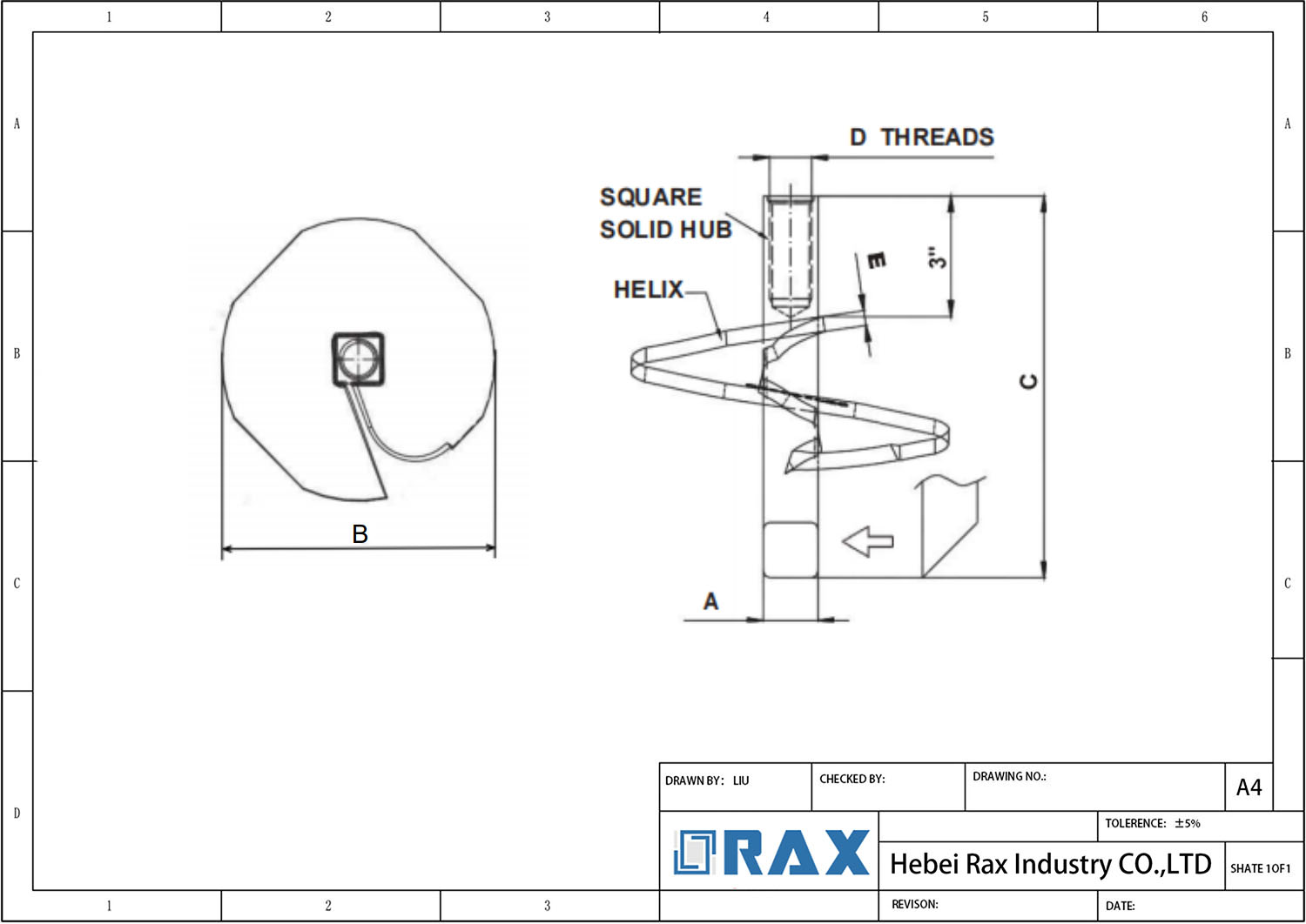
Standard single-shaft no-wrench anchors frequently lack the tensile holding power required for heavy transmission lines and high-wind solar arrays in loose or shallow soil profiles. To resolve this, engineers specify multi-shaft configurations that utilize two or three helices along a continuous, thickened steel rod.
- Dual-Helix Design: Features two welded helix plates spaced along the shaft to significantly increase surface area and friction against the soil.
- Triple-Helix Design: Adds a third anchor point, maximizing holding capacity for extreme dynamic loads without requiring deeper, more difficult-to-drive foundations.
- Robust Eye Rods: Multi-load anchors typically use drop-forged steel rods with reinforced THIMBLEYE® or TRIPLEYE® eyelets, engineered to withstand the immense pulling forces of the guy wires.
These configurations are critical for projects demanding high breaking strength in challenging geotechnical conditions. The dual or triple helix setup distributes the structural load across multiple soil strata, preventing anchor pull-out under severe weather events.
Installation Torque and Depth Requirements
Driving multi-helix anchors requires specialized heavy-duty machinery due to their size and resistance. Installation is typically performed using hole-boring machines equipped with a compatible kelly bar adapter.
- Maximum Torque Limits: For heavy-duty 1-1⁄4″ diameter shafts, installers must monitor torque closely, as these units can safely support an installing torque of up to 2,300 ft.-lbs.
- Extension Rods: When deeper soil layers provide firmer resistance, extension rods are welded or bolted to the top eye section to allow the helix to be driven to the optimal bearing depth.
Large-Diameter No-Wrench Anchors for Utility
In extreme load scenarios, increasing helix diameter is the most efficient engineering solution to maximize pullout resistance without significantly increasing installation depth.
Utility projects involving critical infrastructure, such as heavy-duty transmission dead-ends or large-scale solar foundations, often encounter a fundamental limitation with standard anchors: insufficient surface area. When soil conditions are variable or load requirements exceed 10,000 lbs, standard small-diameter anchors may require impractical depths to achieve holding capacity. Large-diameter no-wrench screw anchors solve this by displacing the same soil volume but at a shallower depth, leveraging the principle that bearing capacity is directly proportional to the area of the helix plate.
Engineering Mechanics of Large-Bore Anchors
The transition to a larger-diameter helix fundamentally alters the load transfer mechanism. Unlike standard anchors which rely primarily on deep soil shear strength, large-diameter units engage a massive volume of soil closer to the surface. This is particularly critical in shallow bedrock scenarios or where the water table limits excavation depth. For B2B buyers, this means a dramatic reduction in installation time and labor costs, as achieving a specific ultimate holding capacity (UHC) does not require drilling to extreme depths.
- Surface Area Multiplier: Increasing the diameter from a standard 6-inch to a larger 8 to 12-inch plate can double or triple the bearing surface area, offering exponential gains in pullout resistance.
- Torque Capacity: These anchors must withstand significantly higher installation torque. therefore, the central shaft is typically manufactured from high-strength steel with a thicker wall profile to prevent torsional failure during the driving process.
- No-Wrench Efficiency: Despite their size, the “no-wrench” design (driving through a forged eye) allows for installation using standard heavy-duty drive bars and machine excavators, eliminating the need for specialized hydraulic torque heads in remote locations.
Structural Integrity and Fabrication Standards
The junction between the helix plate and central shaft represents the highest stress concentration point in high-load anchor configurations. For extreme load applications, hot-forging technology is preferred over traditional casting or simple welding to enhance impact resistance and fatigue life. This method ensures superior durability compared to cast alternatives, which can be brittle under the cyclic loading conditions common in utility grids.
Corrosion protection is non-negotiable for these large-scale investments. Compliance with ISO 1461 hot-dip galvanizing standards ensures a mean coating thickness that typically exceeds 85 microns. This Strong barrier is essential for large-diameter anchors, as the increased surface area of the helix plate exposes more steel to corrosive soil elements. A smooth, bright galvanized finish also facilitates soil displacement during installation, reducing friction and ensuring the anchor achieves the designed torque rating.
Procurement Criteria for High-Load Projects
When sourcing large-diameter no-wrench anchors for bulk utility projects, buyers should prioritize verifiable load testing data over generic catalog claims. Reliable suppliers provide proof of load testing correlating installation torque with holding capacity for specific soil classes. Given the logistical challenges of transporting and deploying larger diameter units, supply chain consistency is vital; batch-to-batch dimensional accuracy ensures that rigging hardware and drive tools fit correctly on site, preventing costly work stoppages.

Best Uses for No-Wrench Screw Anchors
No-Wrench Screw Anchors are primarily deployed in scenarios requiring rapid, heavy-duty anchoring without access to hydraulic machinery, serving as the critical foundation for utility guying, solar racking, and temporary emergency power restoration.
Utility Pole Guying and Distribution Lines
In standard distribution networks, no-wrench anchors provide a reliable termination point for guy wires, mitigating the lateral forces exerted on utility poles. The design centers on an “upset hex” forged into the anchor rod, which allows field crews to install the unit using a simple drive bar and portable manual lever. This eliminates the logistical burden of transporting heavy hydraulic torque motors to residential easements or difficult-to-access roadside locations.
For standard distribution class poles, anchors with a single thimble eye are frequently specified. This configuration allows for direct attachment of guy wires, simplifying the bill of materials by removing the need for separate guy brackets or loops. The immediate tensioning capability post-installation ensures that pole lines can be energized quickly, reducing downtime during maintenance or new construction.
Transmission and High-Tension Applications
When moving beyond distribution to heavier transmission structures or dead-end applications, the load requirements increase significantly. In these scenarios, “Triple Eye” no-wrench anchors are the preferred solution. Unlike standard single-eye variants, the triple eye configuration allows for the attachment of multiple guy strands or facilitates complex rigging geometries where load distribution across several points is necessary to maintain structural integrity.
These anchors are engineered to handle extreme tensile loads often associated with angle poles or dead-end towers. The use of high-strength steel in the helix and shaft ensures that the anchor can withstand the sustained mechanical stress over decades of service. This makes them suitable for critical infrastructure where failure is not an option, specifically in high-voltage transmission corridors where soil conditions necessitate a deep-reaching helix to find stable bearing strata.
Solar Farm Foundations and Renewable Infrastructure
The solar industry requires a ground-mount solution that balances speed of deployment with long-term stability. No-wrench screw anchors have become a standard for fixed-tilt solar racking systems because they function as both a foundation and a ground anchor. The installation process is fast and does not require concrete pouring or curing time, allowing construction schedules to be compressed by weeks.
- Minimal Site Disturbance: Installation leaves a smaller footprint compared to concrete piers, preserving the topsoil and reducing site restoration costs.
- Removability: At the end of the asset’s life, these anchors can be extracted, allowing for site rehabilitation, a critical factor for land leases.
- Immediate Load Capacity: Structures can be mounted and tensioned immediately after installation, accelerating the project timeline.
Emergency Restoration and Temporary Deployment
In disaster recovery scenarios, such as hurricane or storm damage, speed is the primary operational constraint. No-wrench anchors are a staple in utility storm kits. Their lightweight nature allows them to be airlifted or transported in standard pickup trucks to areas where heavy machinery cannot reach due to flooded roads or debris.
Field crews can install these anchors manually to secure temporary poles or stabilize damaged structures until permanent repairs are made. The ability to achieve high holding power quickly without specialized tools makes them indispensable for maintaining grid continuity during critical restoration phases. Furthermore, they are often used in construction sites to support temporary lighting towers or scaffolding, where portability and rapid setup are essential for workflow efficiency.
| Application Scenario | Operational Benefit | Technical Specification | System Compatibility |
|---|---|---|---|
| Large-Scale Utility Projects | Cost-effective solution with accelerated project completion | Ultimate holding strength rated up to 16,000 lbs | Seamless integration with Stay Rod Sets |
| Rapid Deployment Sites | Eliminates need for specialized installation tools | ISO 1461 compliant hot-dip galvanizing exceeding 85 microns | Compatible with Oval Eye and Thimble Eye Bolts |
| Variable Soil Conditions | Enables fast installation without heavy machinery | Ultimate holding strength range of 4,500 to 16,000 lbs | Standardized shaft dimensions for universal hardware compatibility |
Installing Anchors and Setting Torque
Critical Torque Limits During Installation
The installation of no-wrench screw anchors is heavily dependent on precise torque management, which directly dictates the structural integrity of your guy wire or solar foundation. These helical anchors are engineered with specialized turning bars—such as THIMBLEYE® or TRIPLEYE® configurations—to accommodate both manual and machine installation methods. However, the physical limit of the drive rod must never be exceeded to avoid shearing the connection point or stripping the soil structure.
Ensuring Structural Integrity via Proper Setting
Achieving optimal holding strength requires a disciplined approach to the driving process. When utilizing power installation methods via hole-boring machine adapters, operators must maintain a steady rate of penetration. For manual setups, large opening eye rods allow for the use of turning bars, but leverage must be applied carefully to prevent deformation of the forked end. Our engineering teams verify that every anchor meets strict dimensional tolerances before deployment.
- Drive Rod Compatibility: Always match the drive rod diameter and connection mechanism to the specific anchor model (e.g., 4in x 54in Triple Eye vs. Thimble eye) to ensure the torque is transferred cleanly without slippage.
- Extension for Firmer Soil: In high-density soil classes where the initial anchor does not achieve full design depth, engineers should utilize certified extension rods. This allows the anchor to be driven deeper into stable ground without exceeding the torque limits of the primary shaft.
- Hot-Dip Galvanizing Protection: Rax Power utilizes ISO 1461-compliant hot-dip galvanizing with a mean coating thickness exceeding 85 microns. This ensures the structural steel remains corrosion-resistant regardless of the aggressive driving torques applied during initial set-up.
Installation Parameters for Optimal Holding Strength
Holding capacity is strictly a function of vertical depth and soil interaction. Because these units are drop-forged and welded to the helix, they are designed to handle immense axial loads once fully seated. The installation parameter to monitor is not just torque, but the final embedment depth relative to the soil bearing capacity. If the anchor stops prematurely due to hitting an obstruction or reaching torque limits, the resulting pullout resistance will be significantly lower than the rated specifications.
Expert Insight: We do not merely manufacture anchors; we provide a precision-engineered system. Our dedicated QC team ensures that every no-wrench screw anchor undergoes rigorous load testing per industry standards, giving you the confidence that your holding strength ratings are real, not theoretical.
Drive Tools and Rods for Anchors
Executive Summary: Successful deployment of screw anchors requires exact tool matching to the anchor’s shaft geometry and drive configuration to prevent mechanical stripping and ensure the structure achieves its rated pullout capacity.
The mechanical integrity of a guy wire or cross-arm support is only as strong as the connection between the soil and the installation equipment. While modern no-wrench helical anchors are designed for manual torque without heavy hydraulic machinery, selecting the correct drive rod and adapter is a critical engineering decision that directly impacts project efficiency and hardware survivability. Mismatched drive tools lead to wasted labor hours, bent shafts, and severely compromised holding strength.
Essential Drive Rods for Efficient Deployment
No-wrench screw anchors rely on specific top-drive configurations—typically “triple eyes” or heavy-duty thimbles—to accept manual driving hardware. The primary tool used to connect the anchor to the torque source is a heavy-duty drive rod, often referred to in field operations as a Kelly bar or driver extension.
- Material Strength: Standard structural steel drive rods must possess a significantly higher yield strength than the anchor shaft itself. If the drive rod bends before the anchor reaches its torque limit, the force applied to the soil is lost. We utilize hot-forged manufacturing processes for our internal tooling to ensure the metal grain structure remains intact and capable of transmitting high rotational force without deforming.
- Dimensional Matching: Precision is non-negotiable. A drive rod that is too loose within an anchor’s triple eye will create a “hammering” effect during manual rotation, rapidly stripping the metal eyelets and rendering the anchor useless. Conversely, a rod that is excessively tight can damage the galvanizing coating during insertion.
- Length Specifications: Drive rods must be selected based on the expected penetration depth. For deep installations requiring multiple anchor segments or significant soil displacement, extensions must be securely pinned to maintain continuous torque transmission down to the helix blades.
Compatible Tooling for No-Wrench Screw Anchors
The “no-wrench” designation refers to the elimination of heavy hydraulic rotation mechanisms, not the elimination of mechanical effort. These systems are engineered to interface with standard utility industry hand tools. Understanding this compatibility prevents costly field delays.
- Manual Torque Drivers: Most utility pole installations use heavy-duty, manually operated gear-driven wrenches or breaker bars specifically designed for guy line tensioning. The top of the drive rod must feature a square drive or hexagonal head that perfectly matches these standardized manual tools.
- Pin-Connection Systems: To safely transmit torque from the drive rod to the anchor’s triple eye or thimble, high-strength cotter pins or clevis pins are required. Relying solely on friction or lightweight clips can result in catastrophic unhooking under load.
- Solar vs. Utility Adaptation: While solar farm anchors sometimes utilize different top-eye geometries, standard utility-grade no-wrench anchors (such as those utilized by Rax Power) are optimized for standard guy-clamp loads. Confirming the exact diameter of the helix shaft (e.g., 1-inch round vs. 1×6-inch square) is the first step in verifying which torque drivers will physically engage the anchor.
Hardware Selection for Accurate Anchor Placement
Getting the anchor into the ground is only half the battle; keeping it aligned vertically ensures the guy wire pulls strictly downward, maximizing the soil’s bearing capacity. Poor alignment creates lateral shear forces that can pop the anchor out of the ground over time.
- Verticality and Alignment: The chosen drive tool must allow the operator to visually monitor the anchor’s vertical angle. Straight-shaft drive rods facilitate easier plumb-line adjustments compared to bent or kinked extension bars.
- Soil Class Considerations: In highly granular soils, anchors can twist freely if not perfectly vertical. Robust drive tooling allows the operator to apply rapid, controlled bursts of torque, driving the helix into the earth faster and reducing the window for lateral deviation.
- Load Verification: Once installed, the anchor must hold. A dedicated QC protocol, including 100% double-review inspections and rigorous load testing per IEC 120 standards, guarantees that the anchor you install is the same anchor rated for the specified breaking strength. This level of quality assurance ensures that the hardware deployed in the field matches the structural calculations exactly.
Conclusion
Accurate holding capacity predictions require correlating soil class data with specific anchor configurations rather than relying on generic size assumptions.
- Confirm drive tool compatibility with kelly bar adapters for accurate placement.
- Request custom quotes from our engineers for solar farm bulk orders.
- Verify coating thickness on utility pole guy wire anchor rods.
Frequently Asked Questions
What are no-wrench screw anchors?
No-wrench screw anchors, also known as helical screw anchors, are ground anchoring systems designed for installation without specialized heavy machinery. They feature a central shaft with helical flighting that cuts into the soil as the anchor is rotated. This design allows for rapid deployment and immediate load-bearing capacity in various soil conditions.
How do they differ from traditional anchors?
Unlike driven or drilled anchors, screw anchors rely on helical bearing plates to transfer load through skin friction and end-bearing resistance. They require no concrete curing time, allowing for immediate tensioning after installation. This makes them significantly faster to install while providing consistent performance in diverse geological settings.
What is their typical holding strength?
Holding strength varies based on shaft diameter, helix size, and soil density, typically ranging from 4,500 to 16,000 lbs. Higher capacities are achieved by increasing the number of helical plates or using larger diameters. Load testing per standards like IEC 120 ensures each anchor meets its rated structural integrity requirements.
Are they suitable for solar foundations?
Yes, screw anchors are widely used in solar farm foundations due to their quick installation and minimal site disturbance. They provide stable support for racking systems in both residential and commercial solar projects. Their ability to be installed without extensive excavation reduces overall project timelines and costs significantly.
Can they be customized for projects?
Manufacturers often offer OEM/ODM services to tailor shaft lengths, helix configurations, and connection types to specific project needs. Custom mold development allows for precise adaptation to unique structural loads or soil conditions. This flexibility ensures that the anchor system integrates seamlessly with existing pole line hardware or foundation designs.