

Project delays often start at the foundation, especially when soil conditions refuse to cooperate with standard anchoring methods. No wrench screw anchors bypass much of this downtime by accepting installation via a simple turning bar or machine adapter, capable of handling up to 2300 ft.-lbs of torque on a 1-1/4 inch rod. This versatility allows your crews to reach firmer soil depths without specialized tooling, keeping the installation schedule on track.
That reliability is non-negotiable. We examine the helix plate weld integrity and hot-dip galvanizing specs required to ensure these anchors survive decades in corrosive soil without compromising the utility pole guy wire system. You will find the specific load capacities for Class 5 soil and the torque transfer dynamics needed to secure your supply chain against foundation failure.
How They Work: Design and Mechanics
No-wrench screw anchors function as large-scale screws, converting applied rotational torque into linear penetration. The system utilizes a helical blade to slice through soil with minimal disturbance, generating immediate holding capacity through soil displacement rather than expansion or concrete weight.
Torque Transfer Through Drive Rods
The fundamental mechanic of installation relies on efficient torsional energy transfer. Unlike traditional anchors that require a drive chuck or specialized hydraulic head, the “no-wrench” design utilizes the anchor’s own eye—often a Tripleye or Thimbleye configuration—as the drive interface. When a lever bar is inserted into the eye, manual force creates a high-torque rotation. In machine installations, a specialized adapter engages this eye to transfer hydraulic power directly to the rod.
This rotational force travels down the shaft to the helix. The engineering challenge here is not just applying torque, but maintaining structural integrity under shear stress. If the rod material yields or the eye deforms under load, the torque required to penetrate the soil increases exponentially until the rod fails.
At Rax Power, we rely on hot-forging rather than casting for our eye rods. We have consistently observed in our IEC 120 load testing that hot-forged grain structures handle high-torque twisting significantly better than cast alternatives, eliminating the weak point at the critical eye junction.
Helical Blade Penetration Dynamics
The efficiency of the anchor is dictated by the geometry of the helix. The blade acts as an inclined plane wrapped around a central cylinder. As torque is applied, the helix pitch—the distance between blade threads—determines how much linear progress is made per full revolution. A properly engineered pitch allows the anchor to “screw” itself into the earth with a predictable relationship between rotation and depth.
This penetration is not a drilling action; it is a threading action. The leading edge of the helix shears the soil, moving it aside rather than compacting it directly beneath the blade. This mechanism reduces the installation energy required compared to driven piles, which must displace the entire soil column volume by force.
Soil Displacement Mechanics
The holding power is generated entirely through the interaction between the helix and the surrounding soil matrix. As the anchor penetrates, the soil is displaced both downward and radially outward. This action densifies the soil immediately around the helix plate, creating a compacted zone that acts as a physical bearing surface.
- Shear Resistance: When tension is applied to the anchor (pulling up), the helix bears against the compacted soil above it. The anchor resists pull-out by forcing the soil to shear across the cylindrical surface defined by the helix diameter.
- Immediate Loading: Because the capacity relies on soil mechanics (friction and shear) rather than chemical curing (like concrete) or passive pressure (like expansion anchors), the system is often ready for loading immediately upon installation.
This displacement method is particularly sensitive to installation depth. Reaching a stable soil stratum is critical, as the mechanics rely on the “cone of failure” in the soil extending upwards from the helix plate. If the helix is installed in loose topsoil, the failure cone simply slides upward; in stable soil, the cone locks in place, securing the anchor.
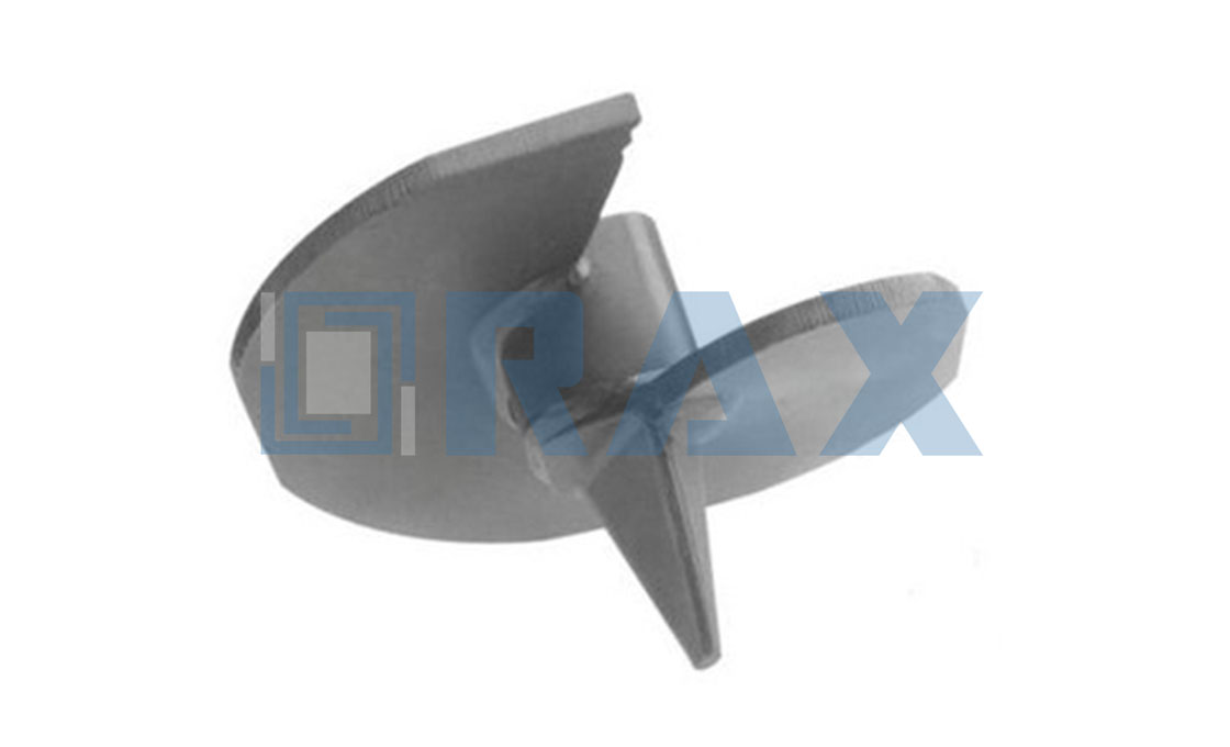
Anatomy of a No Wrench Screw Anchor
Heat-Treated Eye Rod Construction
The foundation of a no-wrench screw anchor’s structural integrity lies in the eye rod, which serves as both the drive shaft and the primary tension point. Unlike standard mild steel rods that are prone to bending under high torque, premium industry specifications mandate the use of drop-forged, heat-treated steel for this component.
This manufacturing process aligns the grain structure of the metal, significantly enhancing tensile strength and resistance to fatigue. In utility applications, particularly where extreme breaking loads are expected, the heat treatment ensures the rod can withstand the immense physical force required to screw the anchor deep into dense soil strata without yielding or shearing.
- Material Durability: High-grade, drop-forged steel is essential to prevent shaft deformation during installation.
- Torque Transmission: The eye rod must be engineered to transfer rotational force from the driving machine directly to the helix plates without mechanical failure.
Helix Plate Weld Integrity
The helix plates—the cutting blades that penetrate the earth—are the most critical load-bearing elements of the anchor. Their connection to the central shaft determines whether the anchor will hold a utility pole securely or suffer catastrophic failure during a storm event.
Industry best practices require the helix plates to be fully welded to the shaft using continuous, high-strength welds rather than spot welding. This creates a rigid, monolithic unit capable of transferring the massive uplift forces from the guy wires directly into the compacted soil. A break in the weld integrity during installation often indicates insufficient heat input or poor material preparation, rendering the anchor unsafe for high-load environments.
- Structural Continuity: Continuous welding prevents the helix plates from detaching when subjected to heavy axial loads.
- Load Transfer: Proper weld fusion ensures that pull-out forces are effectively distributed through the steel shaft into the surrounding ground mass.
Galvanized Coating Thickness Specs
Since these anchors are driven permanently into the ground, they are exposed to moisture, chemical compounds, and corrosive soil conditions. To combat this, manufacturers utilize hot-dip galvanizing, a process where the steel components are submerged in molten zinc.
For heavy-duty utility and solar farm applications, the galvanized coating is not merely cosmetic; it is a critical engineering specification. Industry standards typically require compliance with ASTM A153 (or similar regional equivalents like ISO 1461), dictating a minimum mean coating thickness—often exceeding 85 microns—to guarantee a service life of several decades. This robust zinc layer acts as both a physical barrier and a sacrificial anode, protecting the underlying steel from rust even if the surface is scratched during aggressive installation.
- Corrosion Resistance: Hot-dip galvanizing provides superior, long-lasting protection against underground environmental factors.
- Coating Standards: Adherence to ASTM A153 or ISO 1461 ensures the zinc layer meets the rigorous thickness requirements necessary for permanent infrastructure.
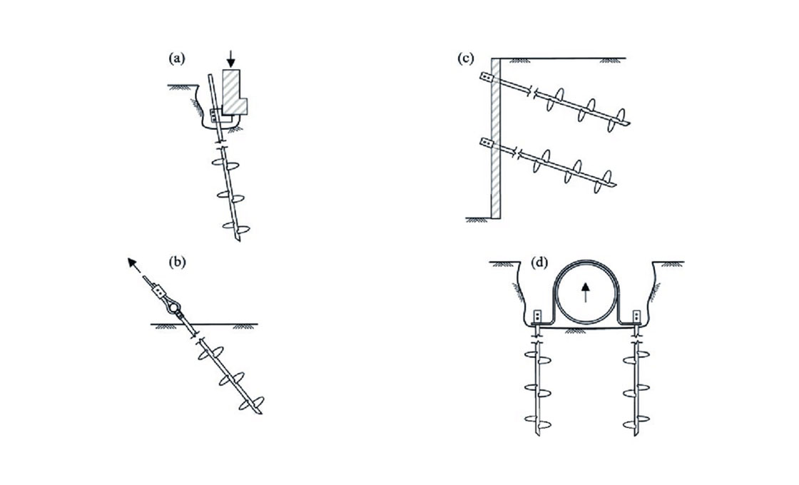
Step-by-Step Installation Guide
Proper torque application and precise alignment are critical for helical screw anchor stability. Ensure the drive rod remains perfectly vertical to prevent soil shearing and guarantee maximum holding capacity.
Manual Installation with Turn Bars
Manual installation via turn bars leverages mechanical advantage to drive anchors in confined utility sites. For small-scale utility projects or areas where heavy machinery cannot access, this is the standard approach. The process relies on the mechanical advantage provided by the THIMBLEYE® or TRIPLEYE® eye rods attached to the anchor head, which serve as the leverage point for manual torque application.
- Preparation: Position the anchor vertically at the designated point. Ensure the eye rod opening is accessible.
- Connection: Insert a standard turning bar into the large opening of the eye rod. Secure it firmly.
- Screwing Process: Apply downward pressure while rotating the bar clockwise. The helix plates will displace the soil and drive the anchor deeper. Maintain a straight trajectory to avoid bending the drive rod.
Mechanized Power Installation with Kelly Bar Adapters
For large-scale solar farm foundations or high-tension utility pole guying systems, mechanized installation is preferred for speed and consistency. This method utilizes hole-boring machines or excavators equipped with hydraulic rotators.
- Adapter Compatibility: Connect a specialized kelly bar adapter or direct drive socket to the machine’s hydraulic rotator. Ensure the adapter matches the specific diameter of the anchor’s drive rod.
- Alignment: Lower the anchor assembly onto the prepared site. Use the machine’s hydraulic legs to apply initial downward thrust before engaging rotation.
- Installation Torque Monitoring: Drive the anchor into the ground until the target depth or torque limit is reached. Monitor hydraulic pressure gauges closely to ensure the load does not exceed the mechanical limits of the components.
Quality Verification and Final Inspection
Regardless of the installation method, the final verification step is non-negotiable for B2B compliance. After reaching the specified depth, disconnect the drive mechanism and inspect the exposed portion of the anchor.
- Visual Check: Verify that the hot-dip galvanized coating per ASTM A153 remains intact. Any significant scratches should be touched up with zinc-rich paint to prevent rust.
- Torque Verification: Record the final installation torque. In geotechnical engineering, higher final torque generally correlates with higher ultimate holding capacity. Use this data for your project’s load capacity documentation.
Load Capacity and Performance Data
Defining Load Capacity Metrics and Soil Classifications
The fundamental engineering challenge in utility pole guying is that “holding capacity” is rarely a fixed physical constant; it is an environmental variable directly correlated to the soil matrix. For B2B buyers managing large-scale solar or transmission projects, understanding how different soil classes affect anchor performance is the single most critical factor in preventing structural failure during wind storms.
In professional engineering standards, holding capacity is generally calculated based on the interface friction between the helical blades and the surrounding soil, combined with the bearing capacity of the bottom-most plate. In dense clay (typically classified as high soil class), the anchor relies heavily on the shear strength of the cohesive material. Conversely, in sandy or loose gravel environments, the anchor must be driven deeper to reach a stratum capable of providing the necessary lateral resistance against guy wire tension.
The Torque-to-Capacity Correlation
Industry best practices utilize installation torque as a real-time proxy for load-bearing capability. During installation, the energy required to screw the anchor into the ground provides an immediate indication of soil density and compaction. Engineers typically apply a specific torque multiplier to estimate the ultimate breaking load before any destructive pull-testing is conducted.
- Low-Torque Scenarios: If the Kelly bar adapter or power installer requires minimal torque to advance the anchor, the soil is likely loose or saturated. This indicates a lower initial holding capacity, necessitating a larger helix diameter or extended depth.
- High-Torque Scenarios: Resistance spike during installation suggests dense soil or rock strata. While this often yields higher holding capacity, installers must remain vigilant for “torque break”—where the drive rod fails or the weld between the helix and the eye rod fractures under excessive stress.
Optimizing Installation Depth and Tension Ratios
Achieving the required tension ratio for a specific utility application depends heavily on the interaction between the anchor geometry and the penetration depth. When specifying no-wrench screw anchors, buyers should evaluate the anchor’s ability to maintain a steady tension ratio even when encountering varying soil profiles within the same trench.
In challenging terrains, extending the anchor depth beyond the standard minimum is often the most cost-effective way to guarantee compliance with safety factors. A longer drive rod allows the helix blades to bypass loose topsoil and anchor firmly into a stable sub-layer, ensuring that the structural integrity of the pole line remains uncompromised regardless of surface weather conditions.
| Feature | Specification | Advantage |
|---|---|---|
| Galvanizing Coating | >85 microns mean thickness (ISO 1461) | Superior corrosion resistance and longevity |
| Structural Integrity | Hot-forged construction | Higher strength and precision vs. traditional casting |
| Load Testing Standard | IEC 120 compliance | Verified dimensional accuracy and safety |
| Dimensional Tolerance | Shaft diameters range from 3/4″ to 1 1/4″, and helix thickness is typically 1/4 inch. | Dimensional tolerances for screw anchors prioritize shaft diameter consistency rather than cross-arm fitment. |
| Quality Assurance | 100% double-inspection by 10-person QC team | Consistent product reliability and SGS verification |
No Wrench vs. Traditional Anchors
Eliminating Mobilization Overhead
The primary bottleneck for traditional screw anchors is the requirement for high-torque hydraulic drive heads. These heavy machines are expensive to rent, consume significant fuel, and take hours to mobilize on-site. For a standard utility pull or a small-scale solar racking job, renting this machinery often costs more than the anchor hardware itself. The cost-to-benefit ratio collapses when the anchoring demand is low.
No-wrench screw anchors resolve this financial inefficiency by decoupling installation from specialized machinery. A simple manual turning bar fits directly into the eye rod’s large opening, allowing field crews to install the anchors using human power alone. This transforms a high-overhead mechanical operation into a light, fast manual task.
Operational Flexibility and Tooling
- Manual Efficiency: Hand installation using a turning bar allows for precise depth control and reduces site noise and vibration, which is critical in populated areas or sensitive ecological zones.
- Mechanical Compatibility: When soil density increases and hand torque becomes insufficient, the same anchor can be installed using a machine adapter compatible with standard hole-boring equipment or excavators.
- Torque Management: Standard no-wrench anchors are engineered to safely withstand up to 2,300 ft.-lbs. of installing torque, providing ample strength for deep penetration without risking structural failure during installation.
Cost Analysis: Upfront vs. Hidden Expenses
For traditional anchors, the budget must account for heavy machinery rental, fuel consumption, and the need for experienced operators to run high-torque drills. No-wrench anchors shift the cost structure entirely. By utilizing basic hand tools, contractors eliminate daily rental fees and reduce labor hours by up to 70% on standard guy-wire installations.
Drop-forged steel welded directly to the helix prevents shear failure under high manual turning loads. This robust construction ensures the joint resists the concentrated leverage of a manual turning bar, maintaining structural integrity during installation.
For dense soils where hand-torque limits are reached, extendable rods allow crews to reach deeper, firmer strata without switching out the anchor hardware, maintaining a single procurement line item.

Galvanizing Quality and Durability
Galvanizing serves as critical corrosion insurance, requiring ISO 1461 compliance and >85-micron thickness.
The Critical Importance of Hot-Dip Galvanizing Standards
In the utility and solar sectors, pole line hardware and earth anchors are constantly exposed to aggressive soil chemistry, moisture, and atmospheric pollutants. A substandard galvanizing layer is the leading cause of premature structural failure, leading to expensive maintenance shutdowns and safety hazards. To mitigate these risks, industry professionals strictly adhere to the ISO 1461 standard for hot-dip galvanized coatings on iron and steel articles.
This standard specifies not just the process but the physical properties of the coating. A quality galvanizing operation creates a metallurgical bond between the zinc and the steel, forming zinc-iron alloy layers that are harder than the base metal itself. This is distinct from electroplating or mechanical plating, which merely sits on the surface and can flake off during the high-torque installation of screw anchors or during transport.
Coating Thickness: The 85-Micron Benchmark
The most critical metric for durability is coating thickness, measured in microns (µm). While minimal requirements exist, high-performance infrastructure demands a strong margin of safety. For heavy-duty applications, the industry benchmark for a mean coating thickness is 85 microns. This level of coverage ensures that even if minor surface abrasions occur during handling or installation, sufficient zinc remains to provide sacrificial cathodic protection to the underlying steel.
Buyers must be wary of “thin-dip” alternatives that scrape easily. When specifying pole line hardware or anchors, insisting on a mean thickness exceeding 85 microns significantly extends the service life of the asset, often matching the 50+ year design life of the utility poles or solar racking systems they support.
Visual Quality and Surface Finish
While thickness is quantifiable, the visual appearance of the galvanizing serves as an immediate “bullshit detector” for quality control. A high-quality finish should be smooth, bright, and continuous. Dull, grey, or excessively rough surfaces often indicate poor bath temperature control or inadequate fluxing, which can hide underlying coating weaknesses.
additionally, the presence of zinc drips, runs, or ash inclusions is not just aesthetic; these irregularities can interfere with the fitment of nuts on bolts or the proper seating of guy clamps. Precision manufacturing requires that the galvanizing process enhances the hardware without compromising dimensional tolerances.
Always require third-party verification for coating thickness. Reputable manufacturers conduct in-house gauge testing per IEC 120 standards and have their batches verified by independent entities like SGS. Never rely on a supplier’s self-declaration alone for critical load-bearing infrastructure.
Technical Specifications for Compliance
When auditing a supplier for galvanizing quality, the following technical specifications should serve as the baseline for approval:
- Standard Compliance: Adherence to ISO 1461 (or ASTM A123 for structural steel shapes).
- Mean Coating Thickness: Minimum requirement of 85 microns, ensuring long-term corrosion resistance.
- Surface Appearance: Smooth, bright finish free from flux deposits, ash inclusions, or uncoated areas.
- Adhesion: Coating must be firmly adherent; it should not flake or peel when subjected to standard cutting or deformation tests.
- Verification: Products must be certified via SGS testing or equivalent third-party inspection reports.
Best Applications for These Anchors
Utility Pole Guying Systems
Utility pole guying systems require anchors capable of withstanding high lateral tension and dynamic uplift forces, particularly in regions prone to heavy ice loading or strong winds. Unlike traditional concrete ballast blocks which are difficult to install and transport, our helical screw anchors provide immediate structural integrity by transferring the load deep into stable soil layers.
- High Tensile Resistance: The helical design allows for rapid installation while delivering superior holding capacity against the pull-out forces common in guyed line configurations.
- Adaptability: Essential for remote or rugged terrain where pouring concrete is logistically unfeasible or environmentally restricted.
Solar Racking Foundation Support
In solar farm construction, foundation stability is critical for maintaining panel alignment and preventing shading issues over time. Helical screw anchors serve as a robust foundation support system, offering immediate load-bearing capability that allows for faster project deployment compared to waiting for concrete curing.
- Speed of Deployment: Mechanical installation eliminates weather-related delays associated with concrete foundations.
- Reusability: These anchors can be unscrewed and relocated at the end of a project’s life, reducing waste and cost compared to permanent concrete footings.
Our hot-dip galvanized process ensures corrosion resistance exceeding 85 microns in thickness, providing decades of protection against soil moisture and chemical exposure, which is vital for the longevity of solar infrastructure.
Telecommunications Tower Grounding
For telecommunications towers, grounding systems are essential for protecting sensitive equipment from power surges and ensuring personnel safety. Our helical screw anchors are specifically designed to function as effective ground electrodes, providing a large surface area contact with the earth to minimize grounding resistance.
- Low Ground Resistance: The helical plates maximize soil contact, significantly lowering electrical resistance compared to single-rod driven systems.
- Corrosion Protection: The robust galvanization prevents rust buildup at the metal-soil interface, which is a common cause of increased resistance in traditional grounding rods over time.
Is This Anchor Right for Your Project?
Soil Type Compatibility Analysis
Your anchor selection is dictated by the soil profile, not just the line tension requirements. In soft, sandy, or loose cohesive soils, helical anchors (both round and square shaft profiles) provide superior displacement mechanics, allowing the helix plates to lock into denser strata without pre-drilling. For rocky or highly variable terrain, expanding or cross-plate anchors offer better friction-based resistance.
We have found that specifying the correct helix geometry for your specific soil class—such as Class 5 loads in helical screw applications—prevents catastrophic settlement. If you are navigating complex regional tender requirements, like those in Southeast Asia, we utilize OEM/ODM capabilities to customize the shaft diameter and helix pitch to match the exact geotechnical survey data provided by your local contractors.
Ultimate Holding Capacity Metrics
Holding capacity is strictly a function of installation torque and soil density, but the structural integrity of the anchor determines the maximum limit before failure. Our hot-forged no-wrench screw anchors are engineered to handle extreme axial loads without bending or shearing at the weld points—a common failure mode in traditional cast competitors.
- Hot-Forged Integrity: Unlike casting, our hot-forging process aligns the metal grain structure, providing significantly higher yield strength for the eye rod and helix connection.
- Torque Correlation: We adhere to rigorous IEC 120 load testing standards. Our engineers consistently see that when installed to proper torque specs, our anchors reliably achieve the ultimate holding capacity calculated during the design phase.
- Galvanizing Protection: Long-term capacity relies on material preservation. Our ISO 1461 compliant hot-dip galvanizing ensures a mean coating thickness exceeding 85 microns, preventing corrosion from reducing the cross-sectional area over decades of service.
Installation Depth and Tension Ratio
Achieving the required safety factor (tension ratio) depends entirely on driving the anchor to its designated “refusal depth” in competent soil. No-wrench screw anchors can be installed to greater depths using extension rods to bypass loose topsoil and reach firmer layers, ensuring the tension ratio meets utility standards even in poor surface conditions.
For high-tension projects in South American utilities or Russian extreme environments, we verify that the installed depth allows for an adequate margin of safety. Our double-review QC protocol ensures that every delivered anchor is dimensionally accurate to within strict tolerances, meaning field teams spend less time adjusting for manufacturing defects and more time achieving the necessary embedment depth for reliable line support.
Conclusion
Selecting the right anchor means understanding how torque transfer translates directly into holding capacity for specific soil classes. You cannot overlook the heat-treated eye rod construction or the galvanizing specs if you want long-term corrosion resistance in solar or utility projects. It comes down to matching the shaft diameter and helix configuration to your specific ground conditions. There is no universal fit here, so precise calculations matter.
- Verify your soil class data before choosing a helix configuration.
- Check the installation torque against the manufacturer’s capacity charts.
- Contact our engineering team to review your site plans and soil reports. We help validate torque ratings and extension rod requirements early in your design phase to ensure safety compliance.
Frequently Asked Questions
What are no wrench screw anchors?
No wrench screw anchors are helical ground anchors designed for installation using standard rotary tools without specialized gripping equipment. They feature a threaded shaft and flighting that screws directly into the soil, providing immediate holding power. This design eliminates the need for complex mechanical wedges or tensioning devices during the initial setting phase.
What installation tools are required?
Installation typically requires a hydraulic torque motor, a manual crank handle, or a rotary drill with a specific attachment. The key is applying steady rotational force to drive the anchor into the ground. Specialized wrenches are not needed, making field deployment faster and less labor-intensive.
Are they suitable for seismic zones?
Yes, their flexible yet strong threaded design allows them to absorb dynamic loads effectively. The helical shape distributes stress along the shaft rather than at a single point. This makes them resilient against ground movement and vibration common in earthquake-prone regions.
Can they be removed after use?
One major advantage is their reversibility; they can be unscrewed from the ground when no longer needed. This allows for site restoration and potential reuse of the hardware. It is particularly useful for temporary structures or solar installations requiring periodic maintenance.
How does Raxpower ensure quality?
Raxpower employs rigorous hot-dip galvanizing compliant with ISO 1461 standards to prevent environmental degradation. Their products undergo SGS verification and IEC 120 load testing to guarantee structural integrity. A dedicated QC team performs double-inspections to ensure every unit meets precise dimensional tolerances before shipment.