
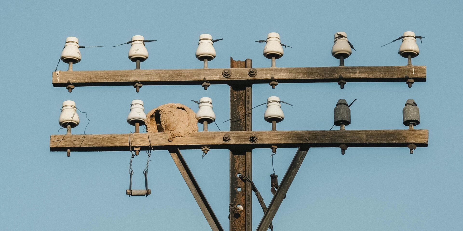
Defining the correct specifications for 132 kV post insulators requires exacting attention to dimensional detail. Standard composite units for this voltage class typically require a mounting height of 1245±20mm while maintaining a minimum creepage distance of 3200mm to handle pollution levels effectively. Getting these numbers right on paper doesn’t guarantee they arrive on site that way. At Rax Power, our internal quality data shows that aggressive tolerance verification is the only reliable way to prevent mounting mismatches. This guide clarifies the critical interface tolerances defined by IEC and ANSI standards, specifically focusing on the dimensional stability differences between ceramic and composite cores.
You need to know where a manufacturer can save cost without risking failure and where they absolutely cannot. We analyze the specific testing protocols that verify long-term dimensional drift under thermal cycling and mechanical load. By understanding these nuances, you protect your project timeline from the re-work delays caused by non-fitting hardware.
IEC and ANSI Dimensional Standards Compliance
The most expensive mistake in global procurement is assuming IEC and ANSI standards are interchangeable translations rather than distinct engineering philosophies.
Normative Frameworks for 132 kV Systems
Navigating 132 kV insulator specifications requires understanding that IEC and ANSI operate on fundamentally different documentation architectures. The IEC approach is modular: you must reference the horizontal test standard IEC 60383 for testing methods, then cross-reference specific product standards like IEC 60720 (line post) or IEC 60168 (station post) for dimensions and ratings. ANSI takes a bundled approach via the C29 series—specifically ANSI C29.7 for ceramic line posts—where product definitions, tests, and dimensions are consolidated into a single document.
This structural difference creates a compliance risk during tender evaluation. If an EPC firm specifies ‘IEC 60383 compliance’ without citing the specific product standard for the interface dimensions, manufacturers lack a complete normative reference to verify geometric fit. For 132 kV systems specifically, ensure the specification explicitly links the test method (IEC 60383) with the product standard (IEC 60168 or 61952) and the environmental selection guide IEC 60815 to avoid ambiguous technical deliverables.
Dimensional Tolerances: Metric Precision vs. Legacy Fit
While the data tables provide the nominal values, the engineering reality lies in the tolerance philosophy. ANSI standards often carry the legacy of imperial measurements, resulting in interface tolerances that are historically driven by specific utility hardware templates. IEC tolerances, being strictly metric, can sometimes appear broader or more generalized, placing the burden of ‘fit’ verification on the manufacturer’s adherence to the product standard rather than a specific gauge tool.
Pollution Classes: The Interpretation Gap
Creepage distance is defined mathematically, but the Pollution Class (I to IV) assigned to a site is a subjective engineering judgment. IEC 60815 provides the selection methodology, but a ‘Heavy Pollution’ classification in a coastal region with salt fog differs physically from an industrial zone with cement dust. The ‘gap’ in standard interpretation arises here: two engineers can look at the same site, validly apply IEC 60815, and arrive at different creepage requirements based on their risk appetite for cleaning schedules.
This ambiguity directly impacts the insulator’s overall geometry and diameter. Over-specifying the pollution class inflates the cost and size unnecessarily; under-specifying it invites flashover events. To bridge this gap, do not rely solely on the standard class label. Instead, specify the minimum Specific Creepage Distance (mm/kV) required in the technical schedule. This removes the subjectivity of the class definition and locks the manufacturer into a precise dimensional target.
| Component Category | IEC Standard Scope | ANSI / NEMA Standard Scope | Compliance Mapping | Critical Note |
|---|---|---|---|---|
| Standard Structure | Layered System: Horizontal test standards (IEC 60383) + Specific product standards (IEC 60168, 61952) | Bundled System: Product type, ratings, and tests in single type-specific documents (C29.x series) | Cross-region procurement requires mapping both axes, not just translating part numbers | IEC splits product definition from test method; ANSI bundles them into one document set |
| Ceramic Line Post | IEC 60720 (Product) + IEC 60383-2 (Test Reference) | ANSI C29.7 (High-Voltage Line Post) | IEC 60720 maps to C29.7 for ceramic line post dimensional & mechanical specs | Verify specific edition cited in project specification as mapping is inferred for EPC bids |
| Ceramic Station Post | IEC 60168 (Contains both product specs and test references) | ANSI C29.9 (Station Post) | IEC 60168 is the direct functional equivalent to C29.9 for substation posts | IEC 60168 is self-contained for testing, unlike other IEC product families |
| Composite Line Post | IEC 61952 | ANSI C29.17 / C29.18 (Composite Line Post) | Direct mapping between IEC 61952 and ANSI C29.17/18 family | Critical for specifying polymer hardware in different grid infrastructures |
| Composite Station Post | IEC 62231 | ANSI C29.19 (Station Post Composite) | IEC 62231 aligns with C29.19 for composite station insulation | Ensure creepage requirements match local pollution classes (IEC 60815 vs IEEE) |
| Creepage & Pollution | IEC 60815-1/-2/-3 (Selection for polluted environments) | IEEE Std 4 / IEEE 1313 (Referenced within C29) | IEC provides a dedicated standard series; ANSI references IEEE for methodology | Creepage distance calculation methods vary significantly between families |
| Voltage Test Criteria | Withstand Values (Power-frequency wet, Lightning impulse) | Flashover Values (Critical Impulse Flashover – CFO) | Not one-to-one; CFO (50% flashover) != Withstand (Guaranteed floor) | A unit passing ANSI CFO at X kV may fail IEC Withstand at X kV |
| Mechanical Rating | SML (Specified Mechanical Load) / SFL (Specified Failing Load) | M&E (Mechanical and Electrical) Strength | M&E rates load at 1 min under combined voltage; SML/SFL focuses on load capacity | Load duration definitions differ; verify test durations match project specs |

Nominal Height & Core Diameter
Nominal height and core diameter are the non-negotiable baselines for 132 kV structural integrity. Exceeding standard tolerances by even millimeters compromises safety clearance and mechanical load ratings.
Core Diameter: The Backbone of Mechanical Integrity
Mechanical performance in 132 kV solid-core post insulators hinges directly on the core diameter. For a unit requiring a standard 12.5 kN bending strength, the core diameter is the primary determinant of performance. It is not a variable to be trimmed for cost savings; it is a fixed non-negotiable. A deviation in core diameter directly alters the section modulus, meaning a reduction of just a few millimeters can significantly lower the unit’s ability to withstand cantilever loads and torsional stress during high-wind events. Unlike competitors who may rely on casting—a process prone to porosity and dimensional inconsistency—we utilize hot-forging technology. This ensures the internal structure is dense and the diameter remains uniform from the base to the top cap, eliminating the weak points found in lower-quality alternatives.
Nominal Height and Thermal Compensation
Nominal height defines the critical creepage distance and phase-to-ground clearance. However, buyers often fail to account for thermal drift when specifying height. Ceramic materials have a low coefficient of thermal expansion, but composite insulators can exhibit creep or expansion over time, especially in the extreme temperature variances seen in markets like Russia or Southeast Asia. To prevent installation failures, the specified nominal height must account for the galvanizing thickness on end fittings. We apply a hot-dip galvanizing process compliant with ISO 1461, ensuring a mean coating thickness exceeding 85 microns. While this adds superior corrosion resistance, it adds physical material dimensions. Our engineering team factors this coating depth into the initial design phase, ensuring the final assembled unit meets the exact electrical clearance requirements without the need for field shimming.
Manufacturing Control: The Rax Power Standard
Achieving theoretical dimensions on a CAD drawing is easy; holding them in mass production is where the supply chain often fails. We apply the same rigorous tolerance standards used in our steel cross arms—where we maintain a strict 1mm tolerance—to our insulator lines. Our automated machinery guarantees that the first unit and the thousandth unit are dimensionally identical.
- Double-Review QC Protocol: Every unit undergoes two distinct dimensional inspections before packaging. A dedicated 10-person QC team monitors critical interfaces to ensure mounting holes align perfectly with substation structures.
- In-House Gauge Testing: We conduct rigorous gauge testing per IEC 120 standards. This verifies that the core diameter and spacing remain within strict safety margins, even under thermal load simulation.
- SGS Verification: Our dimensional control protocols are not internal secrets but verified standards. All processes and products are SGS tested and verified, providing the traceability required for high-tier utility tenders in South America and Europe.
Creepage Distance & Shed Spacing
Effective pollution performance relies not just on total creepage distance, but on optimized shed geometry that maximizes self-cleaning while maintaining mechanical integrity.
The Engineering Logic Behind Shed Spacing
Specifying creepage distance is more than just calculating a total length; it requires precise geometry to ensure the insulator can shed contaminants effectively. In high-pollution environments, such as coastal areas or industrial zones, a simple increase in length is insufficient if the shed spacing allows for pollution bridging under wet conditions. A common pain point for procurement teams is receiving insulators that technically meet the minimum millimeter ratings but fail in the field due to poor aerodynamic profiles that encourage dirt accumulation on the lower surfaces.
Optimizing Geometry for Severe Environments
To counteract flashovers, the ratio between shed spacing and projection becomes a critical factor. An open aerodynamic profile is essential to ensure natural wind cleaning and prevent the formation of continuous conductive paths. We have observed that inconsistent molding in manual production often leads to uneven spacing, creating “dead zones” where pollution builds up. To eliminate this risk, we utilize automated molding systems that guarantee uniform geometry across every batch. This ensures that the self-cleaning capabilities designed in the lab translate directly to field performance.
Verification and Quality Control
Visual inspection alone is insufficient to validate complex profiles. At our facility, rigorous dimensional gauge testing is applied to every production run to verify that the alternating sheds meet the strict specifications required for heavy pollution standards. Our 10-person QC team performs a double-review process, rejecting any unit where the shed spacing deviates from the design parameters. This strict adherence to geometric consistency is why our insulators maintain hydrophobicity transfer capabilities and withstand the specific demands of utility tenders in regions like South America and Southeast Asia.
| Parameter | 132 kV Industry Standard | Rax Power Quality Assurance | Key Benefit |
|---|---|---|---|
| Specific Creepage Distance | ≥ 31 mm/kV (Total ≥ 4495 mm) | Design exceeds Class IV pollution standards; SGS verified | Prevents flashovers in coastal/saline environments |
| Shed Profile & Ratio | Open aerodynamic alternating sheds; S/P ratio ≥ 1 | Automated precision molding ensures consistent geometry | Enhances self-cleaning and hydrophobicity transfer |
| Dry Arcing Distance | Minimum 1.5 m | In-house testing per IEC 120 standards | Guarantees reliability during switching surges |
| Connecting Length | 1.48 ± 0.02 m | 100% double-review process by dedicated QC team | Seamless fit with mounting hardware and cross-arms |
| Insulation Length | Minimum 1.2 m | Rigorous dimensional gauge testing | Ensures safe isolation of live components |
End Fitting Interface Tolerances
To prevent assembly blocking, interface dimensions must account for the mean zinc coating thickness exceeding 85 microns required by ISO 1461.
The most frequent failure mode in pole line hardware assembly is not material failure; it is the inability to assemble components on site due to tolerance stack-up. B2B buyers often face a scenario where standard U-bolts will not pass through pole band holes, or clevis pins bind in insulator caps. This typically happens when manufacturers drill to the nominal steel size and ignore the dimensional build-up added by the galvanizing layer. This oversight creates immediate installation delays, forcing crews to ream holes or use hammers—actions that compromise the integrity of the corrosion protection.
At our facility, we treat galvanizing as a critical variable in our tolerance equation, not a secondary coating process. We strictly adhere to ISO 1461 hot-dip galvanizing standards, which results in a mean coating thickness exceeding 85 microns. To ensure 100% compatibility, our automated production lines pre-calibrate drilling dimensions to account for this specific zinc thickness. We apply a “reverse tolerance” strategy: if the final assembly requires a 16mm bolt, we drill the raw material significantly larger so that after the 85-micron coating is applied, the clearance is perfect. This ensures that when your installation crew arrives, the hardware slips together without force or modification.
Technical Tolerance Protocols
- Coating Compensation: All drilling and boring dimensions are offset to accommodate the mean zinc thickness of over 85 microns, ensuring post-galvanized interface accuracy.
- Hot-Forging Consistency: By employing hot-forging rather than casting for critical interfaces, we minimize shrinkage and warping, delivering superior dimensional stability compared to traditional sand-cast methods.
How do you verify the interface dimensions match insulator standards?
We do not rely solely on calipers. Our in-house QC team performs physical gauge testing per IEC 120 standards on every batch. This verifies that the curvature, ball/socket dimensions, and pin clearances will mechanically lock with standard insulators before the goods leave the factory floor.
Cantilever Strength vs. Height
Increasing mounting height linearly amplifies bending stress at the base, requiring a proportional increase in specified Cantilever Strength to maintain safety margins.
The Physics of Leverage on 132 kV Systems
Leverage mechanics dictate that increased mounting height amplifies the moment arm at the base. Consequently, even standard wind or conductor loads generate significantly higher bending stresses at the root. For 132 kV solid-core post insulators, this is not merely a theoretical concern but a critical safety factor. While standard specifications often list a nominal bending strength of 12.5 kN, real-world applications involving taller mounting configurations demand engineers calculate the specific moment load to verify that this rating provides a sufficient safety factor.
Material Consistency Under Stress
Height-induced stress exposes inconsistencies in manufacturing that might otherwise remain dormant at lower elevations. A taller insulator acts as a longer lever, magnifying any microscopic voids or uneven cementing within the end fittings. We address this by utilizing advanced hot-forging technology for our metal components rather than traditional casting. This method ensures the grain structure of the steel is continuous and aligned, offering superior toughness to handle the amplified leverage forces found in elevated 132 kV installations. Furthermore, our strict 1mm dimensional tolerance on steel cross arms ensures that the insulator is seated perfectly flat, preventing point-loading stresses that could compromise a taller unit.
Verification Protocols for High-Stress Applications
To guarantee performance across all specified heights, we implement a double-review process that goes beyond standard sampling. Every unit undergoes rigorous in-house load testing and gauge testing per IEC 120 standards before packaging. This protocol is crucial because a taller insulator failing under cantilever load poses a severe risk to grid stability.
- Rigorous destruction testing confirms that theoretical ratings align with physical performance limits. We validate the 12.5 kN bending rating and 3 kNm torsional strength through physical destruction tests on sample batches.
- End Fitting Security: Our automated crimping and assembly processes guarantee the bond between the porcelain core and metal flanges can withstand the increased leverage without creeping or loosening over time.
- SGS Certification: All processes are verified by SGS, providing third-party validation that our cantilever strength claims are accurate and reliable for high-stakes environments.

Mounting Center-to-Center Spacing
In 132 kV transmission infrastructure, the mounting center-to-center spacing—the precise distance between the bolt holes on the support structure—is rarely given the attention it deserves during the procurement phase. Yet, this dimension is the single most critical factor in determining whether a project proceeds smoothly or stalls due to fitment issues. A deviation of just a few millimeters might seem negligible in a warehouse, but on a tensioned pole line, it forces installation crews to compromise the hardware’s integrity through field modifications. Buyers often settle for “standard” spacing without realizing that “standard” varies wildly between regions and manufacturers, creating a logistical nightmare when mixing and matching components from different suppliers.
Orientation Sensitivity and Load Distribution
The impact of spacing tolerance is heavily dependent on the mounting orientation. For horizontal line post applications, which are common in 132 kV systems, the insulator acts as a cantilever beam. If the center-to-center spacing on the cross arm does not match the insulator’s base dimensions precisely, the mounting hardware is subjected to uneven shear stress. This misalignment creates a bending moment at the connection point that the hardware was not designed to withstand. While vertical mounting offers some forgiveness through gravity, horizontal configurations demand absolute precision. In our experience, the majority of hardware fatigue failures in horizontal installations can be traced back to initial spacing deviations exceeding 2mm.
Eliminating the “Force-Fit” Risk with Automation
This is where we differentiate our manufacturing approach from the general market. We identified that inconsistent spacing in steel cross arms and pole brackets was a primary pain point for our B2B partners, leading to increased installation times and higher return rates. To solve this, we implemented fully automated production lines for our steel cross arms, ensuring a strict 1mm tolerance on all center-to-center dimensions. Unlike traditional manual fabrication methods, which are prone to human error and cumulative drift, our automated systems guarantee that every bracket leaving our factory matches the nominal drawing exactly.
- Zero-Field Modification: Our 1mm tolerance ensures that insulators bolt directly onto our cross arms without the need for shims, washers, or dangerous on-site drilling.
- Protected Structural Integrity: Exact spacing prevents point-loading on insulator end fittings, preserving the cement and preventing the micro-cracks that lead to premature failure.
- Bulk Consistency: For large-scale utility projects, our automated process guarantees that the 1,000th cross arm is identical to the first, eliminating the variability that plagues cast or loosely fabricated alternatives.
Installation Clearance & Spacing Tables
Clearance is the invisible insurance policy of the grid. Calculating for dry air is easy; calculating for dynamic conductor swing, wind loads, and maintenance tool arcs is where engineering precision separates a compliant line from a failing one.
Phase-to-Phase and Phase-to-Ground Clearance Values
For 132 kV systems, statutory minimum clearances are non-negotiable safety baselines defined to prevent flashover under power frequency and switching surge conditions. While specific values vary slightly by regional code (IEC vs ANSI), industry standard baselines for 132 kV infrastructure typically require a minimum phase-to-ground distance of approximately 1,200 mm and a phase-to-phase spacing of at least 1,500 mm to account for overvoltage stress.
Minimum Safety Distances for Live-Line Maintenance
Beyond static clearance, engineers must design for the Minimum Approach Distance (MAD) required for hot-stick or bare-hand maintenance. For 132 kV lines, the MAD is typically calculated around 0.9 to 1.0 meters from the energized conductor. However, this is a theoretical minimum for the worker’s body; the structure must accommodate the additional reach of conductive tools (hot sticks), which can extend the required zone to 1.5 meters or more.
Impact of Mounting Orientation on Clearance Requirements
Mounting orientation fundamentally alters clearance physics. Vertical mounting is geometrically stable, but horizontal mounting (line post) introduces dynamic variables. When installed horizontally, the insulator acts as a cantilever beam. Under maximum wind load or ice weight, the conductor deflects downward and swings laterally. This ‘swing angle’ eats into your phase-to-ground and phase-to-phase margins.
This mechanical deflection means the initial electrical clearance must be oversized to preserve the safety gap at maximum deflection. In our production facility, we mitigate this risk at the hardware level. Because our steel cross arms are manufactured with an automated tolerance of just 1mm, we eliminate the ‘wobble’ or play often found in loosely fitted assemblies. This precision ensures that the initial positioning is millimeter-perfect, allowing you to reserve your entire safety margin for environmental factors rather than installation error.
Quality Verification & Dimensional Drift
Passing the initial inspection guarantees today’s fit. Validating geometric stability over thermal cycles guarantees the fit 30 years from now.
Lifecycle Stability Prediction for Thermal Cycling
Standard ceramic cores exhibit minimal thermal expansion, typically under 6 x 10⁻⁶/K, ensuring geometric stability across temperature fluctuations. The critical risk lies in the polymer interfaces of end fittings and the cementitious grout used to bond the core to the metal. Under repetitive thermal cycling—ranging from -40°C in northern climates to +80°C in direct sunlight—differential expansion rates can induce micro-cracking at the interface. This “dimensional drift” is often imperceptible during a standard 48-hour test run but accumulates over a 20-year service life, potentially compromising the mechanical cantilever strength.
We have observed through our long-term supply relationships in Russia that units subjected to extreme, rapid temperature shifts require a specific cement formulation. Standard mortar mixtures often degrade under these freeze-thaw cycles. We account for this by using sulfur cement or specialized epoxy compounds for high-voltage units destined for volatile environments, ensuring the interface remains rigid regardless of thermal stress.
Advanced Measurement Techniques for Internal Tolerances
Standard calipers verify external dimensions, yet they fail to detect critical internal tolerance stack-ups. The interface between the insulator core and the end fitting relies on precise internal clearances to maintain structural integrity. To verify this, advanced measurement must move beyond basic length checks.
- IEC 120 Gauge Testing: This is the non-negotiable standard for verifying interface dimensions. We utilize precision “Go/No-Go” gauges to check the ball, socket, and tongue dimensions of every end fitting. This ensures mechanical interchangeability and correct fit-up with hardware during assembly.
- Coordinate Measuring Machines (CMM): For custom ODM projects, we deploy CMMs to map the complex geometry of clevis and tongue interfaces, identifying deviations as small as 0.02mm that traditional calipers would miss.
- Ultrasonic Thickness Testing: This verifies the uniformity of the porcelain wall thickness, detecting eccentricity that could lead to weak points under high mechanical load.
Our quality protocol mandates a 100% double-review process. A dedicated 10-person QC team inspects every unit immediately after galvanizing and again before packaging. This redundancy catches the 0.5% of units that might pass a single automated visual scan but fail a tactile gauge test.
Temperature Compensation Effects on Interface Dimensions
The interface dimensions of the end fitting are not static; they fluctuate with ambient temperature. Steel end fittings have a higher coefficient of thermal expansion than the ceramic core. During installation in high-temperature environments, the metal expands, potentially altering the engagement depth of the ball and socket or the pin-hole diameter.
Conclusion
Don’t just chase the lowest unit price. If the mounting spacing is off by even a few millimeters, your field crew loses hours adjusting brackets. Stick to IEC 60383 tolerances rigorously, especially for creepage distance in polluted areas. Ceramic offers better long-term dimensional stability than composites for rigid 132 kV bus supports, so choose material based on thermal cycling expectations. Precision now prevents expensive downtime later.
We treat dimension verification as a critical ROI factor, not just a paperwork step. Our 10-person QC team performs a rigorous double-review on every batch to guarantee those IEC tolerances are dead-on before shipping. Send us your specific mounting drawings or technical specs. We’ll run a free compatibility check to ensure the end fittings align perfectly with your existing hardware structure.
Frequently Asked Questions
What are critical creepage and spacing dimensions?
Critical dimensions include creepage distance, which must be sufficient to prevent flashovers under pollution conditions, and core diameter for mechanical strength. Engineers must also verify the dry arcing distance to ensure electrical safety clearances are met. These measurements must align with IEC standards to guarantee reliable performance in 132 kV transmission.
What are standard dimensional tolerances?
Standard tolerances for high-voltage insulators are typically governed by IEC specifications to ensure universal fitment and safety. Tighter tolerances are crucial for connecting hardware, as even minor deviations can cause assembly stress or failure. Manufacturers often implement automated systems to maintain consistency across large production volumes.
Ceramic vs Composite Dimensional Stability?
Ceramic insulators maintain rigid dimensional stability over decades, making them highly predictable under heavy mechanical loads and compression. Composite alternatives offer advantages in weight and vandalism resistance but require strict monitoring for creep and long-term material degradation. Selection should be based on specific environmental conditions and the mechanical stress dynamics of the 132 kV line.
How does environment affect dimensions?
Environmental factors such as extreme thermal cycling can influence material expansion and contraction, potentially affecting mounting dimensions over time. UV exposure and industrial pollution may degrade composite housing, altering the effective creepage distance. Selecting materials with high thermal stability and protective coatings helps maintain dimensional integrity throughout the insulator’s service life.
How to ensure correct installation fit?
Ensuring correct installation fit requires cross-referencing the insulator’s interface dimensions with the accompanying mounting hardware drawings. Pre-installation gauge testing is recommended to detect any dimensional deviations that could impede assembly. A precise fit prevents uneven stress distribution on the hardware and insulator during operation.