
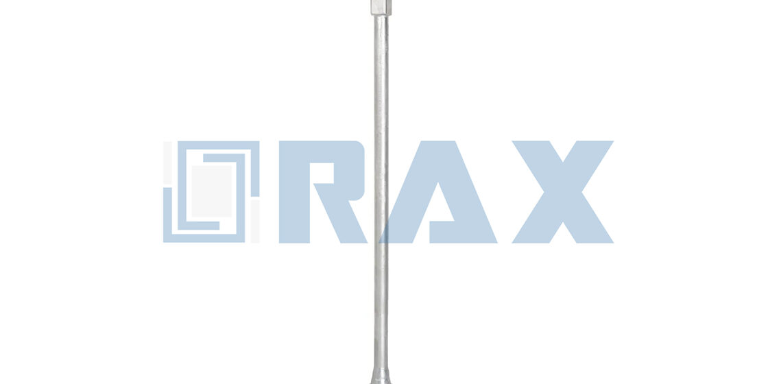
Galvanizing protects the steel backbone of your foundation from corrosion, but a thin spec sheet line rarely guarantees the coating survives the structural load cycle. Most project specs call for galvanized anchor rods and then skip the details that actually keep them standing. That gap costs you rejections. A 2-inch F1554 Grade 105 rod carries the structural demand, but its hot-dip coating cannot eat into the thread tolerance required by the spec. Portland Bolt qualifies every batch to that exact standard.
This breakdown covers three points that prevent failed inspections: sizing the rod against calculated guy loads and soil class. The second step locks in the correct UNC thread length before the kettle. The final step runs third-party coating checks that stop utility inspector rejections at the gate. You finish with a dispatch verification protocol that keeps dimensional tolerances and zinc thickness on spec.
Do Anchor Rods Follow Structural Steel Standards?
Class C governs hot-dip galvanizing thickness, not tensile strength. Confusing the two is the fastest route to site rejection. Material grade, coating class, and dimensional tolerance must be specified and certified as separate line items.
Class C Requirements: Coating Thickness, Not Tensile Strength
Let’s clear up a widespread specification error right away: "Class C" does not describe the tensile strength of an anchor rod. It defines the minimum hot-dip galvanized coating thickness under ASTM A123 and ASTM A153. Tensile and yield strength are controlled by entirely separate material grades, such as ASTM A36, A449, or utility-specific steel classifications. When a procurement document writes "ASTM A123 Class C tensile requirement," it creates an immediate engineering contradiction that buyers and inspectors rightfully flag.
- Class C Coating Standard: Sets the required zinc layer thickness, typically targeting a mean coating above 85 microns for power infrastructure, with strict minimums per base metal thickness.
- Tensile/Grade Standard: Controls ultimate and yield strength in ksi or MPa, verified through heat treatment, chemical composition, and mechanical testing unrelated to galvanizing.
- Procurement Reality: A rod can fully pass Class C coating requirements while still being rejected if the underlying steel grade certificate is missing, mismatched, or not tied to the shipped lot.
Structural Steel Versus Anchor Rod Specification Gaps
Structural steel specifications are engineered for static framework loads: beam-to-column connections, weldability, and flat-plate chemistry. Anchor rods for overhead line and renewable energy foundations operate under a completely different physical envelope. They face cyclic guy-wire tension, soil shear displacement, helix embedment mechanics, and long-term corrosion cycles where the zinc coating acts as both a barrier and sacrificial protection.
The danger appears when a project team applies general structural steel tolerances to helical or screw anchor rods. A 3mm shaft variance might be invisible on a cross arm brace, but it breaks torque-to-depth correlation on a no-wrench screw anchor, causing skipped embedment and sudden pull-out under storm loading. We run our anchor rod and screw anchor production on automated lines calibrated to a strict 1mm tolerance across shafts and helix welds because field installation data consistently shows that looser allowances destroy holding performance.
- Geometry Control: Anchor rods require helix pitch, diameter, and shaft concentricity specifications that standard structural steel codes simply do not define.
- Coating Behavior Over Weld Zones: Silicon content differences between base steel and weld filler metal cause uneven zinc flow. Generic structural galvanizing checks frequently miss localized thin spots that become early corrosion initiation points.
- Load Validation Methodology: Power grid anchors rely on in-house IEC 120 gauge testing and direct load validation, whereas structural steel typically depends on post-fabrication third-party coupon testing.
Project Code Rejection Prevention for Anchor Grades
Most anchor rod rejections are documentation failures, not hardware failures. Site inspectors reject shipments when the submittal package merges material grade and galvanizing class into a single ambiguous reference. To keep utility and solar foundation projects moving without stop-work orders, the purchase order and delivery certificates must treat grade and coating as independent compliance tracks.
Our QC protocol requires a double-review process where every production batch is inspected twice before packaging. We cross-reference heat numbers against galvanizing certificates, SGS verification reports, and load test logs. When an inspector requests the "anchor grade," they need to see the steel tensile classification and the coating class clearly documented on matching certification sheets, not inferred from a generic product name.
- Specification Separation: Write material grade, ASTM/ISO galvanizing class, shaft tolerance, and helix dimensions as distinct line items in the BoQ.
- Certificate Cross-Referencing: Ensure mill test reports explicitly link the steel grade to the shipped lot number and attach independent coating thickness verification.
- Regional Tender Alignment: Match the project jurisdiction’s preferred standard (ASTM, ISO, or IEC) before fabrication, since regional utilities frequently reject non-localized certification formats regardless of actual product quality.
Verify Tensile Strength Exceeds Calculated Loads
In firm soil conditions where anchor holding capacity is high, the galvanized anchor rod inevitably becomes the critical fuse in the system; rigorous tensile verification is the only defense against catastrophic failure.
Verifying Ultimate Tensile Strength Against Design Loads
Engineers must distinguish between the yield strength of the anchor rod and its ultimate tensile strength (UTS). While yield strength indicates the point of permanent deformation, the UTS represents the maximum stress the rod can withstand while being stretched or pulled before necking and rupture. For guy wire systems and critical pole line hardware, the design calculation must ensure that the UTS of the rod significantly exceeds the maximum calculated tension loads.
A common failure mode occurs when specifications only satisfy the yield requirement without accounting for dynamic loads such as wind gusts or ice accumulation. In these scenarios, the rod may stretch beyond its elastic limit, leading to sudden failure. Therefore, verification protocols should cross-reference the rod's material grade (e.g., ASTM F1554 Grade 55 or 105) against the factored load requirements of the specific utility grid to ensure the UTS provides a sufficient buffer above the service load.
Design Load Ratios for Galvanized Anchor Rods
The design load ratio, often referred to as the "utilization ratio," is the relationship between the actual service load applied to the guy wire and the allowable tensile capacity of the selected anchor rod. For instance, if a 3/4-inch diameter rod of high-strength steel offers an allowable capacity of approximately 17,500 lbs, and the calculated service load is 9,500 lbs, the utilization ratio is roughly 0.54 (or 54%). This indicates a comfortable safety margin, allowing for future load increases or unforeseen stress events.
Conversely, if a smaller diameter rod results in a utilization ratio approaching 0.80 or 0.90, the system is considered "overspecified" for current conditions but leaves no room for error. In B2B infrastructure projects, targeting a utilization ratio between 0.50 and 0.65 is often considered best practice. This balance optimizes material costs without compromising the structural integrity required for long-term utility deployments.
Required Safety Margins for Guy Wire Systems
Utility standards mandate specific safety factors (also known as factors of safety) to account for variations in material quality, installation inconsistencies, and environmental stressors. For overhead line construction, the required safety margin typically ranges from 1.5 to 2.0 times the maximum guy load. This means if the static tension on a guy wire is calculated at 10,000 lbs, the anchor rod and its connection hardware must be capable of withstanding at least 15,000 to 20,000 lbs without failure.
Verifying these margins requires calculating the "breaking strength" of the entire assembly. Specifiers must look beyond the guy strand's rating and confirm that the anchor rod's ultimate tensile strength, when reduced by the efficiency of the connection (e.g., clamp grip or threaded engagement), still meets or exceeds the mandated safety factor. Failure to rigorously apply this multiplier risks infrastructure collapse during high-load events such as storms.
Match Rod Diameter to Tensile Demand and Soil Class
Correct rod sizing hinges on balancing soil pullout resistance against steel tensile yield, preventing the shaft from becoming the system’s weakest link.
Decoding the Diameter Selection Logic
Engineers frequently treat anchor rod sizing as a simple lookup exercise, but field reality demands a more nuanced approach. A guy wire system must account for two competing variables simultaneously: the ground’s resistance to extraction and the steel’s ability to withstand tensile stress without permanent deformation. When a specification selects a diameter based solely on a generic load chart, it often ignores local geotechnical conditions. A rod that performs adequately in loose topsoil can fail catastrophically when driven into dense subgrades that develop far higher holding capacity than the shaft was designed to absorb.
Diameter selection is essentially a risk-mitigation strategy. Undersizing saves material cost upfront but creates a hidden failure pathway. Oversizing improves structural redundancy but increases shipping weight, handling difficulty, and procurement expense. The optimal choice lands precisely where the soil’s extractive force meets the rod’s verified yield capacity, leaving enough margin for dynamic loading, corrosion allowance, and long-term fatigue.
Aligning Shaft Size with Ground Conditions
Soil classification directly dictates how much tensile demand the anchor rod must survive. In non-cohesive, low-density substrates such as sand or loose clay, the surrounding earth yields relatively easily. The anchor develops holding power through surface area and helix engagement, meaning a smaller-diameter shaft is usually sufficient because the ground fails before the steel reaches its stress limit. Here, standard utility sizing prioritizes cost-efficiency while maintaining reliable performance.
As substrate density increases, the physics shift dramatically. Compact clay, gravel mixes, and fractured rock offer exceptional resistance, allowing the helix to develop massive pullout forces. In these conditions, the rod becomes the primary stress conductor. Three-quarter-inch profiles generally remain appropriate for lighter guy runs in forgiving ground, while one-inch shafts step up to handle moderate-to-high tension environments where firmer soils demand greater cross-sectional strength. When projects enter extreme-exposure zones characterized by heavy ice accumulation, sustained high-wind gusts, or seismic retrofit requirements, engineers typically move to 1-1/4-inch configurations to guarantee the assembly can absorb shock loads that would otherwise exceed standard utility limits.
Never assume a rod will fail by bending or loosening first. In dense soil, the anchor grip can vastly outstrip the steel’s tensile capacity. If the diameter is not upsized, the rod will snap suddenly under peak load, leaving the pole or tower completely unsupported with no visible warning signs.
Eliminating the Rod Strength Bottleneck
The most frequent cause of anchor rod overdesign is a lack of coordination between soil mechanics and steel grade selection. Procurement teams often specify diameter based on static calculations alone, forgetting that dynamic events like lightning strikes, vehicle impact, or rapid temperature swings introduce instantaneous load spikes. Applying aggressive safety multipliers ensures the assembly remains stable even when actual field conditions exceed design assumptions. For high-severity applications, designers routinely target factors well above the baseline 1.5x threshold, pushing toward 2.0x or higher to account for unpredictable stress concentration.
Manufacturing precision plays an equal role in preventing bottlenecks. Helix weld geometry must maintain strict dimensional tolerance so that installed torque correlates reliably to embedment depth. When shaft diameter, flight pitch, or weld integrity deviates from specification, crews lose confidence in torque-based verification. Consistent dimensional control guarantees that every rotation translates predictably into holding capacity, which is non-negotiable when designing for extreme environmental exposure or critical infrastructure stability.
| Rod Diameter | Tensile Demand Range | Target Soil Class | Design Safety Factor | Critical Engineering Note |
|---|---|---|---|---|
| 3/4" | Light to Moderate (<12,000 lbs) | Soft to Medium (Sand, Loose Clay) | 1.5x | Ideal for low-load guy wires; ensures hot-dip galvanizing meets >85 micron mean thickness per ISO 1461. |
| 7/8" | Moderate (12,000 – 15,000 lbs) | Firm to Hard (Compact Clay, Gravel) | 1.75x | Standard utility sizing; balances cost-efficiency with sufficient tensile strength to prevent rod yield in firm substrates. |
| 1" | High (15,000 – 18,000 lbs) | Hard Rock or High-Seismic Zones | 2.0x | Required when soil holding capacity exceeds lower rod grades; prevents dangerous rod failure before anchor pullout. |
| 1-1/4" | Maximum Capacity (15,000 – 18,000 lbs) | Extreme Wind, Ice Loading, or Seismic Retrofit | 2.0x+ | Utilizes precision-engineered helix welds with strict 1mm dimensional tolerance for maximum torque-to-depth correlation. |
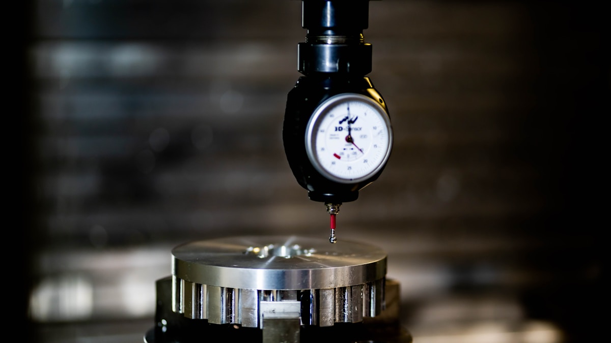
Specify UNC Threads and Required Thread Length
Specifying the correct UNC thread pitch and minimum engagement length ensures anchor rods maintain clamping force after hot-dip galvanizing while safely transferring guy wire and structural loads into the ground.
Anchor rod procurement failures frequently trace back to one overlooked detail: thread specification does not account for the finished galvanic coating or the required embedment geometry. When buyers order U-bolts, eye bolts, double-arming bolts, and helical screw anchors, the thread pitch must match the mating hardware, and the engaged length must satisfy both tensile demand and soil resistance. Using Fine Unified (UNF) threads on heavy-duty outdoor infrastructure is almost always a mistake; coarse pitch provides superior vibration resistance and tolerates minor dimensional deviations caused by industrial coatings.
Standard UNC Pitch Selection for Power Line Hardware
Unified National Coarse (UNC) remains the default thread series for galvanized anchor rods, guy clamps, and suspension fasteners. The coarse pitch leaves enough radial clearance to accommodate hot-dip zinc buildup without sacrificing structural integrity. Common configurations seen in pole line hardware include:
- 1/2" nominal: 13 threads per inch (TPI). Frequently used for light-to-medium guy wire assemblies and secondary rack mounting.
- 5/8" nominal: 11 TPI. Standard for primary overhead line tension applications and heavier cross-arm braces.
- 3/4" nominal: 10 TPI. Reserved for high-breaking-load environments, extreme soil classes, and utility tenders requiring elevated safety factors.
Selecting the wrong pitch creates immediate field friction. A 5/8"-11 UNC anchor rod will not accept a 5/8"-13 UNF nut, and forcing mismatched threads strips the softer zinc layer while damaging the underlying carbon steel. Tender documents should explicitly state the thread series, diameter, and pitch to prevent supplier substitutions.
Top vs. Bottom Thread Length Requirements
Partial threading is standard practice for anchor rods and structural fasteners. The top threads are typically longer than the bottom threads, allowing enough exposed length for wrench engagement, nut seating, and galvanic corrosion monitoring at the soil line. When bottom threads are included, their length depends directly on the thickness of embedded materials and the required development length within the foundation or soil matrix.
For helical screw anchors and no-wrench installations, thread length along the shaft determines how much torque transfers into the surrounding soil. A shaft that is fully threaded offers maximum surface area but increases drag during installation. Conversely, a smooth shank with localized top threading reduces soil displacement but limits embedment adjustability. Buyers should specify the exact threaded zone rather than assuming full-length threading.
Calculating Minimum Engagement Length
Minimum thread engagement is rarely a fixed number; it scales with the applied tensile load and the strength of the mating material. As a baseline engineering rule, the engaged thread length should equal or exceed 1.5 times the nominal rod diameter for standard steel-on-steel connections. For example, a 3/4" anchor rod requires at least 1.125 inches of engaged thread to develop near-full bolt strength under static loading.
- Nut engagement: Minimum 1.5× nominal diameter for static utility hardware.
- High-vibration guy wire systems: Recommend 2.0× nominal diameter or use prevailing torque nuts to prevent loosening.
- Embedded soil/screw anchor depth: Determined by soil class, helix plate geometry, and calculated pull-out resistance, not just thread pitch.
When designing for extreme cold-weather environments or coastal salt-exposure projects, engagement calculations must include corrosion allowance. A rod that meets minimum engagement today may fall below safe thresholds in fifteen years once the zinc layer degrades and the effective diameter shrinks.
Thread Clearance Specification for Hot-Dip Galvanizing
Hot-dip galvanizing deposits a metallic zinc coating that uniformly covers the anchor rod, including all machined threads. Industrial coatings commonly achieve a mean thickness exceeding 85 microns, with local peaks reaching well over 100 microns in thread crevices. This zinc accumulation physically reduces the internal thread diameter, making standard nuts impossible to thread onto the rod without intervention.
Procurement drawings must explicitly state whether threads require post-galvanizing re-tapping or pre-finished clearance to match the selected zinc coating thickness. There are three accepted specification pathways:
- Post-dip tapping: Threads are cut after immersion to restore dimensional clearance. This is the most reliable method for precision fasteners.
- Oversized pre-galvanized blanks: Threads are rolled or cut slightly larger before dipping, then finish within tolerance after zinc deposition.
- Masked uncoated zones: Protective caps or wraps preserve the top exposure during kettling, maintaining clearance for field assembly.
Plain carbon steel, hot-dip galvanized, and stainless steel variants all follow these same thread-clearance principles. The choice of finish depends on environmental exposure, but the dimensional requirement for UNC engagement never changes.
Zinc accumulation within thread profiles poses a significant installation risk that requires immediate verification. Zinc buildup in the thread crests and roots will strip nuts during installation or create false preload readings. Always verify thread gauge clearance after galvanizing before approving a shipment.
Request thread inspection reports alongside coating certification and load-test documentation. Confirm that the top threaded zone length matches the drawing, the UNC pitch is verified with a go/no-go gauge, and the hot-dip coating thickness remains within ISO 1461 tolerance bands.

Check Shaft Straightness and Helix Geometry
Shaft straightness and helix geometry are the primary determinants of installation efficiency and load transfer. A bent shaft or misaligned helix creates eccentric loading, which compromises the anchor's holding capacity and can lead to premature pull-out failure.
The Critical Role of Shaft Straightness
For helical anchors and screw rods, straightness is not merely a cosmetic standard; it is a functional requirement for safe installation. When a shaft deviates from a true linear axis, the anchor exerts lateral force on the soil during installation rather than purely vertical penetration. This increases installation torque exponentially and can shear the lead section or cause the shaft to bind, preventing the anchor from reaching the designed embedment depth.
Thermal distortion during manufacturing requires strict adherence to straightness tolerances to maintain structural integrity. This vulnerability is most pronounced in "no-wrench" configurations where a forged eye is welded directly to the shaft, as uncontrolled heat treatment or welding processes can induce thermal bowing. To mitigate this, ASTM F1554 specifies a straightness limit of L/1000, meaning a standard 66-inch anchor rod must not deflect more than approximately 0.066 inches over its length. Any significant bend introduces eccentricity that acts as a lever arm, converting pure tensile forces into unintended bending moments that the steel rod was not primarily designed to sustain.
Helix Geometry and Pitch Consistency
The geometry of the helix—specifically its pitch, centrality, and perpendicularity—governs how efficiently the anchor displaces soil. The helix must be positioned strictly perpendicular to the shaft axis. If the plate is skewed or welded at an angle, the anchor will "wobble" as it penetrates the ground, creating a void around the shaft. This void significantly reduces the skin friction and passive pressure required for long-term holding capacity.
Furthermore, the pitch (the distance between helix blades on multi-helix anchors) must match the design specifications to ensure that the soil between the blades is engaged effectively without interference. A common failure mode in lower-quality anchors is poor weld penetration at the helix-to-shaft connection. If the weld is slag-filled or incomplete, the helix can spin freely on the shaft during installation ("slipping"), resulting in zero load transfer to the surrounding soil mass.
Verification Protocols for Field Receiving
To mitigate the risks of structural failure, procurement specifications must include verification protocols for these geometric parameters. Visual inspection is often insufficient for detecting subtle thermal warping.
- Shaft Alignment Check: Roll the anchor rod on a flat, level surface. A straight rod will maintain consistent contact along its length; a bent rod will wobble or pivot, revealing high points of deflection.
- Helix Perpendicularity: Use a carpenter's square or a specialized gauge to measure the angle between the helix plate and the shaft. The deviation should not exceed 2 to 3 degrees from a perfect 90-degree angle.
- Weld Integrity Assessment: Inspect the weld bead at the helix connection. It should be uniform and full-width. Look for signs of undercutting or porosity, which indicate weak points susceptible to cracking under high torque loads.
Protect Threads and Address Zinc Buildup
Zinc accumulation turns precision anchor rods into field headaches. Protecting thread geometry and managing weld-zone alloy growth keeps every unit installable at scale.
Thread Clearance Maintenance After Hot Dip Immersion
Hot-dip galvanizing is a metallurgical reaction, not a simple surface coat. When steel enters the molten bath, iron-zinc intermetallic layers grow outward, reducing the effective diameter of every exposed surface. For anchor rods, that dimensional shift is enough to bind nuts, lock couplers, and seize driving threads before they ever reach the installation site.
Procurement teams frequently conflate ASTM A123 requirements for structural shapes with A153 for smaller hardware. Anchor rods consume different chemical environments in the kettle, and expecting identical minimum coating weights across both specifications creates ordering mistakes. The real risk is not just total thickness; it is uneven build-up on the thread crests and root. When clearance is not calculated upfront, bulk shipments arrive with hundreds of units that look perfect visually but fail a hand-tight engagement test.
Our engineers design the dipping orientation and mask critical mating surfaces to preserve functional diameter. For high-volume runs, we leave designated ungalvanized grip lengths on drive threads where field assembly demands zero interference. Fully dipped fasteners are clearance-tapped to the correct pitch diameter before packaging. Specifying these protections during the quote phase eliminates costly field grinding and keeps project schedules on track.
- Mating Surface Protection: Use temporary caps or leave intentional uncoated zones on coupler threads to prevent zinc bridging during immersion.
- Clearance Tapping Protocol: Run taps to the calculated pitch diameter after cooling, verifying nut engagement without force before palletizing.
- Field Rejection Trigger: Any anchor rod that cannot be hand-threaded by a qualified installer must be quarantined, not forced, to avoid stripping the protective coating.
Zinc Buildup Management Around Weld Zones
The helix-to-shaft junction is where galvanizing chemistry gets messy. Base steel and weld filler metal have different silicon responses. When that joint hits the molten bath, the alloy layer grows unevenly. The result is a rough, excessive deposit right over the weld seam. It compromises thread engagement, distorts helix pitch, and makes torque readings unreliable during installation.
This inconsistency is rarely visible during a quick visual inspection. A rod can look smooth from a distance but carry a hard zinc lump exactly where the nut needs to seat. In our experience, the difference between a clean weld zone and a failed coating lies in the pre-dip preparation. Strict chemical cleaning breaks down mill scale uniformly, while controlled fluxing ensures the zinc reacts evenly across dissimilar metal boundaries.
Automated production lines help here because they hold dimensional tolerances tighter than manual setups. When shaft straightness and helix geometry are verified before immersion, the zinc has fewer irregular surfaces to overbuild. We also monitor the kettle chemistry and immersion time to prevent the iron-zinc reaction from running past the optimal alloy band. The goal is a uniform metallic finish that protects the weld without creating installation friction.
Silicon variance between base metal and weld filler drives uneven coating. Pre-dip cleaning and kettle timing control the reaction more than post-process grinding ever could.
Post-Galvanizing Thread Tapping Procedures for Anchor Rods
Sometimes the zinc layer builds up exactly where it should not. Cold re-tapping is acceptable for minor buildup, but aggressive accumulation requires a controlled hot-tap procedure. Cutting while the steel is warm allows the tap to shear the iron-zinc intermetallic layer cleanly without shocking the surrounding coating.
Forcing a standard tap through a fully coated rod at room temperature creates two common failures. Either the tool digs into the base steel, weakening the thread root, or it leaves zinc plugs lodged in the thread flanks. Both conditions create hidden stress concentrators. Under guy-load tension or seismic movement, those plugs become crack initiation points long before the anchor reaches its rated holding capacity.
Field modifications such as grinding seized threads compromise the protective coating and expose critical load-bearing surfaces. Stripping the zinc at a high-stress contact point exposes bare steel to rapid corrosion exactly where the assembly bears the most load. If a thread does not engage smoothly, replace the component rather than salvage it in the field.
Verification closes the loop before the rod leaves the facility. Every tapped thread undergoes a two-stage measurement check. Gauges verify pitch diameter, thread form, and engagement depth. Mechanical integrity remains the priority, ensuring the protective layer is intact and the load path is never compromised by rework damage. When a batch clears these gates, the only remaining variable is proper storage and handling at the installation site.
| Technical Parameter | Specification | Methodology | Engineering Advantage |
|---|---|---|---|
| Galvanizing Compliance | ISO 1461, ASTM A123/A153 Class C | SGS-Certified Hot-Dip Process | Validated Corrosion Resistance |
| Coating Thickness | Mean >85 Microns | Advanced Galvanizing Kettle Technology | Superior Corrosion Shielding |
| Dimensional Tolerance | ±1mm Precision | Automated Production & Machining | Mitigates Zinc Buildup Interference |
| Surface Finish | Smooth, Bright Zinc | Strict Chemical Cleaning & Dipping | Optimized Thread Engagement |
| Quality Control | 100% Double Inspection | 10-Person Dedicated QC Team | Validates Structural Integrity per IEC 120 |
Validate Coating and Strength Before Shipping
Third-Party Coating Thickness Verification Protocols
Corrosion resistance is the primary determinant of an anchor rod's service life, making coating verification a non-negotiable step in quality assurance. The industry frequently encounters confusion between ASTM A123 and A153 specifications; A123 typically governs structural steel shapes with thicker coating requirements, while A153 applies to fasteners and smaller hardware. For galvanized anchor rods, adhering to a unified standard is critical to ensure the zinc layer provides adequate sacrificial protection without compromising thread fitment.
Validation must rely on precise magnetic induction gauge testing rather than visual inspection alone. While many competitors accept the minimum allowable averages, we strictly adhere to a mean coating thickness exceeding 85 microns in compliance with ISO 1461. This specific threshold ensures superior protection against soil corrosion. To eliminate any ambiguity in the supply chain, our protocols include SGS certification for every batch, providing documented proof that the coating weight meets the rigorous demands of global utility markets.
IEC Gauge Testing for Galvanized Anchor Rods
Beyond surface protection, the mechanical integrity of the galvanized rod must be validated against the loads it will encounter in the field. The IEC 120 standard serves as the benchmark for evaluating the mechanical strength of overhead line hardware. Verification protocols should simulate ultimate failure conditions to ensure that the rod—not the soil—is never the weakest link in the guy wire system.
In-house testing must be rigorous enough to replicate real-world tension. We conduct load testing that validates holding capacities up to 18,000 lbs, ensuring that every unit exceeds the safety margins required for high-voltage transmission. This gauge testing confirms that the hot-dip galvanizing process has not embrittled the steel and that the weld integrity remains intact under stress. By validating these parameters against IEC standards prior to packaging, you mitigate the risk of on-site failures during tensioning.
Mechanical Integrity Checks Prior to Dispatch
The final dispatch phase is where dimensional accuracy and visual defects are intercepted. Advanced manufacturing relies on automation to maintain consistency, but human verification remains essential for catching outliers. A robust quality control protocol should enforce a 100% inspection rate, specifically checking for straightness and dimensional tolerance within 1mm across the shaft and helix welds.
Our facility utilizes a dedicated 10-person QC team to enforce a double-review process. This means every anchor rod undergoes two separate inspections—first for dimensional conformity and second for surface finish and packaging integrity—before it leaves the factory floor. We verify that the automated welds are free of porosity and that the galvanized finish is smooth and bright, free of ash or drips that could impede installation. For B2B buyers, this level of scrutiny ensures that what arrives on the project site requires no rework, allowing for immediate deployment into critical infrastructure.
📋 Actionable Steps
- Step 1: Request the Coating Inspection Report verifying mean thickness (>85 microns) per ISO 1461.
- Step 2: Review the load test data referencing IEC 120 standards to confirm ultimate tensile capacity.
- Step 3: Validate the Final Inspection Checklist to ensure the "Double-Review" process was completed.
Conclusion
Getting the diameter right is the easy part. Managing that zinc buildup after hot-dip galvanizing? That is where projects stall. You must specify UNC threads clearly and plan for post-dip thread tapping, or your nuts simply will not fit. Do not assume standard clearances work once the coating hits the weld zones. Verify the ASTM A123 thickness yourself, because a micron of coating variance can ruin the torque spec.
Our engineering team runs IEC gauge testing on every batch to catch these thread issues early. We prioritize mechanical integrity over speed, ensuring every rod passes third-party verification protocols. If you are unsure about soil class interactions or specific helix geometry, rely on our technical support. We help you validate coating and strength details long before the trucks roll out.
Frequently Asked Questions
What defines an anchor rod?
An anchor rod is a steel fastening device used to attach a structure to its foundation or the ground. It is essential for resisting tension, shear, and vibration forces in overhead lines and towers. These rods are typically hot-dip galvanized to withstand harsh environmental exposure.
What is the difference between rods and bolts?
Anchor rods are typically longer, threaded at one end, and designed to embed into concrete or soil to secure structures. Bolts are generally shorter, fully or partially threaded, and used to clamp components together. Rods focus on tension and anchoring, whereas bolts focus on clamping force.
What determines galvanizing thickness standards?
Galvanizing thickness is primarily determined by the steel's chemical composition and surface area, governed by standards like ASTM A123 and A153. Thicker coatings are typically required for severe environments to ensure longer service life. Manufacturers must adhere to these minimum thicknesses to guarantee corrosion resistance.
What are the common applications?
Galvanized anchor rods are widely used in utility pole guying, transmission towers, and solar panel foundations. They provide critical support to stabilize structures against lateral forces and tension loads. Their corrosion resistance makes them suitable for diverse environments including industrial and coastal regions.
Why is installation important?
Correct installation ensures that the anchor achieves its designed holding capacity and maintains structural stability. Improper torque or depth can lead to soil failure or excessive stress on the rod itself. Following manufacturer guidelines is essential to validate engineering calculations and ensure long-term safety.