
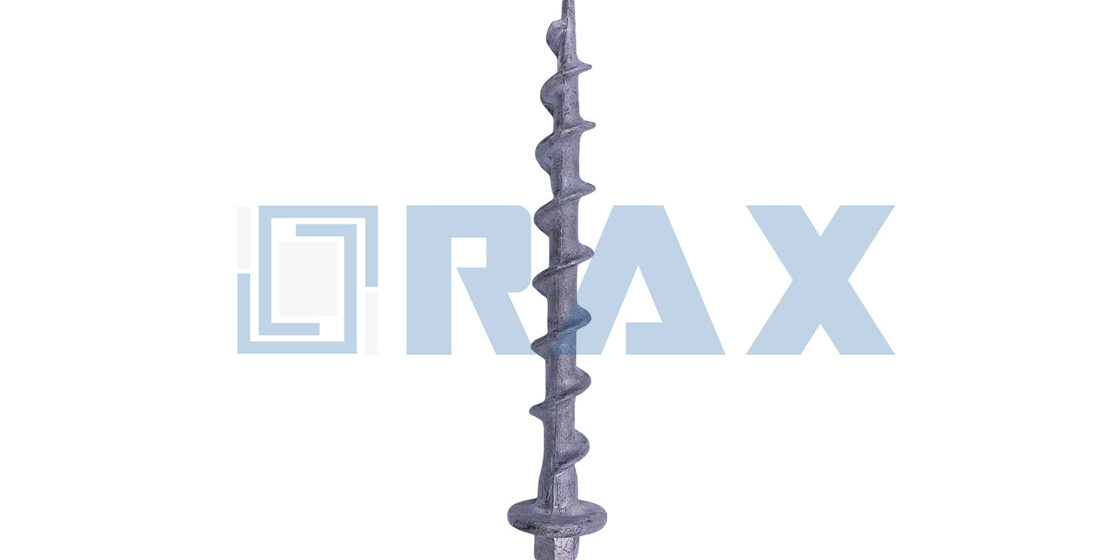
Traditional earth anchoring often relies on heavy torque wrenches that slow down guying operations and complicate logistics. The no wrench screw anchor eliminates that bottleneck by allowing direct drive insertion with a standard bar or machine adapter. These anchors, built from hot-dip galvanized steel to meet ASTM A153 Class C standards, handle demanding installations with a maximum installing torque of 2,300 ft.-lbs on a 1-1/4 inch diameter rod.
This guide examines the torque transfer mechanics of drive rods versus bars, along with precise load capacity charts for varying soil classes. You will see how galvanizing uniformity exceeding 85 microns prevents corrosion in aggressive environments. Upgrading your specs to this design reduces crew time while ensuring your utility poles meet strict safety audits over a 20-year service life.
How Traditional and No-Wrench Anchors Drive In
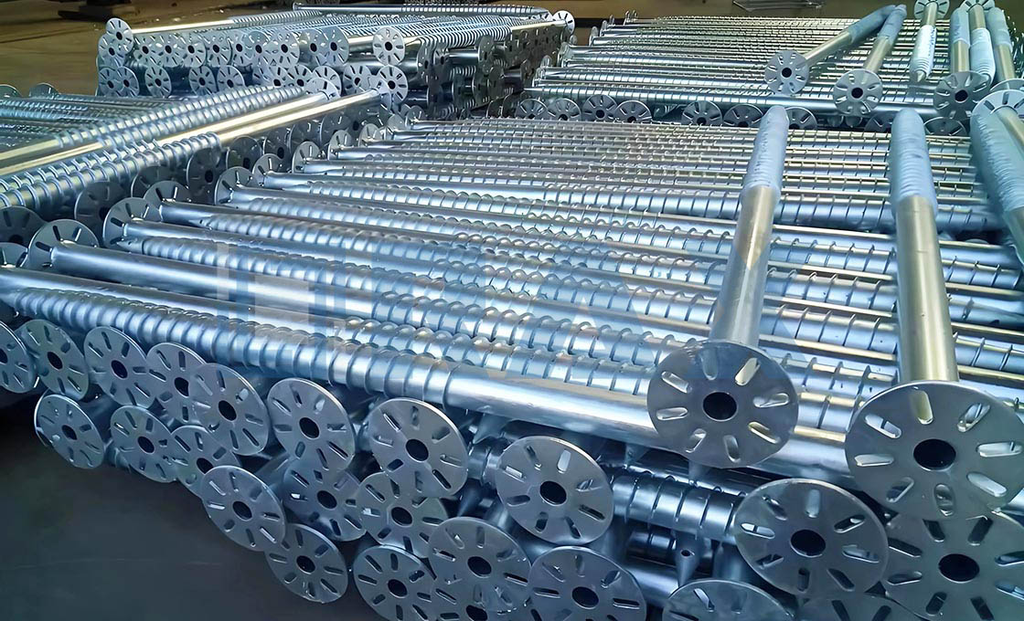
The driving interface determines how efficiently rotational force reaches the soil. No-wrench anchors remove coupling friction and setup drag, delivering a continuous torque path and faster deployment per unit.
Torque Transfer Pathways
Traditional rod-driven systems introduce a mechanical bottleneck at every coupling point. When a drive rod threads into the anchor body, torsional energy must pass through that joint before reaching the helix or driving face. In dense ground conditions, that connection becomes the weakest link, often slipping under peak load and forcing crews to reset repeatedly.
No-wrench anchors solve this by creating a continuous torque path from the turning bar straight into the anchor shaft. Because the driving interface is integrated into the forged body, there is no secondary thread to strip or align. We consistently observe that this direct-drive architecture maintains rotational consistency even when operators push past standard resistance thresholds, which is where traditional couplings tend to fail first.
Leverage Mechanics for Soil Penetration
Soil penetration relies on sustained shear force along the anchor flights or plates. The leverage ratio available to the installer controls how much torque can be applied safely without buckling the hardware. Standard bars engaged with a wide integral hub give the operator a longer moment arm, allowing smooth, controlled rotation rather than percussive impact. That controlled input keeps the anchor tracking true instead of deflecting off rocks or compacted layers.
From an engineering standpoint, the metal flow matters as much as the geometry. Hot-forged anchor bodies preserve a continuous grain structure that handles torsional stress far better than cast equivalents. When high torque is applied through a leveraged bar, the forging resists micro-fractures at the eye or hub throat. Our lab checks during IEC 120 load verification confirm that forged torque paths retain structural integrity under repeated peak loading.
Installation Speed Impact of Eye Designs
Field speed is rarely limited by the anchor’s holding capacity; it is limited by how fast a crew can deploy unit after unit. Traditional setups require managing multiple rod segments, threading couplings, and constantly adding length as depth increases. No-wrench designs eliminate that staging overhead. A standard bar engages immediately, and the crew can advance depth without interrupting the rotation cycle.
The physical configuration of the eye directly influences that rhythm. Larger opening geometries accommodate thicker turning bars, which improve grip security and reduce bar slippage during high-torque turns. Triple-eye arrangements add multi-point contact surfaces, stabilizing the bar position when operators need maximum leverage in stubborn soil. Precision manufacturing keeps these hubs concentric under load, ensuring the bar stays seated rather than walking out mid-rotation.
For contractors pulling volume through utility or solar foundation projects, that cumulative time saving translates directly into labor cost control. Fewer setup steps mean more anchors driven per shift, and the reduced handling of separate drive rods cuts down on lost or damaged equipment at the jobsite.
| Anchor Type | Driving Mechanism | Installation Efficiency | Primary Application | Rax Quality Standard |
|---|---|---|---|---|
| Traditional Rod-Driven Anchors | Installed using a separate drive rod and impact tools to reach required depth. | Moderate; requires tool setup and rod extraction after installation. | Deep foundation for heavy utility poles and transmission structures. | Hot-forged steel, ISO 1461 galvanizing (>85 microns), IEC 120 tested. |
| No-Wrench Screw Anchors | Driven directly via integral eye or hub using standard bars; no separate drive rod needed. | High; rapid deployment with minimal manpower and equipment. | Light to medium duty guying, solar foundations, and residential anchors. | Precision manufactured, ISO 1461 galvanizing (>85 microns), SGS verified. |
| Cross-Plate & Expanding Anchors | Driven into soil where plates expand or lock upon withdrawal of the driving spear. | Moderate; requires precise technique and drive spear extraction. | Guys for distribution lines and areas with specific soil density requirements. | Hot-forged steel, ISO 1461 galvanizing (>85 microns), 100% double-review QC. |
Save Time by Ditching Heavy Torque Tools
No-wrench screw anchors cut field mobilization time by removing the need for heavy rotary torque rigs. Their impact-ready drive interfaces, optimized helix pitch, and manual-to-compact-machine adaptability let crews install anchors in fewer passes with lighter equipment.
Traditional screw anchor installations often bottleneck utility projects because crews must coordinate heavy rotary torque equipment, safety-perimeter zones, and multi-person rigging just to drive a single anchor. No-wrench screw anchors remove that mechanical dependency from the critical path. By designing the drive interface, helix geometry, and thread pitch to accept direct hammer impact, manual turning bars, or compact drilling-machine adapters, these fasteners shift the installation sequence from equipment-heavy to crew-light.
Field Workflow Elimination
The hardware accepts a simple driving rod or open-eye configuration that mates with standard site equipment. Operators can hammer the unit into pre-drilled conditions, rotate it with a handheld bar, or mount it on a rotary drill adapter. This flexibility collapses the mobilization window for remote pole-line and solar foundation jobs where bringing a torque rig to every anchor point is neither practical nor cost-effective.
- Drop-Forged Steel Construction: Eliminates deformation risk during impact driving, allowing rapid placement without pre-torque conditioning.
- Welded Helix Geometry: Optimized pitch transfers axial load efficiently, reducing the rotational force required per foot of penetration.
- Extension Rod Compatibility: Allows crews to reach firmer strata without swapping anchor assemblies mid-installation.
Deployment Economics at Scale
For high-volume utility deployments, the absence of heavy torque tools translates directly into schedule compression. A standard installation sequence can drop from a multi-equipment mobilization cycle to a single-pass crew operation. Maximum installing torque ratings remain within manageable human or compact-machine limits, with verified thresholds reaching approximately 2300 ft.-lbs. for 1-1⁄4-inch diameter rods under controlled conditions.
This reduction in peak torque demand means crews can maintain consistent drive rates across large right-of-way stretches. Fewer equipment failures, lower fuel consumption, and reduced operator fatigue compound over hundreds of anchor points, turning what was previously a slow, rig-dependent process into a streamlined production line.
When planning high-volume installations, specify 1-1⁄4-inch rod diameters for deep-drive applications. The larger cross-section distributes torque loads more evenly across the helix weld, preventing premature stripping during rapid manual or machine-driven cycles.
Never assume shallow-drive assumptions apply across all soil classes. If crews encounter unexpectedly dense layers, forcing the anchor past resistance without verifying soil density can damage the drive interface. Pre-scan ground conditions and adjust drive depth expectations before committing full equipment to the line.
Will the Anchor Hold Under Your Expected Load?
An anchor's capacity is determined by the weaker link: the steel's tensile strength or the soil's shear resistance. Accurately calculating the safety factor between Ultimate Holding Capacity (UHC) and Rated Working Load (RWL) is the only way to prevent catastrophic pull-out failure.
When specifying earth anchors for utility or solar foundations, assuming a standard "rated capacity" is sufficient is a critical engineering error. The actual load performance is a dynamic variable dependent on two distinct systems: the structural integrity of the steel anchor itself and the geotechnical properties of the soil. A failure in either system results in total foundation failure. For B2B buyers, the focus must shift from simple catalog numbers to analyzing the relationship between installation torque, soil density, and load safety factors.
Differentiating Ultimate vs. Working Load
To ensure grid stability, engineers must distinguish between Ultimate Holding Capacity (UHC) and Rated Working Load (RWL). UHC represents the maximum load the anchor can sustain in specific soil conditions before failure occurs, either by soil shearing or anchor fracture. However, utility infrastructure requires a significant safety buffer. Typically, a safety factor of 4:1 is applied for critical guying applications. This means if a specific project requires a holding capacity of 5,000 lbs (22.2 kN), the installed anchor system must demonstrate an Ultimate Holding Capacity of at least 20,000 lbs (88.9 kN) in field tests.
Relying on the RWL without verifying the UHC in specific site conditions invites risk. The published RWL is merely a guideline based on average soil classes. If the on-site soil is looser or more saturated than the "average" assumption, the UHC drops, effectively shrinking the safety factor. Rigorous validation protocols, such as IEC 120 load testing, are essential to confirm that the ultimate capacity aligns with the theoretical calculations before the grid goes live.
The Variable of Soil Class on Tensile Strength
The anchor itself is only the delivery mechanism; the soil provides the actual resistance. In high-density clay or compacted gravel, a 1-inch diameter screw anchor can achieve ultimate holding capacities ranging from 6,000 to over 11,000 lbs, provided the helix is placed at the correct depth. However, in sandy or loose loam soils, that same anchor may experience immediate pull-out at fractions of those loads.
This variance necessitates a site-specific approach to load calculation. Engineers cannot simply select an anchor based on rod diameter; they must calculate the required surface area of the helix needed to generate sufficient bearing pressure against the soil. For instance, in weaker soil classes, expanding the helix diameter or using multi-helix configurations is often required to distribute the tensile load over a larger surface area, thereby increasing the UHC to acceptable safety levels.
Structural Integrity and Torque Resistance
While soil often dictates the limit, the anchor must be structurally capable of transferring the load. Hot-forged manufacturing processes are critical here, as they align the steel's grain flow to enhance tensile strength and fatigue resistance. This metallurgical advantage ensures that the anchor rod can withstand the twisting forces required to reach the necessary installation depth without snapping—a common failure point in cast or lower-grade steel alternatives.
Furthermore, installation torque serves as the primary field indicator of capacity. There is a direct correlation between the torque required to install the anchor and its ultimate holding power. If an anchor achieves the target installation torque without shearing, it provides a probabilistic guarantee that the soil is engaging the helix correctly. Therefore, specifying anchors with high torque ratings is not just about ease of installation; it is a validation step that ensures the anchor will hold under the expected tensile loads of the transmission line.
| Engineering Feature | Specification | Load Reliability Benefit |
|---|---|---|
| Anchor Variants | Helical, Expanding, Cross-Plate, No-Wrench Screw | Optimized ground grip for diverse soil conditions in power and solar foundations |
| Structural Fabrication | Hot-Forged Manufacturing | Enhanced grain flow delivers superior strength and torque resistance versus cast alternatives |
| Surface Protection | ISO 1461 Hot-Dip Galvanizing | Mean coating thickness exceeds 85 microns, preventing corrosion-induced structural degradation |
| Performance Validation | In-House IEC 120 Load Testing | Rigorous gauge and load verification ensures every unit meets rated capacity standards |
| Inspection Protocol | SGS Certified / 100% Double-Review | Dedicated 10-person QC team guarantees dimensional accuracy and consistent load capacity |
Which Soil Types Support the No-Wrench Design?
Soil Classification & Bearing Capacity Requirements
No-wrench screw anchors perform optimally in cohesive and granular soils with adequate density and shear strength. Clay, silty clay, compacted silt, and dense sand provide the primary substrate classes where helical anchor engagement translates to reliable holding capacity.
The no-wrench design relies on continuous helix penetration without external drive tools, making soil consistency critical during installation. Uniform soil profiles allow the anchor to advance smoothly while maintaining torque response that indicates proper embedment.
- Cohesive Soils (CL, CH classifications): Clay and silty clay offer high bearing capacity and resist anchor pull-out through soil adhesion and cohesion. Ideal for utility pole guy wires and structural anchoring applications.
- Compact Granular Soils (SP, SW): Well-graded sand and gravel provide friction-based holding capacity. Anchor performance depends on relative density; loose sand requires greater installation depth to achieve equivalent load ratings.
- Silty Sands (SM): Mixed soil profiles with moderate cohesion and drainage characteristics. Suitable when density is achieved through compaction or natural stratification.
- Organic Soils (OL, OH): Peat and highly organic substrates lack sufficient bearing capacity and should be avoided. Screw anchors cannot develop reliable holding strength in decomposing material.
Installation Depth & Soil Density Correlation
Soil density directly determines minimum embedment depth for no-wrench screw anchors. Denser substrates allow shallower installation while maintaining load capacity, whereas lower-density soils require deeper helix engagement to distribute tensile forces across adequate soil volume.
Extension rods enable deeper placement in firmer soil layers beneath softer surface strata. This capability is particularly relevant for projects requiring load capacities that exceed what shallow helix configuration can deliver in single soil horizon.
Rock, boulder-heavy substrates, and frozen ground prevent helix penetration regardless of anchor design. Conduct geotechnical survey before specifying screw anchor foundation systems for these conditions.
Moisture & Corrosion Environment Considerations
Saturated soils and fluctuating water tables accelerate corrosion on embedded anchor components. While hot-dip galvanizing per ISO 1461 provides baseline protection with mean coating thickness exceeding 85 microns, aggressive soil chemistry—low pH, high sulfate, or chloride contamination—requires additional corrosion allowance or protective coatings for long-term durability.
Soil resistivity testing helps determine corrosion potential. Substrates with resistivity below 3,000 ohm-cm typically indicate elevated corrosion risk and should be accounted for in anchor specification and maintenance planning.

When Tight Spaces Require a No-Wrench Anchor
In confined urban easements or rocky terrain where heavy machinery cannot access, no-wrench anchors provide a critical solution by allowing installation using manual drive rods or impact hammers, negating the need for wide rotational swing arcs or hydraulic torque heads.
The primary driver for selecting no-wrench anchors is physical clearance. In dense residential or commercial developments, utility poles are frequently situated in easements less than three feet wide, flanked by fences, retaining walls, or landscaping. Standard screw anchor installation requires a torque multiplier or a large drive rod with a handle that sweeps a significant arc to generate advantage. In tight spaces, this lateral movement is often impossible. No-wrench variants are engineered to be driven by a simple slide bar or impact hammer, requiring only vertical clearance to operate. This allows crews to install secure guy wire foundations without damaging surrounding infrastructure or obtaining expensive Right-of-Way variances for heavy machinery access.
Impact-Driven Mechanisms for Zero-Clearance Zones
For the most restrictive environments, such as alleyways with overhead obstructions or trench foundations in pre-constructed solar farms, certain no-wrench designs utilize impact-driven technology rather than rotational torque. These anchors feature a specialized eye or drive stud designed to withstand repeated hammer blows from a jackhammer or manual sledge. Advanced versions of these anchors incorporate a serrated shaft or a specific expansion mechanism. As the anchor is hammered into the substrate, the threads or serrations displace the soil, creating a high-density zone that offers pull-out resistance comparable to rotated screws. This method is particularly effective in rocky or hard-pan soils where traditional screwing might cause the anchor to walk or deflect off stones.
Durability Specifications for Hard-to-Access Locations
Because anchors installed in tight spaces are notoriously difficult to inspect or replace once the surrounding area is built up, material durability is a non-negotiable specification. B2B buyers must prioritize anchors that utilize hot-dip galvanizing compliant with ISO 1461 standards. In high-quality manufacturing, this process ensures a mean coating thickness exceeding 85 microns, providing a solid defense against soil corrosion that exceeds the minimum industry requirements. This longevity is vital for urban applications where excavation for maintenance is cost-prohibitive.
- Reduced Footprint: Profile diameters typically range from 3/4 inch to 1-1/4 inch, allowing penetration between underground utilities or root systems without extensive trenching.
- Drive Rod Compatibility: No-wrench eyes are sized to accept standard 1-inch or 1-1/4 inch drive rods, ensuring crews can use existing inventory without specialized adapters.
- Minimized Disturbance: The installation method displaces soil rather than removing it, preventing settlement issues in adjacent landscaped areas or hardscapes.
Where No-Wrench Anchors Beat Traditional Screw Anchors
Structural Reliability Over Traditional Screw Anchors
Traditional screw anchors introduce a mechanical weak link at the drive interface. When a crew torques a standard earth anchor, the drive rod transfers rotational force, but the holding integrity depends heavily on operator consistency and tool alignment. No-wrench screw anchors eliminate this variable by integrating the helix directly into the shaft body, creating a continuous load path from soil engagement to conductor attachment.
For utility buyers specifying hardware for critical circuits, this design shift matters more than installation convenience. The absence of a detachable drive coupling means there is no secondary point that can shear, strip, or loosen under sudden pole line tension. The anchor performs according to its engineered geometry, not according to how precisely a technician operates a torque wrench.
- Integral Forged Body: The helix is welded or forged directly onto the shaft unit, preventing the drive-rod separation that commonly plagues traditional screw anchors under shock loading.
- Pre-Mounted Thimble Eyes: Configurations such as 3/4 × 4 × 54 thimble eye models ship ready for cable attachment, removing the need for field-welded or bolted hardware that can fatigue over time.
- Hot-Forged Grain Structure: Forging aligns the metal grain along the shaft contour, delivering higher tensile yield strength compared to cast or machined traditional anchor heads.
Utility Projects Where the No-Wrench Variant Excels
Distribution guying is the primary high-reliability use case. When a pole line carries lateral conductor tension, the anchor must absorb dynamic shifts without slipping. A traditional screw anchor relies on perfect threading into the soil, whereas the no-wrench helix acts as a self-positioning device that achieves consistent embedment regardless of minor surface irregularities or uneven torque application.
Temporary stabilization projects operate under the same reliability requirements. Storm response crews and construction contractors frequently work in unpredictable ground conditions where installation delays or failed embedment can halt critical operations. Because the no-wrench design eliminates the separate drive coupling, the anchor maintains consistent performance even when standard torque protocols are difficult to follow in the field.
In both scenarios, the no-wrench variant converts installation risk into structural certainty. The buyer gets a hardware solution that holds its rated engagement because the load transfer is built into the component itself, rather than depending on external tooling compatibility or technician experience levels.
How Galvanizing Protects Against Long-Term Corrosion
Hot-dip galvanizing under ISO 1461 is non-negotiable for long-lived pole line hardware. A mean coating above 85 microns prevents premature rust in aggressive soils and eliminates costly field replacements.
ISO 1461 Compliance and Coating Uniformity
In the B2B hardware sector, vague claims of "galvanized finish" are a major red flag. Without strict adherence to ISO 1461, the coating lacks the metallurgical bond required for long-term service. This standard governs the mass of zinc coating and the adherence of that coating to the base steel, ensuring it does not flake or peel during handling or installation.
Achieving uniformity is where the process often fails in low-cost manufacturing. In our facility, we maintain a dedicated 10-person QC team to monitor every stage of the galvanizing process. We ensure that the zinc-iron alloy layers form consistently across complex geometries, such as the curved surfaces of pole bands and the threads of anchor rods. This uniform coverage is critical because corrosion almost always initiates at the thinnest point of the coating or where impurities exist.
The Significance of Exceeding 85 Microns
Thickness is the primary metric for service life estimation. While many competitors aim for the minimum acceptable threshold to save on raw material costs, we strictly adhere to a mean coating thickness exceeding 85 microns. This specification is not arbitrary; it is designed to outperform standard ASTM A153 Class C requirements, providing a substantial buffer against environmental wear.
A coating thickness above 85 microns offers a predictable lifespan extension, reducing the total cost of ownership for utility projects. It provides ample material to withstand the inevitable abrasions that occur during transport and the mechanical stress of torquing during installation. Our SGS-verified processes confirm that this thickness is maintained not just on the surface, but in critical threaded areas where corrosion often starts unnoticed.
Galvanizing Performance in Aggressive Soil Environments
Underground hardware faces the harshest conditions on the grid. Aggressive soils containing high moisture content, chlorides, or fluctuating pH levels can accelerate corrosion rates exponentially. In these environments, the zinc layer acts as a sacrificial anode. Even if the underlying steel is exposed due to a scratch or installation damage, the surrounding zinc corrodes preferentially to protect the iron.
For products like earth anchors and guy anchors, which are fully submerged in soil for decades, this electrochemical protection is vital. We have observed that our combination of hot-forging—which produces a dense, non-porous steel surface—and heavy galvanizing ensures the structural integrity of the anchor remains intact long before the zinc coating is depleted. This reliability is essential for projects in regions with high soil corrosivity, where excavation for repairs is financially prohibitive.
Conclusion
Torque specs matter less when your crew swings a hammer into clay versus compacted sand. The driven anchor wins on site because it removes guesswork from installation depth and keeps eye geometry consistent. Traditional screw anchors still work for static lab pulls, but field velocity favors the hammered rod every time. Verify ASTM A153 coating thickness before stocking, since aggressive backfill eats thin plating fast.
- Match your utility pole guy anchor strength requirements to the tested load chart, not the packaging claim.
- Use torque values only for initial drive alignment, then track actual penetration depth against your soil class.
- Bring our engineering team into the spec review when ground conditions shift so we can map rod length without attaching a commercial quote to the conversation.
Frequently Asked Questions
How do they compare to traditional cast anchors?
Hot-forged no-wrench anchors maintain a consistent grain structure that delivers superior tensile strength and impact resistance compared to sand-cast alternatives. Casting processes often introduce porosity and micro-cracks that become failure initiation points under heavy loading. Forged designs also allow tighter dimensional tolerances, which improves torque consistency during field installation.
Are they appropriate for utility pole installations?
Yes, no-wrench screw anchors are widely specified for utility pole guying and crossarm bracing because they provide immediate torque-driven penetration without excavation. Their continuous helix design distributes axial loads evenly through surrounding soil, reducing settlement risks compared to plate anchors. Engineers typically verify soil density and moisture content before final spacing calculations.
What helix and rod size options exist?
Standard configurations generally range from single-helix to triple-helix assemblies paired with round or square shafts between one and three inches in diameter. Selection depends on required pull-out capacity, soil composition, and available installation torque limits. Manufacturers often offer metric and imperial variants to match regional utility standards.
Can cyclic loading cause progressive anchor fatigue?
Repeated tension fluctuations from wind, ice, or seismic activity can gradually loosen conventional hardware, but screw anchors resist this through mechanical interlock with the soil matrix. The helical flights act as a continuous thread, preventing progressive migration under dynamic loads. Proper initial torque application remains critical to maintaining clamping pressure over decades.
How should buyers verify manufacturer quality claims?
Reputable suppliers like Raxpower provide third-party test reports, including pull-out validation per applicable IEC or IEEE standards, alongside independent galvanizing certifications. Requesting batch-specific mill certificates and sample testing before full procurement helps confirm that advertised specifications match delivered product. Auditing production facilities for automated quality checkpoints further reduces supply chain variability.