
Every energized wire that leaves a substation rides on a structure it must never touch. At each pole, small hardware stands between the live conductor and the grounded wood, steel or concrete below it. Line builders call that hardware a pole insulator, and the name covers several distinct families sharing one principle: dielectric separation with enough strength to hold the wire for decades.
The RaxPower order desk sees the term used loosely. An inquiry that says only "pole insulator" usually needs one question answered before it can be quoted: which position on the pole does the unit occupy? This guide answers that question. It defines the class, explains the double duty every unit performs, and walks through the pin, post, suspension and strain families. It closes with the material and voltage boundaries that sort them.
Where a Pole Insulator Sits on the Structure
In power engineering the word has a precise meaning. The term insulator refers to the insulating supports used to attach distribution or transmission lines to utility poles and towers. Those supports carry the weight of the wires without letting current flow down the structure to earth. Every unit on a pole is a version of that idea, scaled to its position and voltage.
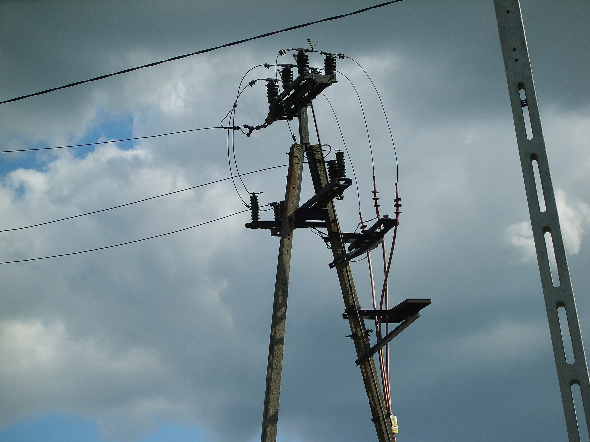
Picture the distribution feeder from the top down. Phase conductors sit on insulators at the pole top and on the crossarms. A neutral or secondary conductor rides lower on smaller units, and guy wires pass through strain insulators partway down. Each attachment point needs its own dielectric barrier, which is why a single pole can carry a dozen insulating units doing three or four different jobs.
That variety is the source of most specification confusion. The class divides by where and how the unit holds the conductor, not by shape alone. The sections below follow that logic, because the position decides the mechanical load, and the load decides the family.
The Double Job: Insulate and Support
Every unit on the structure does two jobs at once. Electrically, it keeps the energized conductor separated from the grounded pole, so current has no path to earth through the structure. Mechanically, it carries the conductor's weight plus ice, wind and line tension, and passes those forces into the pole through its pin, base or string hardware.
The way you size the part follows the harder of the two duties. A unit that insulates perfectly but snaps under an ice load fails the line, and one that holds forever but tracks with leakage current fails just as surely. Read the way you read any safety component: both ratings matter on every drawing, and neither substitutes for the other.
Both duties run for decades outdoors, which is why the failure modes deserve respect. Insulators are designed so the surface flashes over before the body punctures, because a flashover leaves the unit reusable while a puncture destroys it. When the flashover voltage can drop by more than half on a wet surface, the shape of the unit becomes as important as the material it is made from.
How the Leakage Path Stays Long and Dry
The working surface of any pole insulator is the path current would follow if it leaked from live metal to grounded metal. Designers stretch that path with ribs, called sheds or rain sheds, which increase the creepage distance from the energized wire to the mounting pin while keeping the inner surface dry. More shed edge means more dry distance between the conductor and the pole.
The sheds work like umbrellas over the surface below them, ensuring the part of the leakage path under each cup stays dry in wet weather. This matters because a wet film turns conductive, and the flashover voltage of a soaked unit can fall by more than half compared with its dry rating.
Creepage is quantified, not guessed. Minimum design values run about 20 to 25 mm per kV of line voltage, and the figure must increase where pollution or airborne sea salt coats the surface. The pole helps too. It is grounded with a heavy copper or copper-clad steel wire running down to earth, attached to the metal pin supporting each insulator. That wire gives leakage currents a controlled path instead of a wood-burning one.
Pin-Type Units Screwed to the Crossarm
The pin insulator is the oldest member of the class, developed earliest and still widely used in power networks up to 33 kV. The unit screws onto a threaded steel pin fixed in the crossarm or pole top. The conductor rests in a groove on the shell, and tie wire secures it against wind and vibration.
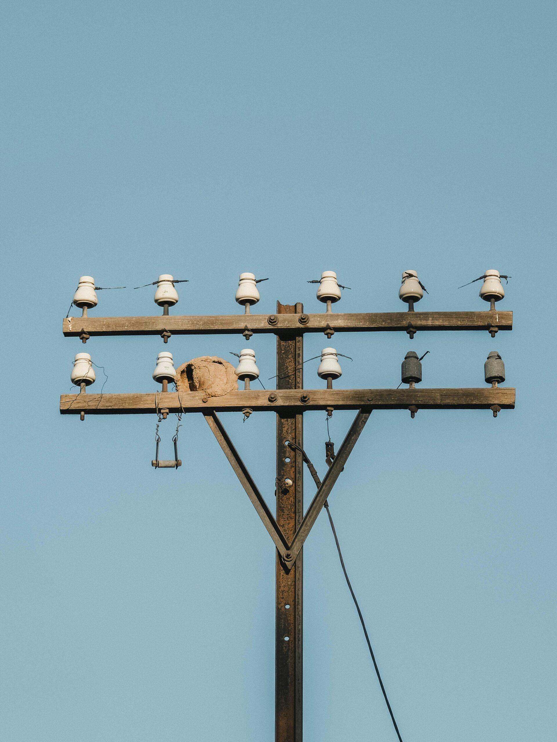
Higher classes strain the design. Pin-type builds intended for service between 33 kV and 69 kV tend to be bulky and have become uneconomical. The shell must grow to hold enough creepage while the threaded stem still carries a growing lever load. Distribution positions at or below 33 kV remain the natural home of the family.
Most distribution work still starts here, and the position-level details live in the site's guide to the cross-arm insulator, which covers the arm interface part by part. What matters at the pole level is simpler: pin units hold light-to-medium loads on straight and angle positions, and they end where the classes climb.
Post-Type Units Bolted to the Pole
The post insulator answers the pin's weakness with a different mount. Instead of a threaded stem, a bolted base clamps the unit to the arm or pole face. The cantilever bending load then passes through a rigid column rather than a screw thread. The style appeared in the 1930s as a more compact and rugged alternative. It rapidly replaced many pin-type units on lines up to 69 kV, with some configurations built for operation at up to 115 kV.
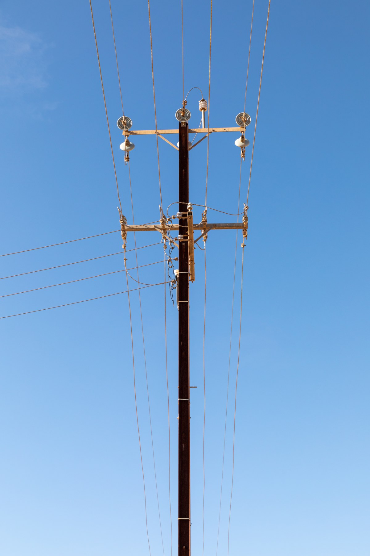
The rigid column also changes line behavior. A post holds the conductor at a fixed height and offset with no pivot, which suits narrow right-of-way builds and compact angle structures. Tops come in tie-top and clamp-top forms, so the conductor attachment still flexes to the line builder's preferred method.
On the hardware side, the pole-top pin deserves a mention beside the post. It is a taller stem that stands a pin-type shell above the pole top where no crossarm exists, a role the pole top insulator pin page covers in detail. The unit and the stem are separate line items, ordered together.
Suspension Strings Hung Below the Structure
Above 33 kV, the usual practice shifts to suspension insulators: glass or porcelain discs connected in series by metal links to form a string. The string hangs from the crossarm or pole top, with the conductor suspended at the bottom end. The number of disc units in the string depends on the voltage rating of the line.
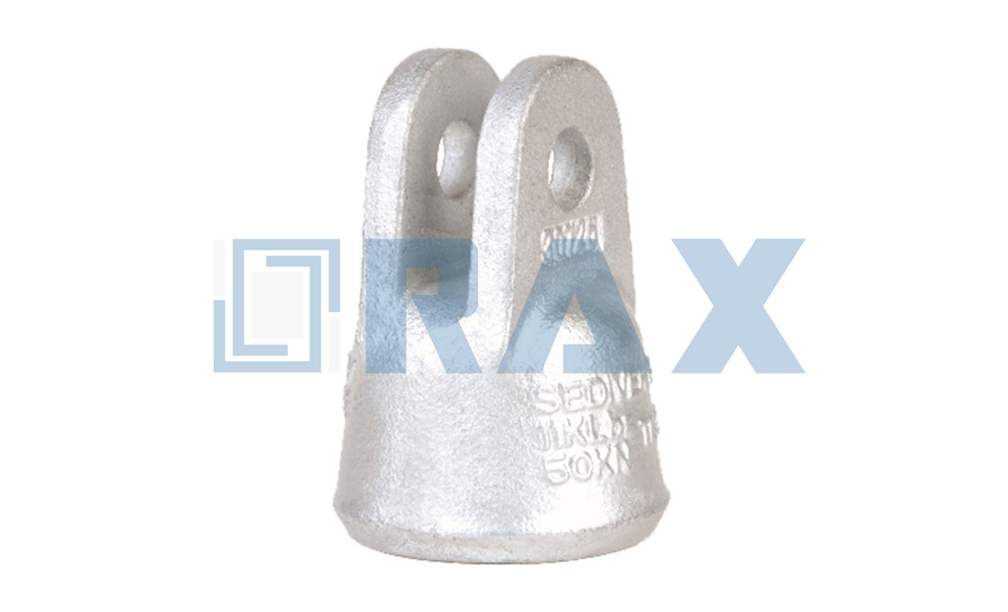
Each disc is a standardized building block, roughly 25 cm across, and a single unit supports a mechanical load in the range of 80 to 120 kilonewtons. Strings gain voltage capability by adding discs, which is why a 69 kV build and a 138 kV build can share the same hardware family with different counts. Cast caps and clevises are the metal links between those discs, rated in the same tensile class.
The hanging arrangement also relieves the structure of bending stress. Because the string pivots, the conductor pull stays close to pure tension along the string axis, and wind swing is absorbed as movement instead of leverage. Long spans and heavy conductors therefore end up on suspension positions almost by default.
Strain Duty at Dead-Ends and Corners
When the line terminates or turns sharply, the pole no longer merely supports the wire's weight. In our experience, dead-end positions are where underspecified insulator orders surface first. A dead-end must carry the lateral tension of every span it holds, and the pole insulator at that position is pulled in a straight line rather than compressed. Strain insulators answer that case, mounted in the line itself or in the guy wires that brace the pole.
A strain insulator must have considerable mechanical strength as well as the necessary electrical insulating properties, because it lives inside the tension path. Suspension strings can serve this duty when installed horizontally, while lower-voltage builds use compact strain or shackle styles, including the dead-end units common on secondary and service positions.
Porcelain, Glass and Polymer Compared for Pole Duty
Three materials dominate the class. Wet-process porcelain, glazed and fired, offers a dielectric strength of roughly 4 to 10 kV/mm and remains the standard body for pin and post shells. Glass provides a higher dielectric strength than porcelain, though it attracts condensation on the surface, so toughened glass lives mostly in suspension discs. Polymer builds pair a fiberglass rod with silicone rubber or EPDM sheds over metal end fittings.
| Property | Porcelain | Glass | Polymer |
|---|---|---|---|
| Typical pole role | Pin and post shells | Suspension discs | Pin, post and long-rod strings |
| Handling weight | Heavy | Heavy | Light |
| Contaminated service | Needs extra creepage | Needs extra creepage | Hydrophobic sheds help |
| Failure mode | Crack or flashover | Disc shatters, visible | Core or interface ageing |
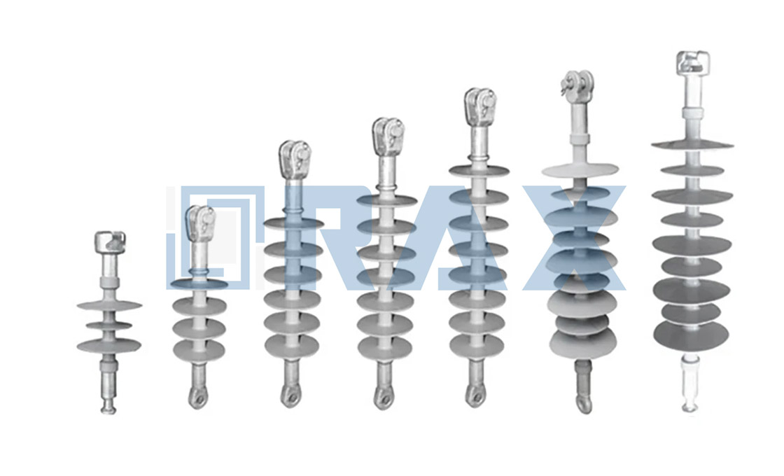
Polymer's hydrophobic silicone surface suits coastal and industrial air, and the weight saving matters to any crew that climbs with the units on a shoulder sling. The open limit is track record. These materials do not yet have the long-term proven service life of glass and porcelain. Buyers balance the handling and pollution gains against a shorter field history. For material-level depth, the site's polymer insulator guide carries the full treatment.
Matching the Unit to the Line Class
Voltage and position sort the whole pole insulator class. North American distribution lines typically carry voltages from 4.6 to 33 kV, which is exactly the band where pin shells and small posts live. As classes climb toward subtransmission, posts take the straight positions and suspension strings take the heavy spans, while strain units hold every dead-end regardless of class.
Environment narrows the choice further. Contaminated air pushes the creepage figure up and favors silicone sheds. Mountain routes favor the pivot of hanging strings, and tight urban builds favor rigid posts that hold conductors at fixed offsets. The insulator line covering overhead line insulators and the matching insulator fittings are organized along the same position logic used in this guide.
The Short Version for Field Crews
- A pole insulator is the dielectric barrier at every attachment point, doing one electrical job and one mechanical job at once.
- Pin units serve up to about 33 kV, posts replace them toward 69-115 kV, suspension strings carry the higher classes, strain units hold dead-ends.
- Sheds stretch the creepage path; budget roughly 20-25 mm per kV, more where pollution or salt settles.
- RaxPower supplies the units and the pins, posts and fittings they mount on, matched to each position.
Frequently Asked Questions
What does a pole insulator actually do?
It holds an energized conductor clear of the grounded pole and carries the conductor's weight, ice and wind loads into the structure. Insulation and mechanical support always come as one package.
Which types are used on a utility pole?
Pin insulators on crossarm pins, post insulators bolted to arms or pole tops, suspension strings hung below the structure, and strain units at dead-ends and corners. Spool units handle secondary and neutral positions.
Why do these units have ribbed skirts?
The sheds act as umbrellas that keep part of the leakage path dry and lengthen the creepage distance from live metal to grounded metal. Extra creepage is budgeted at roughly 20-25 mm per kV.
How far up in voltage can a pin-type unit go?
Pin construction stays common in networks up to 33 kV. Designs for the 33-69 kV band turn bulky and uneconomical, which is where bolted line posts take over the straight positions.
Which material suits a coastal or polluted line?
Silicone rubber sheds stay hydrophobic where sea salt and industrial film settle, cutting leakage risk. Porcelain remains dependable with extra creepage, and glass discs suit the higher suspension positions.