
Until a line study puts numbers on it, the 33 kV ceiling on pin insulators sounds like grid folklore. It is really the point where two scaling laws cross. One is the leakage path a voltage class demands; the other is the bending moment a taller body must survive on a short stub of galvanized steel. Both laws work against the pin at the same time, and neither cares how good the porcelain is.
Our order desk sees the same split inside RFQ data: pin-type inquiries run steadily through 33 kV-class work, then stop. From 66 kV upward, the same projects ask for line posts and string hardware by name. That buying pattern is the pin insulator voltage limit showing up in procurement rather than in a textbook. The arithmetic behind it decides where a pole-top budget should go, so it is worth walking through in full.
Where the 33 kV Ceiling Actually Comes From
Reference books agree on the neighborhood even when they disagree on the exact boundary. One standard reference states that "The pin insulator is used in power distribution for the voltage up to 33kV". The same source hedges by pinning the limit "above 66kV", where "the suspension insulators are used for high voltage work". A boundary that drifts between 33 and 66 kV is not a clause in a testing standard. It is an economics crossover, and crossovers have causes you can measure.
The causes are the two scaling laws. Electrically, the surface that flashes over must get longer roughly in proportion to the class voltage. Mechanically, the moment at the pin grows as the body gets taller, as if the body were a longer wrench on the same bolt. The pin insulator voltage limit is simply where both curves hit catalog limits at once. Both catalogs are public, so the crossing can be read straight off published data sheets.
Leakage Distance Grows With Every Voltage Step
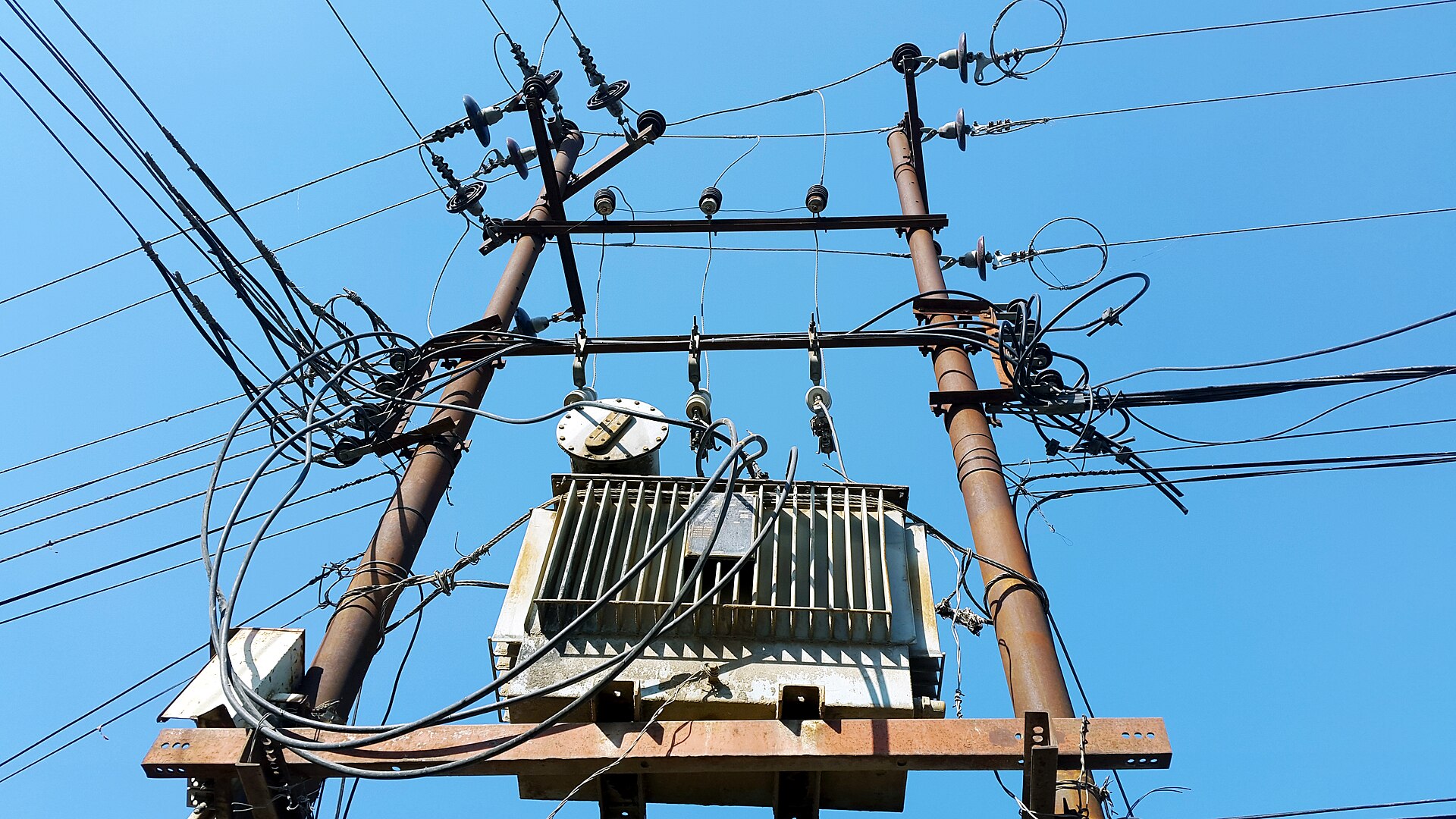
Flashover starts on the surface. Rain and pollution build a conductive film, the film bridges toward the grounded pin, and the arc follows. Designers fight back with geometry: "The length of the leakage path is made large by constructing several layers called petticoats or rain sheds". Each added skirt extends the wet path and keeps part of the surface dry, so the same body can stand off more voltage.
How much surface a class demands is quantified in the pollution literature. INMR summarizes the legacy recommendation "namely 16, 20, 25 and 31 mm/kV(U m ) respectively for Light, Medium, Heavy and Very Heavy pollution environments". Read that as a price list: every kilovolt of system voltage buys another 16 to 31 millimetres of sheds. Doubling the class roughly doubles the body the pin must carry.
Real catalogs confirm the proportionality. The table below lists four actual units from pin class to transmission class, and the right-hand column is the leakage divided by the class voltage.
| Equipment class | Hardware type | Leakage distance | Leakage per class kV |
|---|---|---|---|
| 7.2 kV | ANSI 55-2 porcelain pin unit | 127 mm | 17.6 mm |
| 24 kV | composite line post | 480 mm | 20.0 mm |
| 36 kV | composite post, double flange | 675 mm | 18.8 mm |
| 72.5 kV | composite station post | 1813 mm | 25.0 mm |
Every quotient lands inside the 16 to 31 mm/kV band quoted above, which is exactly what proportionality predicts. This is the electrical half of the pin insulator voltage limit: raise the class and the sheds must multiply on one rigid body. At 66 kV-class duty the shell would need twice the creepage of a 33 kV build, before any mechanical question is asked.
The wet numbers tell the same story from another angle, and the two catalogs grade it differently. The 7.2 kV pin unit flashes over at 25 kV wet across an 86 mm dry arc, about 0.29 kV per millimetre of wet-flashover gradient. The 36 kV post is specified to withstand 70 kV wet across a 235 mm dry arc, about 0.30 kV per millimetre of wet-withstand gradient. Wet flashover for the pin and wet withstand for the post are different severity measures, yet both land near 0.3 kV per millimetre of dry arc. Either way, a class that doubles the kilovolts doubles the millimetres first.
The ANSI Pin Ladder Shows the Squeeze
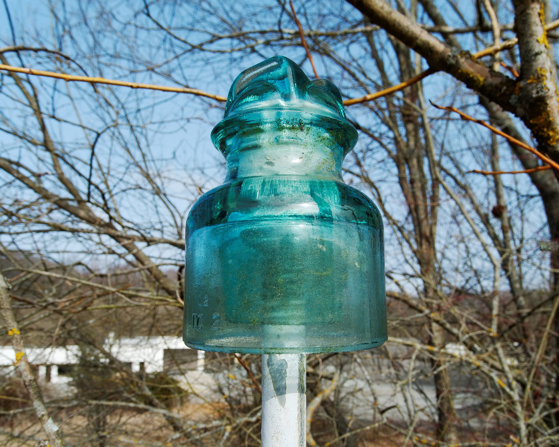
The ANSI 55-x ladder makes the growth visible step by step. The porcelain catalog tabulates them plainly: "102 57 102 127 86 102 178 114 127 229 127 127 305 159 152 Cantilever strength (KN) 13 11 11 13 13". Sorted into rows, the ladder reads like this.
| ANSI class | Leakage (mm) | Body height (mm) | Wet flashover (kV) | Cantilever (kN) |
|---|---|---|---|---|
| 55-1 | 102 | 102 | 20 | 13 |
| 55-3 | 178 | 127 | 30 | 11 |
| 55-5 | 305 | 152 | 45 | 13 |
Three columns tell one story: from class 55-1 to 55-5 the leakage distance triples, wet flashover more than doubles, and body height climbs about half as fast again. The mass grows with the porcelain. The same catalog lists "0.5 60 0.65 40 1 30 1.55 16 2.75 12" across the ladder, from half a kilogram to 2.75 kilograms per body. The ANSI ladder turns the pin insulator voltage limit into millimetres and grams, one cemented shell at a time. Across a feeder with hundreds of pole tops, those kilograms compound fast.
Cantilever Strength Stays Flat as Bodies Grow
Mechanically, every pin insulator lives in bending. The rating itself says so: Hubbell lists its ANSI 55-2 unit with "Cantilever Bending Strength - Max. 2500", manufactured "according to ANSI C29.5", which for this family is a 2,500 lb ceiling, about 11 kilonewtons. The independent catalog ladder above agrees, showing 11 to 13 kN across every class. That cap has barely moved across the whole family.
Now put the two tables side by side. The strength column stays pinned near 11 to 13 kN while body height climbs from 102 to 152 mm, and taller builds beyond the ladder push further still. Bending moment is tie-point force times lever length, and the lever is the body itself, so the same conductor load bites harder on every taller class. This is the mechanical half of the pin insulator voltage limit: margin melts from both ends at once. For scale, the whole 55-2 body above the seat is just 1.6 lb of porcelain, so the lever, not the mass, is what limits it.
Geometry fixes where that moment concentrates. The tie sits in the top groove, and the fulcrum is the C-neck seat on its 1-inch pin hole. The porcelain between them works like a lever on a short fulcrum. Wide the sheds may be; tall the body must be. Every millimetre between groove and seat is an extra arm for the same conductor pull.
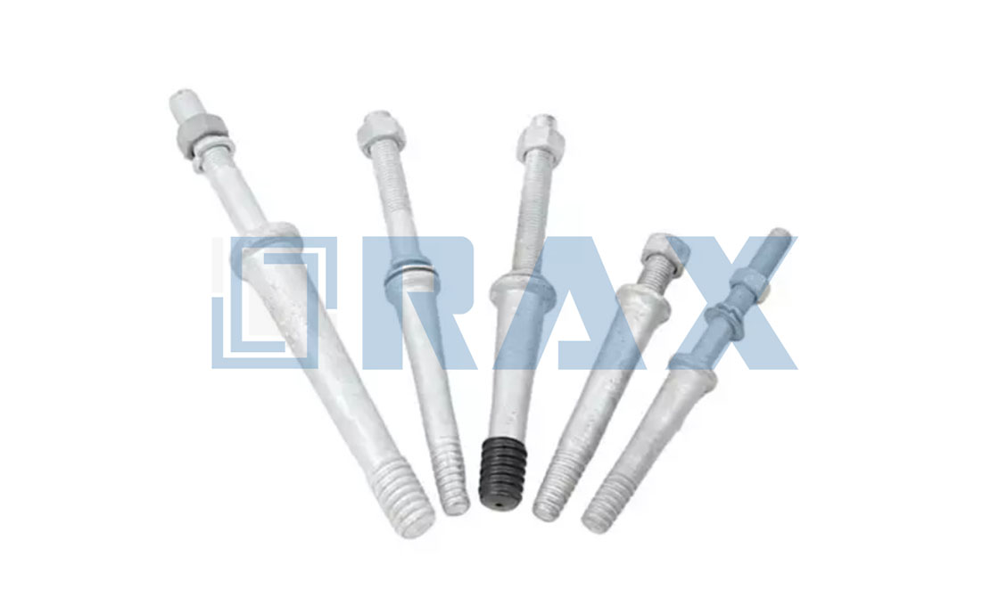
The hidden victim is the steel under the porcelain. The spindle takes the whole moment into the cross-arm through a threaded joint, and catalogs flag the wear mode bluntly: "The pin of the insulator damaged the insulator thread". Keeping that joint honest is routine work for the support hardware crew, and it gets no easier as bodies grow.
Span Tension Multiplies the Pin's Problem
So far the conductor has only been a weight at the tie point. It also pulls. Line design gives the horizontal tension through the sag relation. One engineering summary defines it: "mid-span sag equals the weight per unit length multiplied by the span squared, divided by eight times the horizontal tension". Rearranged, tension equals weight times span squared over eight times sag, so tension climbs with the square of span length at a fixed sag.
When a utility uprates a route, spans lengthen and conductors thicken, so the tie-point load climbs steeply at exactly the moment the taller leakage body lengthens the lever. A force that doubles against a lever that grows by half leaves the bending moment roughly tripled, against a pin strength class that has not moved. Double the span at the same sag and the horizontal tension quadruples, by pure arithmetic on that formula. The pin insulator voltage limit, in one sentence: the body must grow with the voltage while its anchoring stub cannot.
Matching pin, post, and string hardware to a voltage class is catalog arithmetic. Send us your class, span, and pollution zone, and the arithmetic comes back with the drawing.
Why Line Posts Win Above the Pin Band
The line post answers the mechanical half first. It stands the conductor on a stiff column instead of a threaded stub, and its strength does not shrink as the body grows. An Ensto 24 kV post carries a "Specified mechanical load: 15 kN", and the 36 kV double-flange post holds a "Specified Cantilever Load (SCL): 16 kN". The same maker's 72.5 kV station post still lists "SCL: 16kN" at 770 mm of height. Sixteen kilonewtons at any class is the headline the pin family cannot match.
The electrical duty scales without apology on the same hardware. The 24 kV post is rated above 125 kV lightning impulse and 50 kV wet withstand. The 36 kV post takes 70 kV wet withstand across a 235 mm dry arc. The 72.5 kV post carries 1813 mm of creepage on a 682 mm arc. Compare those columns with the pin ladder and the crossover stops being mysterious.
The paperwork shows the same upgrade. The 36 kV post ships with a specified tensile load of 6.4 kN and a 10 kN routine test load, numbers a pin data sheet simply does not offer. A part that publishes both a cantilever and a tensile rating is built for positions the pin was never asked to hold.
Above the post band, suspension strings change the economics by repeating a standardized disc instead of growing a monolith. That is the same move the textbook made when it retired the pin "for high voltage work". That crossover, not a decree, is what sets the pin insulator voltage limit near 33 kV.
Where Engineers Still Specify Pins Today
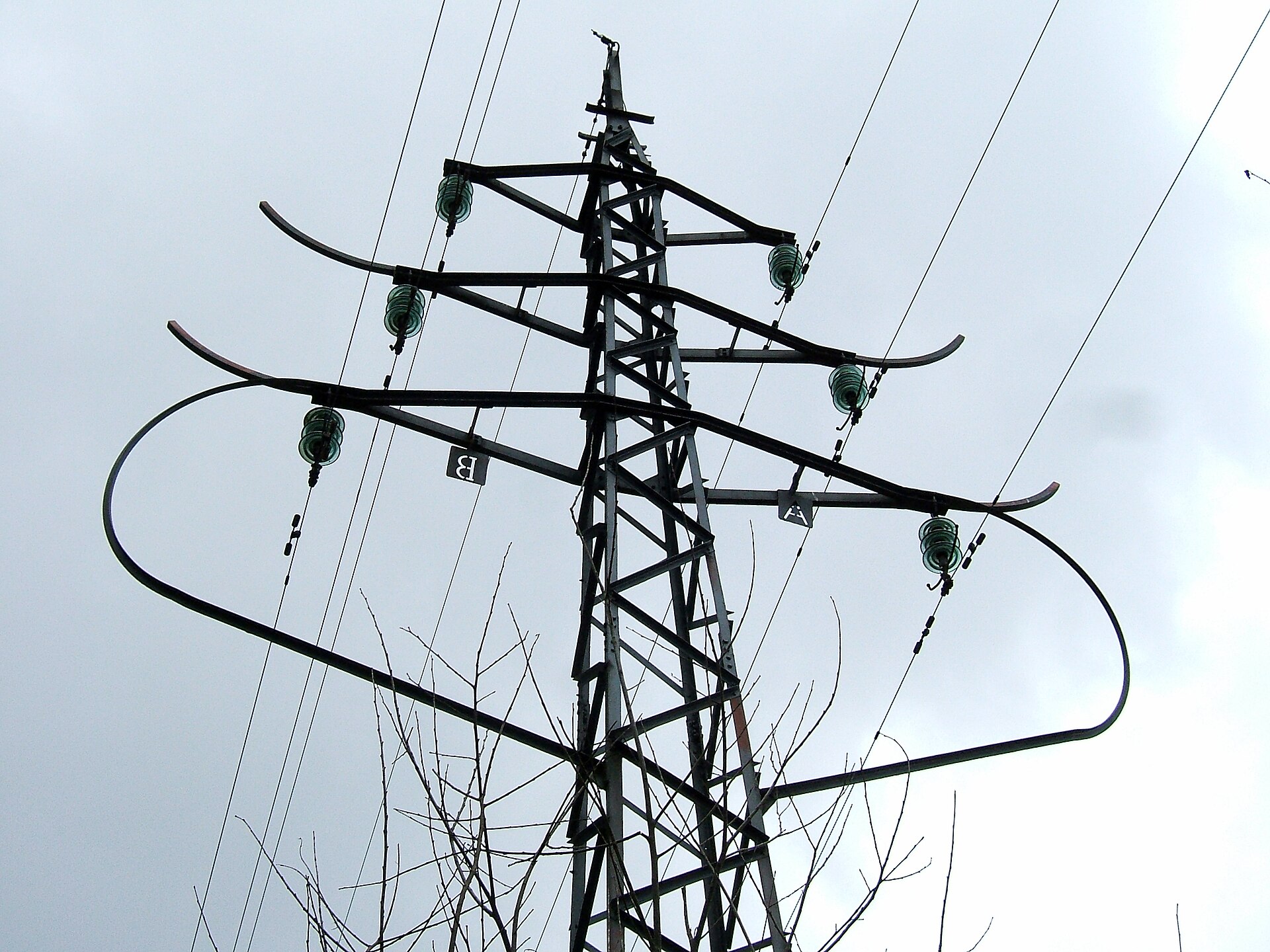
Inside its band the pin remains the cheapest pole top in the catalog: one fitting, one tie, minutes of bucket-truck time. In our experience, that installation speed is why 11 to 33 kV feeders keep specifying them. Molding sheds onto one composite blank replaces the old stack-and-cement step while keeping the same tie-top speed. As one catalog puts it, "For low voltage, the single piece pin insulator is used, and for high voltage two or more pieces are cemented together". Cementing is where the cost curve starts to bend.
If you are mapping the family, start with the anatomy explainer, then take the selection questions to the composite choosing guide. The pin versus polymer comparison and the cross-arm positions guide cover the rest of the pole top.
Frequently Asked Questions
What is the pin insulator voltage limit?
Near the 33 kV class. Leakage demand grows with every voltage step while the pin's bending strength stays near 11 to 13 kN, so margin runs out together on the electrical and mechanical side.
Could a taller pin body push the ceiling higher?
Only a little. Extra height buys leakage distance, but it lengthens the bending lever, so the moment at the pin thread grows with every millimetre gained. The strength cap does not move with it.
Why do older textbooks mention 66 kV for pins?
Because the boundary is an economics crossover, not a standard clause. One reference limits pin use above 66 kV by size, weight and cost, while catalog practice already stops pin bodies near the 36 kV class.
What replaces a pin insulator above 33 kV?
Line posts first: a 36 kV post carries a 16 kN cantilever rating with 675 mm of leakage. Higher classes go to suspension strings, which stack standardized discs to reach any voltage.
Does the tie wire affect the voltage ceiling?
No. Binding wire secures the conductor and is renewed as a wear item on patrol rounds. The ceiling comes from leakage geometry and cantilever arithmetic, which no tie pattern can change.