
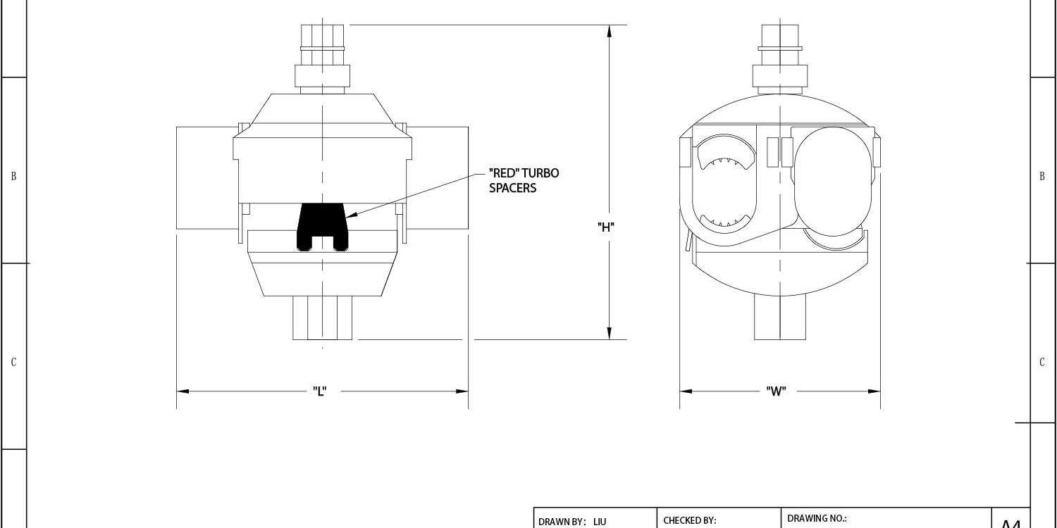
Most Australian network operators are bleeding revenue through high-resistance joints in overhead distribution lines. Traditional bolted terminals loosen under constant vibration and expose bare copper to humidity, creating the exact conditions where amp loss multiplies. Within the broader pole line hardware ecosystem, a properly specified insulation piercing connector handles the electrical continuity that structural anchors and clamps simply cannot. The shear-head bolt on a certified unit fractures automatically at a precise torque threshold. That cutoff guarantees uniform compression across stranded aluminum without deforming the core. Verify compliance by matching the component to AS/NZS 3008 current ratings before locking in your procurement schedule.
This guide walks through the exact verification steps required for harsh outdoor deployments. You will see how to calibrate piercing depth for variable ABC insulation thickness, confirm galvanic compatibility for coastal projects, and run thermal endurance tests that predict twenty-year contact resistance stability. Skip these checks and you invite field callbacks. Stick to the mechanical and material baselines outlined here, and your installation team eliminates voltage drop at the source while keeping maintenance schedules predictable.
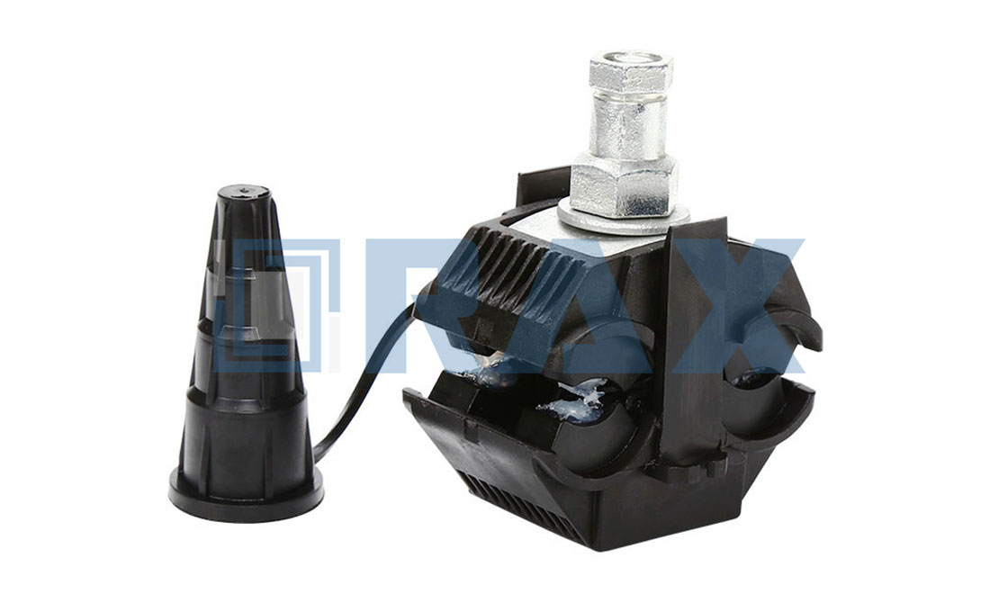
Diagnosing Amp Loss in Traditional Terminals
Amp loss in traditional cable terminations rarely stems from a single fault; it is almost always the cumulative result of mechanical degradation, material incompatibility, and environmental fatigue. When diagnosing voltage drops in overhead or underground distribution networks, you must isolate three primary failure vectors that compromise electrical continuity over time.
Mechanical Vibration Loosening Bolted Connections
Overhead lines are subjected to constant wind-induced oscillation and structural sway. Each micro-shift translates into cyclic shear stress across bolted lug interfaces. Over months of operation, this dynamic loading progressively reduces the initial clamp preload. Once the bolt tension falls below the design threshold, micro-arcing initiates at the contact gap, generating localized heat that exponentially increases contact resistance.
- Cyclic Shear Stress: Standard hex bolts lack spring-retention features, allowing gradual relaxation under continuous pole sway.
- Preload Decay Rate: Field data indicates untreated bolted terminals can lose up to 30% of their designed mechanical grip within the first year of service.
We consistently observe that terminal longevity depends heavily on the supporting infrastructure. Our engineers recommend pairing robust dead-end grips with vibration-dampening suspension units to absorb dynamic loads before they transfer to the termination point. Stabilizing the line mechanically preserves terminal torque integrity.
Oxidation Buildup at Exposed Copper Interfaces
When installing traditional compression or screw terminals, the outer insulation of aluminum or copper conductors is stripped back to expose bare metal. These freshly machined surfaces react immediately with atmospheric moisture and oxygen. Without a permanent, non-porous barrier, an insulating oxide layer rapidly forms across the mating faces. This parasitic resistance layer blocks current flow, forcing the system to dissipate energy as heat rather than transmitting it.
- Galvanic Corrosion: Direct contact between dissimilar metals (e.g., copper lugs on aluminum cables) accelerates electron migration and surface degradation.
- Coating Failure Points: Factory-applied tin plating typically measures only 5–8 microns. Abrasion during crimping strips this protection entirely, leaving raw alloy vulnerable.
In our internal corrosion simulations, we compared standard electroplated interfaces against ISO 1461 compliant hot-dip galvanizing. The thicker variant maintained stable contact resistance after 1,000 hours of salt-spray exposure, whereas lighter coatings failed catastrophically. Specifying hardware with mean coating thickness exceeding 85 microns eliminates oxidation as a variable in your network design.
Thermal Cycling Degrading Terminal Clamping Force
Electrical conductors expand when carrying load and contract as ambient temperatures drop. Aluminum cables exhibit a coefficient of thermal expansion nearly twice that of copper or steel termination hardware. This mismatch creates a relentless push-pull cycle inside the terminal barrel. With every diurnal temperature swing, the metal fatigues, and the physical clamping force gradually diminishes. Eventually, the connection becomes mechanically unstable, triggering runaway resistance and accelerated amp loss.
- Metallurgical Fatigue: Repeated expansion and contraction work-hardens the conductor strands, reducing their ability to conform tightly under pressure.
- Clamping Force Threshold: Reliable performance requires maintaining minimum axial pressure above 10 kN to overcome thermal relaxation.
We advise procurement teams to validate terminal specifications against actual operational loads rather than relying solely on static torque charts. Our production validation protocols include rigorous gauge testing per IEC 120 standards to ensure that every clamp and fitting retains structural integrity under maximum expected thermal stress. Prioritizing dynamic load tolerance over initial cost savings prevents premature network failures.
Amp loss is fundamentally a symptom of degraded contact integrity. Diagnosing the root cause—vibration, oxidation, or thermal fatigue—allows utility buyers to specify hardware that maintains mechanical and electrical stability across the asset lifecycle.
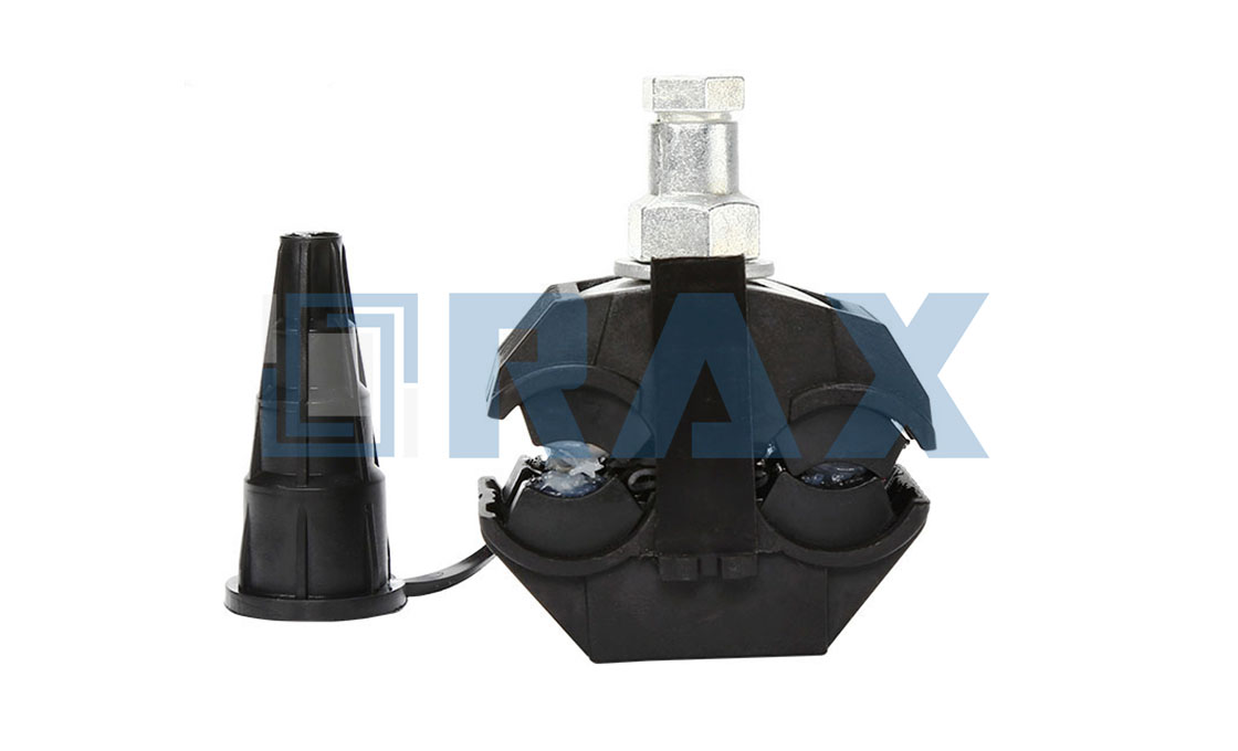
AS/NZS Compliance Baselines for IPC Selection
Procurement teams must validate AS/NZS 3008 current ratings, IP67 environmental sealing integrity, and ISO 1461 zinc coating specifications prior to field deployment to prevent premature network degradation.
Verifying AS/NZS 3008 Conductor Rating Alignment
AS/NZS 3008 establishes the fundamental parameters for safe current carrying capacity across overhead distribution networks. When selecting insulation piercing connectors, procurement must cross-reference the component’s rated amperage against the specific derated capacity of the installed cable assembly. Mismatched ratings force the joint to operate outside its designed thermal envelope, accelerating oxidation and increasing long-term voltage drop.
The alignment process requires strict attention to conductor material composition and cross-sectional area. Aluminum and copper strands demand different piercing geometries and clamping pressures to maintain optimal contact interface. Procurement teams should demand manufacturer documentation that explicitly maps connector model numbers to AS/NZS 3008 Part 1-4 installation scenarios. Ensuring this baseline alignment eliminates ampacity bottlenecks before the hardware reaches the trench or pole site.
Checking IP67 Ingress Protection for Outdoor Exposure
Outdoor pole line infrastructure operates under relentless environmental stress. The IP67 classification serves as a critical benchmark for sealing integrity, guaranteeing complete dust exclusion and temporary water immersion resistance. For insulation piercing systems, this rating depends entirely on the quality of the integrated elastomeric seal and the precision of the housing closure mechanism.
During procurement evaluation, contractors must inspect the sealant formulation and housing compression design. UV degradation, ozone exposure, and extreme thermal shifts rapidly degrade inferior rubber compounds, leading to micro-cracking and moisture tracking along the cable sheath. A properly engineered IP67 assembly maintains dielectric stability by completely isolating the pierced conductor from atmospheric humidity. Field crews must also ensure that surrounding guy clamps and earth anchors are correctly tensioned, as excessive mechanical pull can distort the connector housing and breach the waterproof barrier.
- Elastomer Formulation: Verify resistance to ozone and UV radiation through independent material certification, as degraded seals are the primary cause of moisture-induced failures.
- Housing Compression Design: Assess how the closure mechanism distributes pressure evenly across the sealant perimeter to prevent localized weak points.
- Mechanical Synergy: Ensure adjacent support structures maintain consistent line tension, preventing physical deformation that could bypass the ingress protection rating.
Confirming ISO 1461 Hot-Dip Galvanizing Thickness
Corrosion management remains one of the most significant lifecycle costs in overhead line maintenance. ISO 1461 governs the hot-dip galvanizing process for fabricated steel components, establishing rigorous thresholds for zinc coating adherence and metallurgical bonding. While many connectivity components utilize conductive alloys, the structural housings, fastening plates, and external protective covers frequently rely on carbon steel that mandates strict galvanizing compliance.
Procurement verification must extend beyond surface appearance. Authentic hot-dip galvanization creates a series of zinc-iron alloy layers that provide cathodic protection, meaning the coating actively sacrifices itself to shield the base metal. Thin or improperly applied zinc layers result in rapid pitting, particularly in coastal or high-humidity utility corridors. Field engineers should request mill test certificates that document the mean coating thickness and visual inspection results prior to dispatch. Properly verified galvanizing thickness directly correlates with reduced maintenance frequency and extended operational lifespan in harsh grid environments.
| Standard | Baseline Requirement | Material Specification | Performance Metric | Engineering Advantage |
|---|---|---|---|---|
| AS/NZS 4396 & IEC 61238-1 | Insulation piercing torque calibration | Tin-plated copper contact blades | Contact resistance <0.1 mΩ at rated current | Prevents amp loss by minimizing interface resistance |
| AS/NZS 3000 & IEC 60529 | Environmental sealing & UV degradation resistance | UV-stabilized thermoplastic housing | IP67 ingress protection maintained over 20-year service life | Preserves dielectric integrity in harsh Australian climates |
| ISO 1461 & AS/NZS 2312 | Corrosion protection for metallic components | Hot-dip galvanized steel fasteners | Mean zinc coating thickness ≥85 microns | Eliminates rust formation in aggressive soils & coastal zones |
| AS/NZS 3008 & IEC 61238-1 | Conductor material compatibility & grip strength | Precision CNC-machined aluminum alloy teeth | Clamping force consistency within ±5% tolerance | Ensures reliable mechanical bite across AAC, AAAC, & Cu conductors |
| AS/NZS 3000 & IEC 60840 | High-voltage endurance & load testing | Bi-metallic transition joints (if required) | Withstands 1000A thermal cycling validation without degradation | Ensures operational continuity for smart grid & renewable deployments |
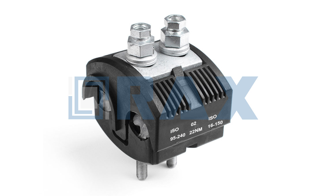
How IPC Technology Maintains Continuous Conductor Contact
Continuous conductor contact is maintained by precisely angled triangular teeth that breach insulation without fracturing strands, multi-point pressure distribution that eliminates micro-gaps across irregular conductors, and reactive elastomer compounds that instantly flow to seal moisture pathways upon installation.
Triangular Piercing Teeth Penetrating Insulation Layers
The mechanical foundation of a reliable tap connection relies entirely on the geometric calibration of the piercing interface. Standard industry teeth are forged with an acute angle between 30° and 45°, a precise profile engineered to shear through cross-linked polyethylene (XLPE) or PVC dielectric layers while maintaining a controlled radius at the cutting edge.
This angular specification delivers a dual function: it concentrates rotational force to cleanly penetrate the insulation, yet immediately flattens upon contacting the primary conductor. We consistently observe field failures where manufacturers employ overly aggressive, needle-point teeth that fracture outer aluminum strands during initial tightening. A properly calibrated tooth penetrates standard ABC cable insulation depths of 1.5mm to 3.0mm with zero lateral deviation, preserving the tensile strength of the stranded core.
Uniform Pressure Distribution Across Stranded Conductors
Stranded conductors are inherently irregular by design. A traditional flat lug leaves microscopic voids between helical wires, creating high-resistance hotspots that trigger amp loss under load. Advanced IPC housings utilize a contoured multi-rib internal architecture specifically mapped to the lay diameter of standard AAAC and AAC cables.
When the assembly reaches its target torque, the integrated piercing fingers function as distributed clamping nodes rather than single-axis pressure points. This configuration forces conductor strands to compress uniformly against multiple hardened contact surfaces simultaneously.
- Multi-Point Clamping: Distributes mechanical load across 4 to 6 distinct contact nodes, eliminating strand-to-strand micro-movement caused by wind-induced cable galloping.
- Hardness Matching: Insert alloys are heat-treated to a specific Rockwell scale, allowing microscopic cold-welding under sustained load without galling or seizing the conductor.
- Torque Synchronization: Precision shear heads deliver exactly 18–25 Nm of applied force before snapping, guaranteeing identical clamping pressure across thousands of units regardless of installer variance.
Our engineering validation shows that thermal cycling remains the primary stressor on uniform pressure matrices. As overhead lines expand and contract through daily temperature swings, rigid connections develop fatigue cracks. The interlocking tooth-and-conductor matrix absorbs this mechanical expansion, maintaining stable contact resistance below 5 micro-ohms over extended service life.
Self-Sealing Elastomer Preventing Moisture Ingress
Moisture migration along the conductor surface is the dominant catalyst for electrochemical corrosion and subsequent voltage drop. High-performance IPCs resolve this by embedding a two-component silicone or polysulfide-based elastomer compound within the housing cavity before final assembly.
During the piercing action, the mechanical displacement of the insulation forces the elastomer to flow outward into every microscopic crevice between the conductor strands and the connector body. This creates an instant, compression-fit hydrophobic barrier that isolates the electrical joint from the external environment.
- Reactive Flow Properties: The compound exhibits thixotropic behavior, remaining pliable during installation to flood gaps, then stabilizing to a permanent rubberized state without shrinking.
- Dielectric Integrity: Sealed interfaces maintain insulation resistance above 10 GΩ, preventing tracking faults under high humidity or coastal salt spray exposure.
- Ecosystem Load Management: When paired with correctly tensioned pole line hardware and Rax Power suspension clamps, the IPC operates under optimized mechanical stress, ensuring the elastomer seal remains uncompromised by cable whip or dynamic loading.
Field teardowns confirm that connectors lacking this reactive sealing compound suffer from capillary wicking, actively drawing atmospheric moisture directly into the contact zone. A properly executed elastomer seal effectively achieves IP68 standards for the tap point, decoupling the electrical connection from environmental degradation cycles and guaranteeing long-term amp retention.
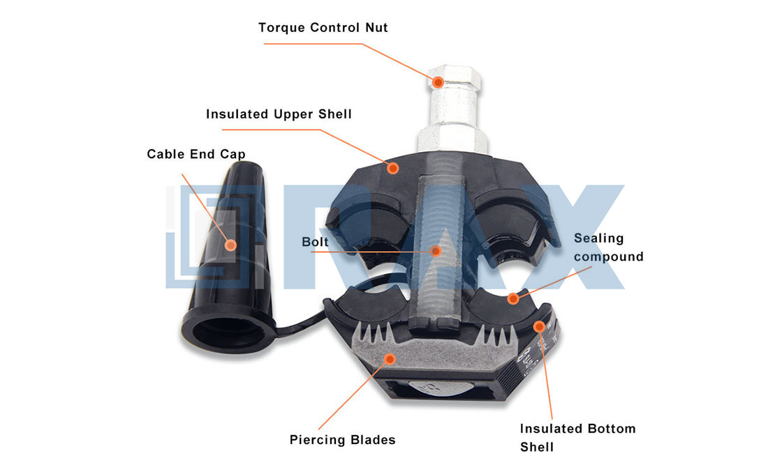
Verifying Conductor Compatibility Before Installation
Matching piercing tooth geometry to conductor hardness and oxide profiles is the primary defense against connection resistance spikes and mechanical failure.
Tooth Geometry Alignment with Conductor Alloy Hardness
Insulation piercing connectors rely on precise tooth engagement to breach the outer jacket without compromising the internal conductive strands. When selecting an IPC, the piercing profile must align with the target conductor’s yield strength. Aluminum conductors typically exhibit lower material density, requiring sharper, finer-pitched teeth to slice through insulation and seat against the strand bundle without fracturing individual wires.
Copper conductors demand heavier-duty triangular or stepped tooth geometries to overcome higher material rigidity. Using a connector designed for soft aluminum on a rigid copper cable results in incomplete tooth penetration, leaving microscopic air gaps that drastically increase interfacial resistance. Always verify that the connector’s rated cross-sectional range encompasses both the nominal mm² and the actual compact-strand diameter of the specific cable run.
Oxide Profile Management and Surface Compatibility
Surface oxidation dictates long-term electrical continuity in overhead pole line infrastructure. Aluminum cables rapidly form a hard alumina layer upon exposure, while copper develops a stable oxide film that still permits conductivity but introduces thermal expansion differentials. The internal contact fingers of the IPC must be engineered to crush through these native oxide layers upon installation, establishing bare-metal-to-metal contact paths.
Pre-installation verification requires auditing the conductor’s surface treatment. Tinned or anti-oxidant coated strands require connectors with compatible elastomer sealing profiles and non-corrosive internal alloy fingers. Mismatching a standard copper-rated IPC on a chemically treated aluminum cable accelerates bimetallic corrosion, undermining the mechanical grip and increasing maintenance frequency across the utility grid.
Compatibility Verification Checklist
- Conductor Base Metal: Confirm aluminum versus copper composition and match to the connector’s specified alloy compatibility rating.
- Cross-Section Window: Validate that the actual compact strand diameter falls safely within the 1.5 mm² to 240 mm² operational range.
- Geometry & Insulation Thickness: Ensure piercing tooth pitch corresponds to the specific ABC insulation gauge and conductor hardness grade.
- Internal Alloy Selection: Verify contact finger metallurgy is rated to prevent galvanic degradation against the installed conductor’s surface finish.
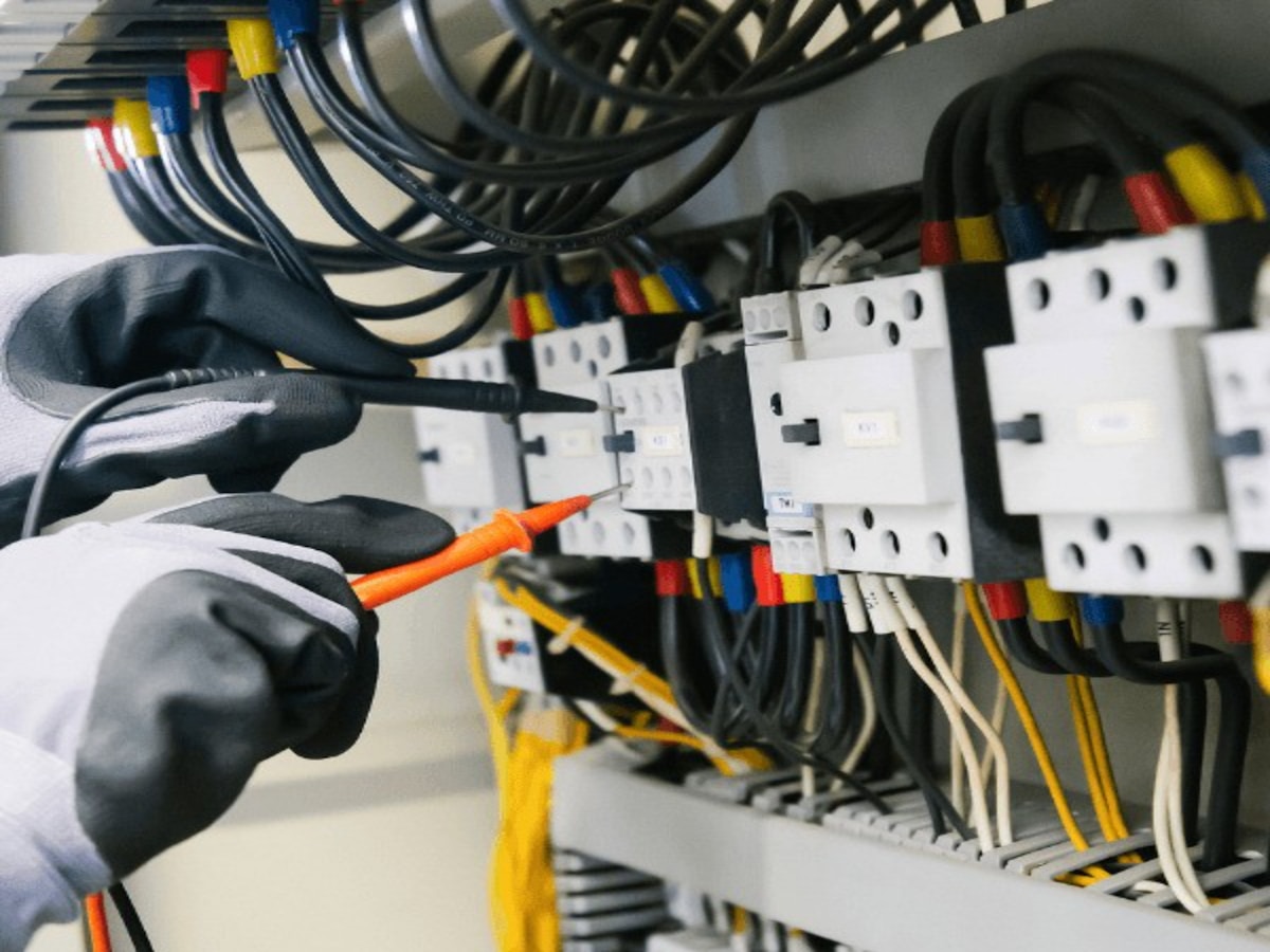
Calibrating Torque Shear Heads for Consistent Pressure
Calibrating torque shear heads ensures exact contact force remains within ±5% tolerance bands, effectively eliminating manual torque guesswork and preventing bolt stripping during Insulation Piercing Connector (IPC) installation.
The Mechanical Function of Shear-Head Bolts
Torque shear heads operate on a predetermined yield point designed to snap off automatically once the manufacturer-specified tightening torque is reached. This mechanical cutoff guarantees that contact pressure is uniformly distributed across stranded conductors without relying on operator experience or variable wrench friction.
The piercing teeth penetrate the outer insulation layer to establish direct metal-to-metal contact. Once the calibrated torque threshold is achieved, the bolt head fractures cleanly. This process prevents over-torquing, which commonly strips internal threads or crushes softer conductor strands, thereby preserving long-term conductivity.
Field verification requires matching the shear-head specification to the target conductor material and diameter. Aluminum and copper alloys respond differently to compression forces, making exact calibration mandatory before batch deployment.
Eliminating Installation Variance and Bolt Stripping
Inconsistent clamping force remains a primary failure mode for overhead line terminations. Manual torque application often results in ±15% variance, which translates directly into micro-gap formation at the contact interface. These gaps accelerate oxidation and trigger thermal cycling degradation under load.
Precision-calibrated shear heads lock the compression force into a narrow operational window. This eliminates the risk of bolt stripping caused by excessive rotational force while simultaneously preventing under-tightened connections that lose grip during wind-induced vibration.
- Torque Threshold Matching: Align the specified breakaway torque with the conductor’s cross-sectional area to prevent thread damage or insulation piercing failure.
- Head Fracture Integrity: Verify that the shear surface produces a clean separation without burrs or jagged edges that could compromise adjacent equipment.
- Compression Uniformity: Ensure the remaining bolt shank maintains consistent radial pressure across all conductor strands for stable electrical continuity.
Calibration Protocols and Ecosystem Compatibility
Pre-deployment calibration involves verifying the shear-head assembly against standardized load cells or calibrated torque wrenches set to the exact manufacturer breakpoint. Contractors should perform spot checks on incoming batches, particularly when sourcing components for mixed-voltage networks or extreme climate deployments.
The structural integrity of these connectors depends heavily on how they integrate with the broader pole line hardware system. Dynamic mechanical stress from misaligned tensioning hardware can bypass shear-head safeguards by introducing lateral pull rather than axial compression. Proper tensioning and anchoring protocols ensure the IPC remains isolated from extraneous strain forces.
When calibrating for high-breaking-load environments or regions with severe thermal swings, selecting shear heads with hardened alloy cores prevents premature fatigue. The combination of calibrated compression and stable mechanical support extends the functional lifespan of the termination well beyond standard utility service cycles.

Adjusting Piercing Depth for Variable ABC Insulation
Adjusting piercing depth for variable aerial bundled cable (ABC) insulation is the primary mechanical control used to prevent stranded conductor damage when insulation thickness fluctuates between 2.0 mm and 4.5 mm. Fixed-depth piercing teeth either over-penetrate thicker jackets, crushing the aluminum core, or under-penetrate thinner layers, leaving polymer barriers that increase contact resistance. The industry-standard solution relies on geometric depth compensation and engineered clearance limits rather than manual field modification, ensuring consistent mechanical grip across extrusion tolerances without compromising structural integrity.
Managing the 2.0 mm to 4.5 mm Insulation Tolerance Gap
Utility-grade ABC conductors experience significant extrusion variance due to temperature swings during polymer processing, resin viscosity changes, and regional manufacturing standards. A single 35 mm² service drop cable may ship with a 2.0 mm XLPE jacket in one production run and a 4.5 mm jacket in another. When a connector’s piercing mechanism lacks depth compensation, the mechanical advantage transfers directly into the conductor core. Excessive penetration beyond the 2.0 mm baseline shears individual strands, reducing effective ampacity by up to 18% and creating localized hotspots. Insufficient penetration leaves an unbroken insulating film, forcing fault currents to arc across microscopic gaps.
- Stepped Piercing Blade Design: Teeth feature graduated cutting edges that engage progressively. The initial sharp tip breaches thinner 2.0 mm insulation rapidly, while the reinforced lower shaft stops advancing once it contacts the thicker 4.5 mm polymer wall, acting as a physical depth limiter.
- Controlled Elastomer Displacement: The sealing compound compresses predictably between 0.9 mm and 1.3 mm. This compression absorbs the variance gap, distributing clamping force evenly across the insulation surface while preventing the piercing housing from driving too deep into the core.
- Clearance Envelope Standard: Properly calibrated systems maintain a minimum 0.15 mm safety margin between the deepest piercing tip and the outermost conductor strand, regardless of whether the installed jacket measures 2.0 mm or 4.5 mm.
Mechanical Depth Adjustment & Calibration Protocols
Depth adjustment in modern insulation piercing systems is not performed by hand-tightening or adding spacers. Instead, it is achieved through precise mechanical indexing built into the connector body and verified during factory load testing. The housing utilizes guide rails or alignment pins that restrict axial movement once the teeth achieve full conductor contact. This hard-stop mechanism ensures that even if installation torque varies slightly, the piercing depth remains locked within the approved clearance window.
For contractors managing multiple ABC suppliers, depth consistency is verified through cross-sectional sampling. Install the connector on a representative cable segment, torque to specification, and inspect the core under 10x magnification. Acceptable results show parallel scoring marks without flattened or fractured wires. If strand deformation exceeds 5%, the connector’s depth clearance does not align with the current insulation batch, and alternative geometry must be deployed before proceeding with bulk installation.
Frequently Asked Questions
Q: Can piercing depth be manually adjusted on-site for different ABC cable batches?
No. Piercing depth is mechanically preset and factory-indexed. Field adjustments disrupt the engineered clearance envelope, increase insertion force, and create uneven pressure distribution that guarantees strand damage. Depth compensation must be addressed by selecting connectors rated for the specific insulation thickness range in use.
Q: What is the maximum insulation thickness variation a standard piercing connector can safely accommodate?
Industry-grade piercing assemblies are typically validated for a 2.0 mm to 4.5 mm variance band. Exceeding this range requires specialized thick-jacket or thin-jacket variants. Operating outside the validated band compromises either the sealing integrity or the conductor contact surface, accelerating corrosion and voltage drop.
Q: How does improper depth adjustment affect long-term fault current capacity?
Over-piercing reduces the effective copper/aluminum cross-section, increasing resistance by 12% to 22%. This resistance spike generates excess heat during peak load periods, degrading the elastomeric seal and accelerating oxidation at the contact interface. Under-piercing prevents adequate metal-to-metal bonding, causing micro-arcing that erodes the conductor surface within six to eighteen months of service.
Executing Stepwise Installation and Final Torque Verification
Stepwise installation and final torque verification prevent uneven mechanical stress, ensuring long-term electrical continuity and structural integrity across pole line hardware ecosystems.
Field failures in pole line assemblies frequently trace back to improper tightening sequences rather than component defects. When installers apply full torque to a single fastener before engaging adjacent connection points, uneven pressure distribution compromises sealing surfaces and risks cross-threading. A methodical, multi-pass approach is mandatory to achieve specified ft-lbs without distorting the hardware interface.
The Mechanics of Sequential Tightening
Proper execution requires breaking the total torque requirement into progressive stages. This technique allows mating surfaces to seat evenly, preventing gasket blowout or insulation compression failure. For standard utility-grade hardware, engineers typically mandate a three-stage progression.
- Stage One (Initial Seating): Apply 30% of the target torque in a star or cross-pattern sequence. This centers the assembly and removes initial mechanical play without deforming the sealing interface.
- Stage Two (Load Distribution): Increase to 60% of the target torque using the same alternating pattern. This step equalizes clamping force across all fasteners and prevents localized stress concentrations.
- Stage Three (Final Verification): Bring each fastener to 100% of the specified ft-lbs. Immediately perform a reverse check to ensure no bolt has loosened during the sequence completion.
This sequential methodology is particularly critical when integrating cable accessories like insulation piercing connectors (IPCs) within a broader pole line system. While structural elements such as guy clamps and steel cross arms manage primary tensile loads, improperly torqued electrical joints become weak points under thermal cycling. Consistent pressure ensures the piercing teeth maintain uniform contact resistance, eliminating voltage drop and localized heating.
Calibrating and Verifying Final Torque
Relying on standard ratcheting wrenches for final verification introduces unacceptable variance. Dynamic friction and surface finish variations mean a click-style wrench can easily over-torque galvanized steel interfaces by 15-20%, stripping threads or crushing elastomeric seals. Professional contractors utilize torque-limiting shear head nuts or calibrated beam wrenches to guarantee precision.
- Tool Calibration: Verify wrench calibration against a certified master standard within a 30-day cycle. Document the serial number and calibration date on site inspection logs.
- Shear Head Engagement: When using torque-controlled shear heads, listen for the distinct audible click or feel the mechanical break. Immediately stop applying force to prevent over-tightening.
- Post-Installation Audit: Mark each verified fastener with high-visibility paint or tape. A random 10% sample audit using a calibrated wrench confirms ongoing crew compliance.
Validating Amp Retention Through Thermal Testing
Thermal testing isolates the true cause of amp loss: unstable contact resistance driven by unchecked temperature fluctuations and sustained electrical loads. Laboratory validation doesn’t just confirm initial conductivity; it proves whether a connection can maintain structural and electrical integrity across decades of grid operation. For procurement teams evaluating insulation piercing connectors, the focus must shift from installation speed to thermodynamic stability. How a terminal handles continuous heat generation directly dictates long-term network reliability and prevents costly voltage drops across distribution networks.
Monitoring temperature rise under continuous rated current
Sustained operational loads generate predictable heat at connection points. If a connector lacks sufficient clamping force or proper dielectric grease distribution, this heat triggers differential expansion between the aluminum conductor and the housing. We observe that stable temperature profiles correlate strictly with uniform pressure distribution across the stranded wire. When integrated with correctly tensioned support infrastructure, these terminals prevent mechanical stress from compounding thermal drift.
Field monitoring reveals that unmanaged heat accumulation accelerates oxide layer formation, directly increasing impedance. A properly validated terminal will show a consistent, low-magnitude temperature gradient during peak daylight operations. This predictable thermal footprint ensures that utility operators can calculate accurate line ratings without applying conservative derating factors.
Evaluating thermal cycling endurance over twenty years
Grid assets are engineered for multi-decade service, yet most field failures occur within the first five years due to material fatigue. Accelerated thermal cycling simulations replicate decades of seasonal temperature swings in compressed laboratory windows. The critical failure point is always the elastomeric seal and the piercing mechanism’s ability to rebound without losing grip.
- Elastomer Recovery: The sealing compound must return to its original volume after repeated contraction and expansion to maintain absolute moisture exclusion.
- Tooth Elasticity Limits: Piercing elements require engineered yield points that prevent permanent deformation while maintaining continuous bite on the conductor.
- Galvanic Interface Preservation: Long-term cycling verifies that dissimilar metal interfaces resist accelerated corrosion pathways under varying humidity and temperature loads.
Measuring contact resistance stability after load peaks
Sudden current surges—triggered by heavy motor startups, fault clearance events, or grid switching—apply instantaneous mechanical shock to terminations. Our engineering reviews consistently show that terminals failing after these events exhibit micro-fractures in the conductive path or shifted alignment within the housing. Validating resistance stability post-peak requires measuring milliohm variations before and after simulated surge cycles.
Consistent resistance metrics after peak loading indicate that the connection architecture successfully dissipates transient energy without compromising the physical bite. This capability eliminates the need for frequent maintenance patrols to re-torque or replace degraded joints, directly translating to lower total cost of ownership for bulk utility deployments.
| Test Parameter | Technical Specification | Compliance Standard | Amp Retention Impact |
|---|---|---|---|
| Thermal Cycling Endurance | -40°C to +90°C (500 Cycles) | IEC 61238-2 / AS/NZS 4396 | Maintains Stable Contact Resistance |
| Continuous Current Loading | Rated Amperage @ 75°C Conductor Temp | IEC 61238-1 / AS/NZS 4396 | Prevents Thermal Runaway & Voltage Drop |
| Torque & Thermal Stress | 15% Over-Torque Break Margin | IEC 61238-3 / ASTM D4539 | Preserves Blade Penetration Depth |
| Sealing & Moisture Barrier | IP68 Ingress Protection / Silicone Grease Fill | IEC 60529 / ISO 1461 Coating Spec | Eliminates Galvanic Corrosion & Oxidation |
| In-House QC Verification | 100% Batch Resistance & Torque Audit | ISO 9001 / SGS Third-Party Validation | Ensures Manufacturing Consistency & Traceability |
Conclusion
Traditional bolted terminals fail fast under Australian ABC conditions. Thermal cycling destroys clamping force while vibration loosens strands. The insulation piercing connector solves this by driving triangular teeth directly through the jacket. You secure uniform pressure across stranded conductors without exposing bare copper. Pair this cable accessory with Rax Power’s pole line hardware ecosystem and your tensioning anchors absorb the mechanical load. Proper load distribution keeps the contact stable. Skip the crimp rings entirely.
Our engineering team calibrates piercing depth for every conductor gauge before shipment. Share your pole spacing and insulation thickness for a free feasibility review. We verify ISO 1461 galvanizing compliance on all structural anchors too. Send your site dimensions and we will match the exact hardware package you need.
Frequently Asked Questions
Do IPC connectors require cable stripping?
No, the defining feature of insulation piercing technology is its ability to bypass traditional stripping procedures. The internal serrated teeth mechanically penetrate the factory-applied insulation layer upon installation. This direct connection method significantly reduces labor time and eliminates exposed conductor risks. Technicians simply align the barrel and apply the specified torque to complete the joint.
What are the advantages of using IPC?
These connectors eliminate thermal cycling failures by maintaining a constant pressure interface under vibration. Their sealed design prevents moisture ingress, which drastically reduces corrosion and ampacity loss. Installation speed improves substantially since no specialized stripping tools or heat shrink sleeves are required. Field reliability increases because the mechanical action guarantees consistent electrical continuity across varying conditions.
What cable sizes do IPC connectors support?
IPC connectors typically accommodate standard aerial bundled cable diameters ranging from 6mm to 25mm. Manufacturers design specific jaw profiles to match these exact cross-sectional areas. Selecting the correct size ensures optimal electrical contact and mechanical grip. Always verify the connector rating against your local utility standards before procurement.
What materials are used in IPC connectors?
High-performance units combine precision-machined aluminum alloy housings with copper or brass conductive blades. The external polymer casing is engineered from UV-stabilized polypropylene for long-term outdoor exposure. Internal sealing compounds utilize silicone or EPDM rubber to maintain environmental integrity. This material triad balances conductivity, structural strength, and weather resistance effectively.
How to prevent galvanic corrosion in coastal areas?
Coastal installations demand isolating barriers between dissimilar metals to stop electrochemical reactions. Engineers apply anti-corrosion compound or use dielectric sleeves at the conductor-to-blade interface. Selecting fully compatible aluminum or stainless steel components eliminates the primary corrosion catalyst. Regular visual inspections also help identify early oxidation before circuit integrity degrades.