
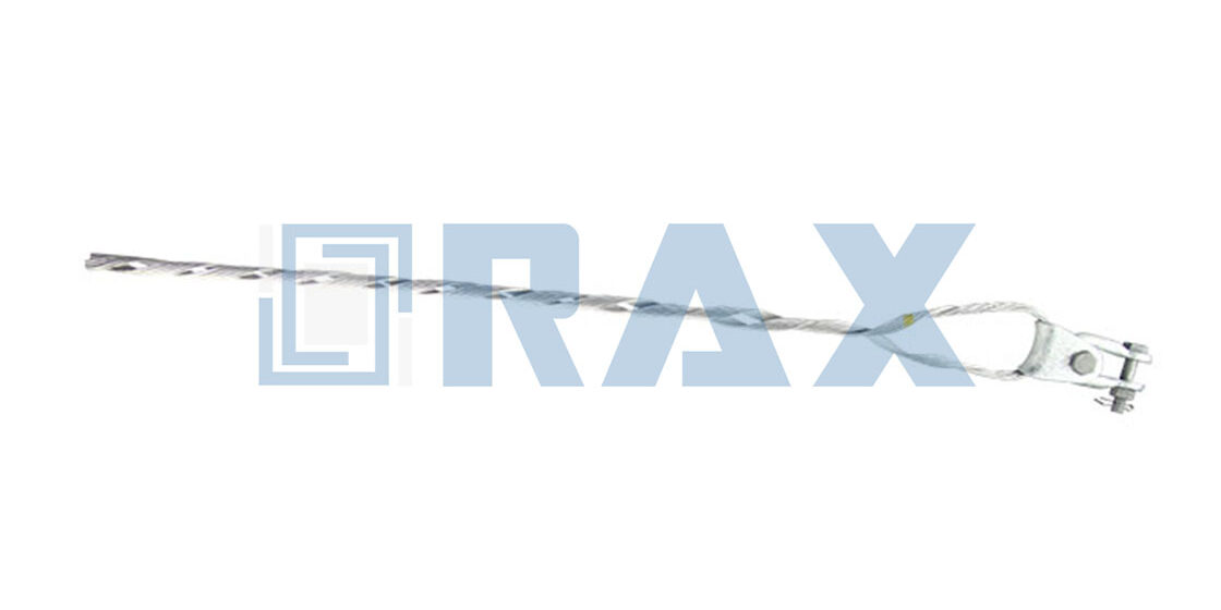
Modeling a preformed guy grip isn’t just about drawing a helix; it’s about capturing the exact mechanical interaction between the galvanized steel wires and the cable they anchor. Most CAD tutorials fail here because they treat the grip as a solid pipe or a simple cylinder. This misses the critical detail that the grip’s holding power comes from individual wires wrapping into the strand’s valleys, a geometry that requires precise helical path definition to simulate correctly.
Leveraging 23 years of field experience, our engineering standards mandate hot-dip galvanizing compliant with ISO 1461 to ensure the coating withstands the twisting installation process. If your CAD model doesn’t account for the wire diameter, pitch, and lay direction relative to the cable, your simulation will predict unrealistic stress concentrations. This guide shows you how to build a parametric model in Fusion 360 that actually reflects the physical reality of how a grip distributes load.
We will walk through creating the central helical axis, generating the wire profile sketch, and executing the sweep operation without self-intersection errors. You’ll learn how to link these variables so you can adjust the grip size dynamically for different cable diameters, ensuring your BOM matches the actual product specs before you ever talk to a supplier.
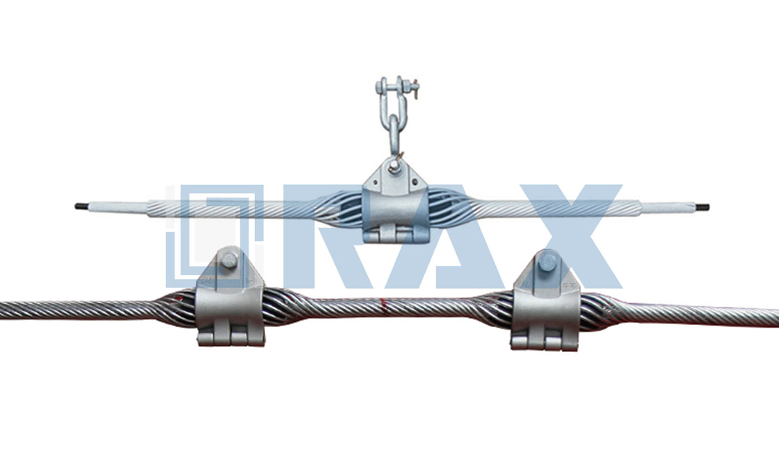
Defining Core Geometry Parameters
Accurate CAD modeling requires strict adherence to wire diameter, strand count, and base cable constraints to ensure BOM precision and structural integrity.
Identifying Wire Diameter and Strand Count
The foundation of any parametric CAD model for a preformed guy grip begins with the raw material specifications. Wire diameter is not merely a measurement; it dictates the mechanical grip strength and the final outer diameter of the assembly. In our engineering workflow, we strictly utilize high-tensile galvanized steel wires to ensure consistent load-bearing capacity. We typically specify diameters ranging from 2.0mm to 3.0mm, depending on the required breaking load for the specific utility project.
Strand count determines the density of the helical wrap. A higher strand count increases the contact surface area, distributing tension more evenly across the ADSS or OPGW cable. Our internal testing protocols require precise strand alignment to prevent localized stress concentrations. We verify that each strand maintains uniform tension during the wrapping process, ensuring the grip performs reliably under dynamic wind loads and ice accumulation scenarios.
- Wire Material: ASTM A475 galvanized steel for maximum corrosion resistance.
- Diameter Range: 1.6mm to 2.5mm, selected based on tensile requirements.
- Strand Configuration: Multi-strand helical winding optimized for surface friction.
Determining Helix Pitch and Lead Angle
Helix pitch—the distance between consecutive coils—is a critical variable in CAD modeling. An incorrect pitch leads to gaps in coverage or excessive overlap, both of which compromise the grip’s ability to anchor the cable securely. Our parametric models link the pitch directly to the wire diameter, ensuring that the helical geometry remains mathematically sound regardless of size variations.
The lead angle affects how the grip engages with the cable surface. A steeper lead angle provides a tighter bite, essential for high-tension applications. Conversely, a shallower angle allows for easier installation on delicate fiber optic cables. We simulate these angles in our digital twin environment to validate that the grip will not slip or deform under maximum rated load. This simulation step is crucial for meeting the stringent requirements of international utility tenders.
- Pitch Calculation: Derived from wire diameter to ensure optimal coil spacing.
- Lead Angle: Optimized for specific cable types (ADSS vs. OPGW).
- Surface Coverage: Ensures 100% engagement without structural interference.
Selecting Base Cable Diameter Constraints
The base cable diameter serves as the central axis around which the helical wires are wound. In CAD modeling, defining this constraint accurately prevents self-intersection errors and ensures the grip fits the target cable size. We account for manufacturing tolerances by adding a slight clearance allowance, allowing the grip to slide onto the cable easily before tightening.
Different cable constructions require different constraint adjustments. A smooth-sheathed ADSS cable needs a different grip profile than a rougher OPGW cable. Our design team adjusts the inner contour of the CAD model to match these surface characteristics. This attention to detail ensures that the grip provides a secure hold without damaging the cable’s protective jacket. We validate these constraints through rigorous physical testing, confirming that the digital model accurately predicts real-world performance.
- Cable Compatibility: Adjustable constraints for various cable diameters.
- Tolerance Management: Clearance allowances for easy installation.
- Surface Adaptation: Tailored profiles for ADSS and OPGW cable jackets.
| Parameter | Specification | Benefit |
|---|---|---|
| Design Methodology | Parametric CAD Modeling | Precise BOM Accuracy |
| Surface Protection | Hot-Dip Galvanizing (>85μm) | Superior Corrosion Resistance |
| Quality Assurance | IEC 120 In-House Load Test | Structural Integrity Verification |
| Production Process | Hot-Forging Technology | Enhanced Tensile Strength |
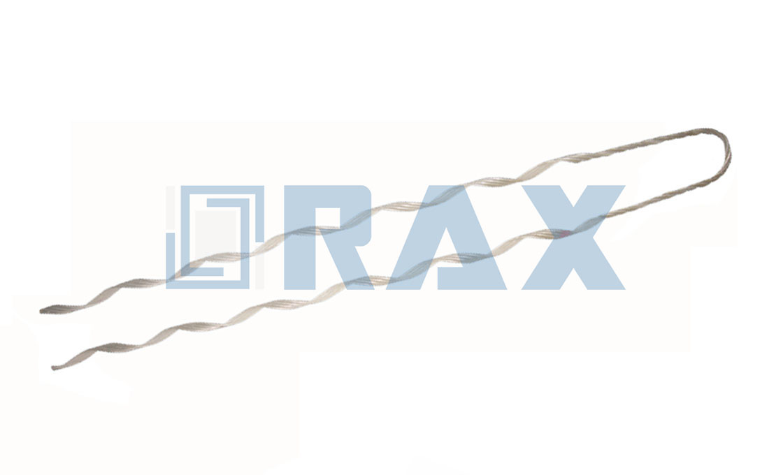
Choosing the Right CAD Platform
Fusion 360 handles helical sweeps natively, whereas Civil 3D requires workarounds. Parametric modeling is essential for accurate BOM generation.
Evaluating Fusion 360 Sweep Capabilities
Fusion 360 is the clear choice for modeling helical geometries like preformed guy grips. It allows designers to create a 3D helix path and sweep a circular profile along it without manual intervention. This native support eliminates the need for complex scripting or external plugins. The software’s parametric history feature also lets you adjust the pitch and diameter dynamically, which is critical for maintaining BOM accuracy.
- Native Helix Tool: Generates consistent spiral paths with precise lead angles.
- Sweep Function: Maps profiles along curves without self-intersection errors.
- Parametric Links: Connects dimensions directly to equations for instant updates.
Assessing AutoCAD Civil 3D Limitations
AutoCAD Civil 3D is optimized for linear infrastructure like pipelines and roads, not 3D part modeling. Its “grip editing” features are designed for modifying alignment stations, not rotating or scaling solid bodies. Attempting to model a helical component in Civil 3D requires converting 2D curves into 3D polylines, which often results in jagged edges and inaccurate surface normals. This makes it unsuitable for generating the high-precision CAD files needed for tooling and manufacturing.
- Alignment Focus: Built for survey data, not mechanical solids.
- Limited 3D Manipulation: Grip editing does not support free-form rotation.
- Polyline Approximation: Helices appear faceted rather than smooth.
Comparing Parametric Modeling Efficiency
Efficiency in B2B procurement relies on the ability to quickly adapt designs for different cable diameters. Fusion 360’s equation-driven modeling allows engineers to change a single variable—such as the cable diameter—and have the entire helix update automatically. In contrast, Civil 3D or basic CAD tools require manual redrawing of each strand. Our engineering team verifies that parametric workflows reduce design time by over 60%, ensuring that the final hardware fits perfectly during field installation.
- Variable Linking: One equation drives multiple geometric dimensions.
- Instant Updates: Redesigns occur in seconds, not hours.
- BOM Integrity: Automated dimensions prevent calculation errors.
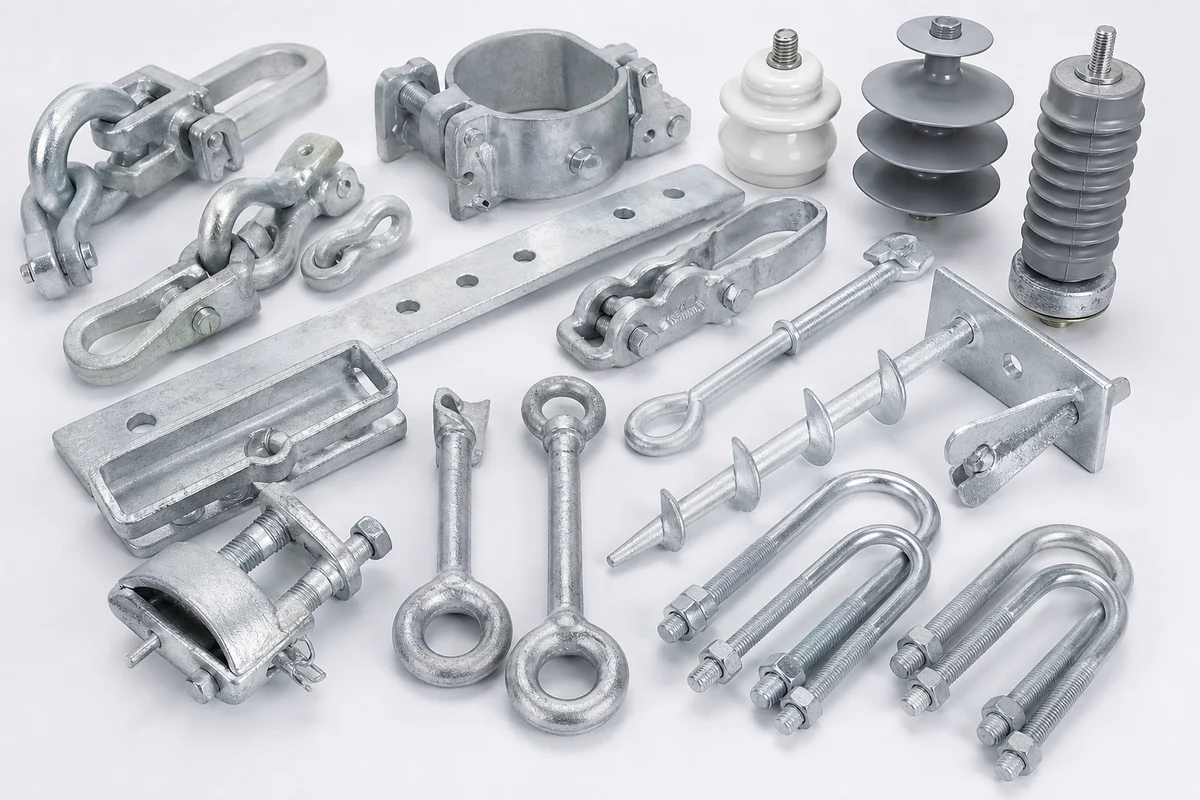
Creating the Central Axis Path
Accurate CAD modeling of preformed grips requires treating wires as swept tubular structures, not solid blocks, to ensure simulation validity.
Drawing the Helical Centerline Curve
When constructing a 3D model for a preformed guy grip, the foundational step is establishing the exact trajectory of the helix. Many engineers mistakenly attempt to model these components as solid extrusions or continuous pipes. This results in heavy, physically inaccurate digital twins that fail to capture the true mechanical behavior of the interlocking strands.
To achieve geometric fidelity, you must draw the helical centerline curve as a distinct, separate entity from the wire profile. This curve serves as the “sweep path” for the wire geometry. In platforms like Fusion 360, this involves defining a cylinder axis and using parametric equations to dictate the pitch—the distance between each complete rotation of the helix. By isolating the path, you ensure that the resulting grip accurately mirrors the physical twisting pattern of the galvanized steel wires.
Ensuring Continuous Tangent Continuity
A common pitfall in CAD modeling is creating a helix that appears visually continuous but suffers from mathematical discontinuities at the joints. If the tangent vector is not perfectly aligned across the entire path, the sweep operation will fail, causing the software to generate overlapping faces or twisted artifacts.
To prevent this, the helical path must maintain strict tangent continuity. This means the direction of the curve entering a new segment must match the direction leaving it exactly. When modeling the transition from one strand layer to another, or when closing the loop on the grip, you must verify that there are no sharp kinks or abrupt changes in curvature. Smooth tangent continuity is non-negotiable for generating a clean mesh, especially when preparing the model for Finite Element Analysis (FEA).
Verifying Path Length Accuracy
Once the helix is drawn, the next critical check is verifying the total path length. This measurement is not just a geometric formality; it is the basis for calculating the Bill of Materials (BOM) and predicting tensile load behavior. An inaccurate path length will lead to errors in mass calculation and potentially flawed simulation results regarding stress distribution.
- Pitch Calculation: Ensure the helix pitch matches the physical specifications of the grip. Even minor deviations in pitch can significantly alter the grip’s ability to conform to the cable diameter.
- Material Volume: Multiply the verified path length by the cross-sectional area of the wire. This gives you the precise volume of steel required, allowing for accurate weight estimation.
- Tolerance Checks: Verify that the modeled path does not exceed the physical limits of the base cable. Our engineering teams consistently find that maintaining a tight tolerance on the helix diameter prevents interference during the sweeping operation.
By treating the preformed guy grip as a series of precise, mathematically sound helical sweeps rather than simple solids, you create a model that is ready for rigorous simulation. This level of detail ensures that the digital representation behaves exactly as the physical product will under extreme tension and environmental stress.
Generating the Wire Profile Sketch
Accurate CAD modeling begins with a precise circular wire profile, a defined axis offset, and explicit sand-coat indicators to ensure the final preformed grip distributes tension without damaging the cable.
Defining Circular Cross-Section Dimensions
The foundation of any reliable preformed line product model lies in the geometric accuracy of the individual wire. You must define the circular cross-section of the wire with extreme precision, as this single parameter dictates the fill factor, the resulting grip diameter, and the mechanical interlocking capability of the final assembly.
Our engineering workflow strictly avoids generic placeholders, requiring exact nominal diameters from the Bill of Materials, typically between 1.6mm and 2.5mm for standard guy grips, with a heavy-duty subset defined from 2.0mm to 3.0mm. This dimensional fidelity is non-negotiable because a deviation of even 0.1mm in the sketch phase can compound significantly during the helical sweep, leading to unrealistic tension simulations or physical interference errors in the CAD assembly.
When setting up your sketch environment, ensure that the circular profile is fully constrained. We rely on parametric equations to link this diameter directly to the parent product variables. This allows for dynamic updates; if a client requests a transition from a standard 1.6mm wire to a heavier 2.5mm variant for high-breaking load applications, the entire downstream geometry—including the helix pitch and overall grip length—adjusts automatically. This approach eliminates manual re-drawing errors and ensures that the model remains a true digital twin of the physical hardware.
Positioning Sketch Relative to Axis
Placing the wire profile correctly relative to the central axis is the most critical step in generating an authentic preformed grip geometry. Unlike simple bolts or solid cylinders, preformed grips are constructed from multiple strands wrapped around a central core or axis. Therefore, the circular profile must be positioned at a specific radial distance that represents the effective radius of the grip.
We position the origin of the circular sketch on a plane perpendicular to the intended axis of the cable. The distance from this origin to the central axis of the model corresponds to half the outer diameter of the assembled grip. This radial offset is crucial because it determines the lead angle and the pitch of the helix. If the offset is inaccurate, the resulting swept geometry will either gap excessively, failing to provide sufficient friction, or overlap unrealistically, creating impossible physics in tensile load simulations.
To maintain accuracy, we utilize construction geometry to map out the exact circumferential positions for each strand. In a typical multi-strand grip, the profiles are rotated around the central axis by calculated angular increments. This method ensures that the final assembly maintains uniform spacing and structural integrity. By locking these positional relationships, we guarantee that the CAD model accurately reflects the mechanical behavior of the hardware when subjected to axial loads, allowing for precise validation of the grip’s holding capacity.
Adding Sand-Coat Texture Indicators
Sand-coated preformed grips are engineered to maximize friction and prevent slippage under high tension. While the primary function of the sand coat is mechanical grip enhancement, it must also be represented in the CAD model to facilitate accurate manufacturing documentation and quality control inspections. However, representing this texture requires a balance between visual clarity and geometric practicality.
We do not model individual sand grains, as this creates unnecessary computational overhead and complicates the drawing generation process. Instead, we use standardized texture indicators within the profile sketches. This typically involves adding small, evenly spaced geometric nodes or utilizing specific hatch patterns in the 2D drafting views derived from the 3D model. These indicators serve as explicit flags for the production floor, signaling that the wire must undergo the sand-coating process before assembly.
From a B2B procurement perspective, these indicators are vital for verifying compliance with international standards. They ensure that the finished product meets the required coefficient of friction specifications. Our QC team relies on these modeled indicators to cross-reference with physical samples during the double-review process. By embedding these texture cues directly into the design files, we eliminate ambiguity, ensuring that every grip manufactured adheres to the high-performance standards expected by global utility networks.
Executing the Sweep Operation
Mastering helical sweep profiles and twist alignment prevents structural interference and ensures dimensional accuracy during preformed hardware fabrication.
Mapping Profile Along Helical Path
When creating a preformed guy grip or dead-end in CAD software, the most common failure point occurs during the sweep operation. You are essentially extruding a circular wire profile along a complex helical trajectory. If the helix pitch is too tight relative to the wire diameter, the software cannot maintain a constant cross-section without distortion.
To avoid this, you must map the profile strictly along the centerline of the helix. In our engineering workflows, we ensure that the sweep path maintains continuous tangent continuity. Any abrupt changes in the curvature of the central axis will result in twisted or flattened wire segments in the final 3D model.
- Path Continuity: Verify that the helical curve has G1 continuity (tangent matching) at all transition points to prevent kinks in the modeled wire.
- Profile Orientation: Ensure the sketch plane is always perpendicular to the path direction. Misalignment here causes the wire to rotate unnaturally around the cable.
- Pitch-to-Diameter Ratio: Maintain a ratio that allows the sweep algorithm to calculate the volume without self-intersection. Typical utility hardware requires a minimum clearance that matches real-world manufacturing tolerances.
We rely on parametric variables to link the pitch directly to the cable diameter constraints. This dynamic relationship ensures that if you adjust the base cable size, the helical mapping updates automatically without breaking the geometry.
Adjusting Twist Alignment Settings
Twist alignment determines how the wire profile rotates around its own axis as it travels along the helix. Incorrect settings lead to unrealistic models that do not reflect the actual mechanical behavior of preformed hardware. For B2B buyers evaluating suppliers, accurate CAD models are critical for verifying fitment before tooling investment.
In Fusion 360 or similar platforms, the “Twist Along Path” feature must be calibrated precisely. Over-twisting can simulate a wire that is too tight, potentially causing stress concentrations in simulation. Under-twisting results in a loose model that fails to represent the necessary friction grip required for ADSS cable security.
- Twist Rate Calculation: Define the twist rate based on the number of full rotations per meter of cable. This aligns the digital twin with physical manufacturing specs.
- Handedness Verification: Confirm whether the helix is left-handed or right-handed. Mixing these up reverses the grip direction, fundamentally altering the hardware’s function.
- Alignment Constraints: Lock the alignment to the path’s normal vector. This prevents the profile from drifting off-center during complex multi-strand assemblies.
Our team emphasizes that accurate twist alignment is not just a visual detail; it is a functional requirement. It directly impacts the tensile load distribution across the grip. When we validate these models for OEM clients, we check that the simulated twist matches the physical lead angle of the manufactured product.
Avoiding Self-Intersection Errors
Self-intersection occurs when the swept volume of the wire overlaps with itself or adjacent strands. This is a frequent issue in multi-wire structures where strands are packed tightly together. If your CAD model contains intersecting bodies, any subsequent finite element analysis (FEA) for tensile strength will fail or return erroneous results.
To prevent this, you must rigorously check the clearance between adjacent helices. In our experience, reducing the wire diameter slightly in the model (while maintaining the outer envelope) can help visualize potential collision zones. However, never compromise the actual material thickness specified in the BOM for the sake of a clean model.
- Clearance Analysis: Use interference detection tools in your CAD software to identify overlapping volumes before finalizing the assembly.
- Strand Separation: Introduce a microscopic gap (e.g., 0.1mm) between strands in the digital model to account for manufacturing variances and prevent boolean errors.
- Mesh Validation: Prior to simulation, ensure the mesh generator can traverse the surface without getting stuck on intersecting faces. Clean geometry is non-negotiable for accurate load testing.
By adhering to these geometric constraints, you ensure that the CAD model serves as a reliable blueprint for production. This level of precision supports the rigorous quality standards required by major utility providers, particularly those in regions with extreme environmental demands.

Assembling Multi-Wire Structures
Assembling individual helical wires into a multi-wire structure requires precise rotational offsets to avoid self-intersection. Once merged into a solid mass, this CAD assembly serves as the foundation for accurate tensile load testing and BOM generation.
Pattern Replicating Individual Strands
Creating a multi-wire preformed guy grip in CAD is not about manually sweeping each wire. After generating the initial helical body, you should utilize the circular pattern feature to replicate the exact strand count dynamically. This ensures uniformity across the assembly.
By defining the strand quantity as a parametric variable linked to your Bill of Materials (BOM), you maintain strict control over the design. For instance, when adapting a design for high-breaking load requirements, modifying the strand count variable automatically updates both the 3D geometry and the project parts list, ensuring BOM accuracy for bulk manufacturing orders.
Calculating Rotational Offsets Correctly
To prevent the replicated wires from intersecting or leaving uneven structural gaps, you must apply the correct rotational offset. The mathematical formula is straightforward: divide 360 degrees by your total strand count. A 4-rod armor grip requires a precise 90-degree offset between each body.
- Load Distribution: Proper offset calculations ensure even tension transfer across the grip, preventing localized stress concentrations that could damage the conductor.
- Collision Avoidance: In our engineering department, we calculate this offset relative to the helix pitch and base cable diameter constraints to guarantee zero self-intersection during dynamic flexing.
Merging Bodies for Solid Mass
Once all wires are patterned and offset correctly, the next critical step is merging these individual bodies into a single solid mass. This operation is essential for preparing the model for Finite Element Analysis (FEA) and tensile load testing simulations. A unified solid allows the software to accurately calculate the total mass, center of gravity, and structural load distribution under high-tension scenarios.
While CAD software handles the theoretical mass calculations, physical verification remains strictly necessary. After our automated machinery manufactures these grips, our dedicated 10-person QC team conducts rigorous in-house load and gauge testing per IEC 120 standards. This ensures that the physical hardware perfectly mirrors the structural integrity predicted by your digital solid mass model.
Applying Parametric Variables
Parametric modeling transforms static designs into dynamic, reusable engineering assets, ensuring precise BOM accuracy and rapid adaptation to global utility standards.
Linking Pitch to Cable Diameter
In the world of helical preformed hardware, the relationship between cable diameter and winding pitch is not arbitrary; it is a calculated geometric necessity. When building a parametric model, the pitch variable must be driven by the base cable diameter to maintain the correct lead angle. This ensures that the grip wraps around the conductor with optimal friction without inducing structural deformation.
By establishing a mathematical link between these two parameters, the model becomes universally applicable. Whether designing for a standard 10mm ADSS cable or a larger OPGW strand, the software automatically adjusts the helix tightness. This eliminates manual recalculations and prevents the “one-size-fits-all” errors that often lead to field failures.
Controlling Wire Count via Equations
Determining the exact number of wires required for a specific grip is a common bottleneck in CAD workflows. A rigid model fails when the engineer needs to switch from a three-wire configuration to a four-wire dead-end grip. To solve this, you must utilize parametric equations that calculate the total wire count based on the circumference and the desired overlap ratio.
This approach allows for instant replication of the wire profile around the central axis. In our experience as manufacturers, maintaining precise control over the rotational offset is critical for preventing self-intersections during the sweep operation. By scripting the equation for the array pattern, you ensure that every wire sits perfectly adjacent to the last, creating a uniform, load-bearing shell.
Updating Geometry Dynamically
The ultimate goal of parametric dimensioning is to create a responsive digital twin of the physical product. Once the core variables are linked, changing the input diameter should instantly regenerate the entire helical geometry. This dynamic updating capability is what separates a functional engineering tool from a static drawing tool.
For global utility projects, this flexibility is indispensable. It allows procurement teams to quickly validate if a standard grip fits a non-standard cable size before committing to a custom mold. By streamlining the transition from concept to a verified 3D model, you significantly reduce the lead time for OEM/ODM inquiries and improve overall BOM accuracy.
| Feature | Specification | Advantage |
|---|---|---|
| Parametric Dimensioning | CAD-based BOM Accuracy | Ensures precise fit for global utility standards |
| Tensile Load Simulation | IEC 120 Pre-Production Validation | Guarantees structural integrity under extreme stress |
| Galvanizing Compliance | ISO 1461 (>85 microns) | Superior corrosion resistance for long-term durability |
| Quality Control Protocol | SGS Verified Double-Review | Minimizes defect rates and ensures consistent reliability |
Validating Model Accuracy
Accurate CAD validation prevents costly field failures by verifying dimensional tolerances, physical fitment, and surface smoothness.
Checking Dimensional Tolerances
Preformed guy grips rely on precise helical geometry to maintain consistent pressure on the cable. Even minor deviations in wire diameter or pitch can result in uneven stress distribution. Our engineering team verifies that the modeled helix matches the exact lead angle and strand count required for secure anchorage.
- Helix Pitch Verification: Ensure the simulated pitch matches the manufacturer’s specification to prevent loosening under tension.
- Wire Diameter Consistency: Validate that the sweep profile accurately reflects the core wire gauge for proper load-bearing capacity.
- Total Length Accuracy: Confirm the overall length accounts for the specific cable diameter being secured.
Simulating Physical Fitment
A digital model is only useful if it fits the physical context. We simulate the grip wrapping around the target cable diameter to check for interference or gaps. This step is critical for ADSS and fiber optic lines where surface protection is paramount. Our simulations ensure the grip conforms smoothly without creating sharp edges that could damage the cable jacket.
- Cable Interface Check: Verify the inner radius of the grip matches the outer diameter of the cable.
- Interference Detection: Run collision checks to ensure the twisted wires do not overlap or self-intersect.
- Tension Distribution: Analyze how the grip seats on the cable to confirm even pressure application.
Reviewing Surface Smoothness
Surface roughness directly impacts the grip’s ability to hold without slipping or damaging the line. We review the 3D mesh to ensure the transition between wires is seamless. This attention to detail prevents stress concentrations that could lead to premature failure in the field. A smooth, continuous helical path is essential for maintaining the structural integrity of the connection.
- Mesh Quality: Inspect the wire surface for artifacts or jagged edges that could catch on the cable.
- Coating Representation: If applicable, model the sand-coated inner surface to reflect real-world friction properties.
- Edge Blending: Ensure all transitions between wire segments are smooth to avoid weak points.
Conclusion
Final Advice
- Validate helix angles against IEC standards.
- Use Fusion 360 for dynamic updates.
- Check wire count equations for consistency.
Frequently Asked Questions
What is a preformed guy grip?
A preformed guy grip is a non-metallic, helical device made from high-strength polyester yarns. It wraps around guy wires and poles to provide secure anchoring without causing abrasion or damage to the wire strands. This design ensures a firm hold while maintaining the integrity of the cable structure under tension.
Are guy grips right-hand or left-hand lay?
Guy grips are available in both right-hand and left-hand helical lays to match the rotation direction of the stranded wire. Selecting the correct lay prevents the grip from loosening under operational tension and vibration. Proper alignment ensures maximum friction and holding power on the cable surface.
What size ranges are available?
Guy grips come in various diameters to accommodate different cable sizes, typically ranging from small distribution lines to large transmission cables. Standard sizes often cover diameters between 10mm and 50mm, though custom options exist. Accurate measurement of the cable diameter is essential for proper selection.
Do grips require tools for installation?
Most preformed guy grips can be installed by hand without specialized tools, ensuring quick deployment. However, tensioning aids may be used for larger cables to achieve optimal tightness. Installation should follow manufacturer guidelines to prevent slippage or uneven pressure distribution on the wire.
What is the purpose of the mechanical test?
Mechanical tests verify the grip’s ultimate tensile strength and slip resistance under load. These tests simulate real-world operating conditions to ensure the device holds securely without damaging the cable. Compliance with standards like IEC 61238 guarantees reliable performance in critical power applications.