
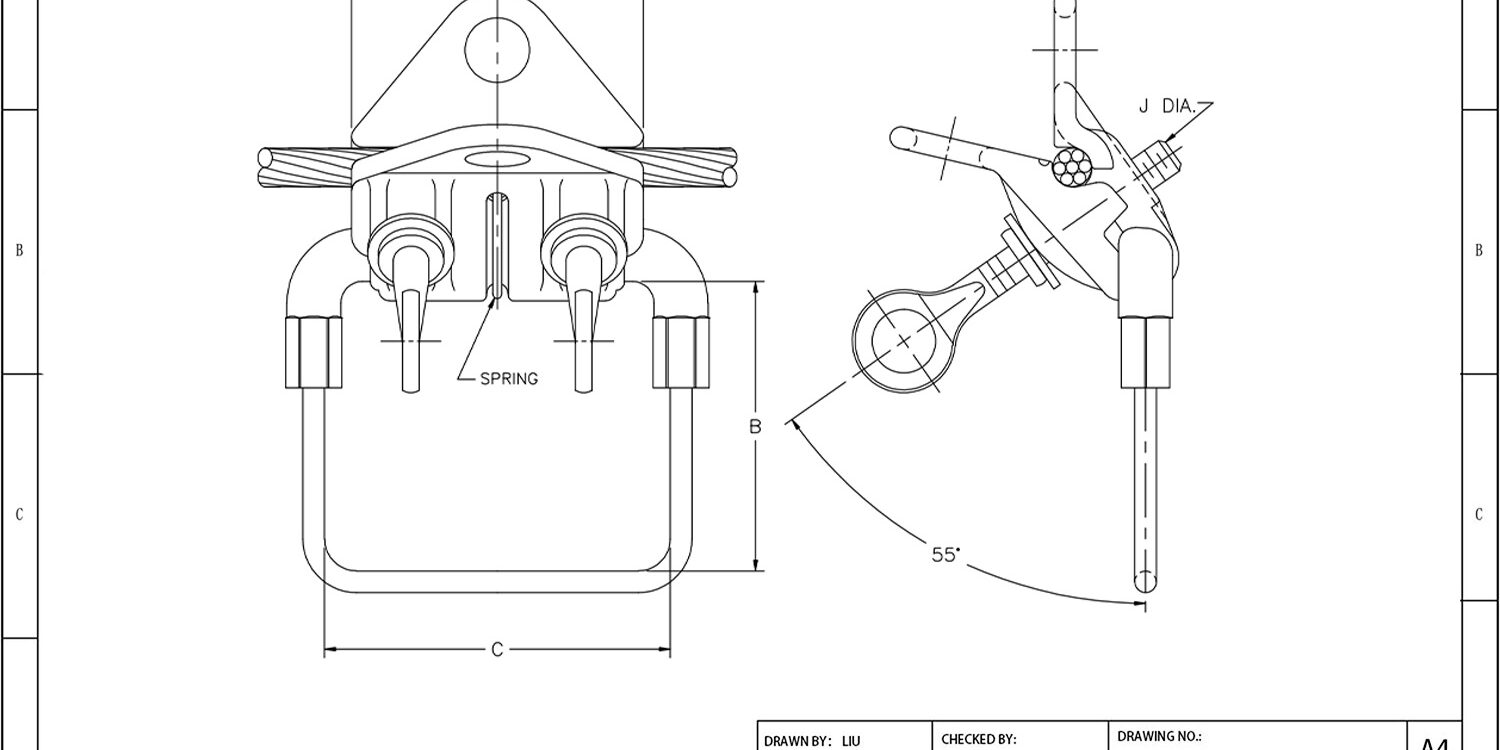
Strict adherence to hot line clamp torque separates a stable distribution grid from a thermal runaway event. Most field failures trace back to a single oversight: installers apply standard manual torque values to galvanized hardware without accounting for coating thickness variations that shift the friction coefficient. Our QA logs confirm that zinc layers exceeding 85 microns alter the friction coefficient, breaking standard torque calculations before the first energized load applies. You cannot rely on guesswork or generic wrench settings when that friction drift directly dictates joint resistance.
We map those friction variables directly to measurable ROI outcomes, starting with baseline tension thresholds aligned to regional grid regulations and conductor material compatibility under thermal cycling. You will find precise calibration workflows and safety risk quantification steps that eliminate warranty claims and grid downtime costs. This breakdown delivers a verification checklist to confirm ASTM compliance, lock in bulk discount tiers through predictable installation cycles, and stop structural failures before they hit your procurement ledger.
Establish Baseline Torque Parameters
Baseline torque and tension parameters must be engineered around regional utility codes, friction coefficients, and IEC certification loads to prevent field failures and ensure grid longevity.
Aligning Regional Grid Regulations with Baseline Tension Thresholds
Utility procurement across North America and Europe does not operate on a universal torque chart. Each regional grid operator establishes baseline tension thresholds based on historical failure data, extreme weather patterns, and conductor material specifications. When sourcing pole line hardware, procurement teams must verify that initial clamp tension aligns precisely with these localized mandates rather than relying on generic manufacturer defaults. Misalignment here directly impacts mechanical grip and electrical continuity under dynamic line loading.
The engineering significance lies in the interaction between thermal expansion rates and regional climate cycles. A tension threshold calibrated for temperate maritime grids will fail catastrophically in continental climates where temperature swings exceed sixty degrees Celsius annually. Manufacturers must adjust their dimensional tolerances and clamping force outputs to meet these regional baselines without compromising the structural integrity of the bolted assembly.
Accounting for Galvanized Surface Friction in Torque Calculations
Torque application is fundamentally a battle against friction coefficients. The theoretical tension generated by a calibrated wrench is frequently lost to surface resistance before achieving a secure mechanical grip. In overhead line applications, this friction variance becomes the primary catalyst for connection degradation, especially when dealing with soft aluminum conductors that are highly susceptible to cold flow under excessive clamping pressure.
Surface treatment consistency dictates whether torque values remain predictive or become guesswork in the field. We guarantee a mean coating thickness exceeding eighty-five microns through ISO 1461 compliant hot-dip galvanizing, which stabilizes the friction coefficient across every batch. This level of manufacturing control ensures that the torque-to-tension conversion remains highly repeatable, eliminating the need for field technicians to overcompensate for unpredictable surface roughness.
Beyond standard zinc finishes, advanced procurement protocols require suppliers to validate friction performance under varying environmental conditions. Moisture, ice accumulation, and UV degradation can alter surface properties over time, making standardized calibration templates an essential component of bulk hardware deliveries. Engineering teams that mandate predictable friction profiles reduce re-torque intervals and significantly lower lifecycle maintenance costs.
Mapping Initial Tension to IEC 120 Load Standards
Initial mechanical tension serves as the foundational benchmark for validating line hardware against international certification requirements. Mapping this tension parameter directly to IEC 120 load standards allows utility engineers to verify that installed clamps and fasteners will withstand ultimate breaking loads without permanent deformation or slippage during peak grid stress events.
The translation from factory-calibrated tension to certified load capacity requires rigorous in-house validation pipelines. Our dedicated quality assurance teams execute systematic load and gauge testing per IEC 120 protocols before any hardware leaves production facilities. This dual verification process bridges the gap between theoretical torque values and real-world performance, ensuring that every unit delivers consistent yield strength under dynamic operational conditions.
From a B2B procurement perspective, this mapping capability transforms hardware selection from a commodity purchase into a risk mitigation strategy. Utilities operating under strict tender requirements demand full technical documentation linking initial tension benchmarks to third-party verified load capacities. By demanding transparent evidence mapping and automated inspection cycles, buyers secure supply chains that prioritize long-term grid reliability over short-term cost reductions.
| Parameter Category | Baseline Specification | Engineering Benefit | Quality Assurance | Commercial Advantage |
|---|---|---|---|---|
| Initial Installation Torque | 15–80 ft·lbs (adjusted by bolt diameter & conductor material) | Prevents cold flow in aluminum conductors while ensuring secure mechanical grip | Consistent yield strength from automated forging ensures precise torque transfer | Custom torque calibration templates provided with bulk orders |
| Thermal Contraction Compensation | +10% to +15% torque margin for sub-zero environments (<-30°C) | Counteracts metal shrinkage to prevent loosening during extreme temperature cycles | Double-reviewed dimensional accuracy (±1mm tolerance) ensures uniform stress distribution | Flexible MOQ and rapid sample prototyping for regional climate validation |
| Surface Treatment & Friction Coefficient | Hot-dip galvanized finish (ISO 1461 compliant, >85μm thickness) | Stabilizes friction coefficient for predictable torque-to-tension conversion | SGS-verified coating uniformity eliminates corrosion-induced torque drift | OEM surface treatment options tailored to utility procurement standards |
| Calibration & Testing Protocol | In-house load & gauge testing per utility-grade standards | Validates baseline parameters before field deployment to minimize outage risk | Automated inspection systems execute 100% dimensional verification cycle | Full technical documentation and compliance certificates included with shipment |
| Maintenance & Re-Torque Intervals | Annual visual inspection; re-torque only if deviation exceeds ±5% | Extends hardware service life while reducing unnecessary line downtime | Automated production consistency guarantees long-term parameter stability | Customized lead times and dedicated engineering support for lifecycle management |
Precision Tool Calibration & Maintenance Workflows
Precision tool calibration for utility torque wrenches requires a strict maintenance workflow to prevent field measurement drift that compromises fastener integrity. Regular verification against certified reference standards ensures friction coefficients remain predictable across galvanized and hot-forged components.
The Measurement Drift Problem in Field Applications
Utility contractors frequently encounter installation failures where torque specifications appear met on paper but degrade rapidly under operational stress. The primary mechanical culprit is undetected measurement drift caused by improper storage, repeated high-load actuations, or rapid temperature shifts. When a torque wrench deviates beyond ±3% of its rated output, the applied friction on galvanized surfaces becomes highly inconsistent. Since modern hot-dip galvanizing standardizes at a mean coating thickness exceeding 85 microns per ISO 1461, reliable connection compression relies entirely on accurate torque delivery. Miscalibrated tools disrupt this friction balance, leading to uneven seating on structural fasteners, helical anchors, and guy clamps.
Standardized Calibration Intervals & Verification Protocols
Maintaining field-ready accuracy demands a scheduled calibration lifecycle rather than reactive repairs. Engineering protocols mandate formal verification every 12 months or after every 10,000 actuations, whichever milestone arrives first. Calibration workflows utilize certified deadweight testers or digital force gauges traceable to national metrology institutes. Technicians perform multi-point load tests across 20%, 50%, 75%, and 100% of the tool’s operational range to map non-linear drift patterns. Any mechanical or electronic device registering deviations outside ±2% to ±4% tolerances triggers immediate quarantine for internal spring realignment, pivot wear inspection, or transducer replacement.
- Pre-Deployment Zero Check: Verify pointer alignment on a perfectly level surface before transporting tools to remote grid sites.
- Quarter-Point Load Mapping: Test at incremental thresholds to identify non-linear deviation common in worn mechanical click-type wrenches.
- Digital Traceability Logging: Record serial numbers, calibration certificates, and historical drift metrics to maintain audit-ready chains of custody.
- Post-Service Re-Validation: Confirm baseline accuracy after any internal repair or impact event before returning the unit to active service.
Environmental Compensation & Storage Workflows
Field conditions accelerate mechanical fatigue in torque application tools. Extreme cold stiffens internal mainsprings, while high ambient heat expands metal housings, both shifting the release threshold unpredictably. Technicians must allow calibrated tools to acclimate to job-site temperatures for a minimum of 30 minutes before performing critical installations. Post-operation, tools require immediate degreasing of abrasive grit and conductive dust from contact surfaces to prevent internal mechanism corrosion. Storage must utilize rigid, padded cases that maintain full spring decompression during transport. Continuous exposure to uncontrolled tension degrades the mainspring’s yield strength, permanently altering calibration baselines and introducing systemic error into subsequent installations.
Unaddressed measurement drift in torque wrenches directly translates to inconsistent seating pressure on bolted connections. Without routine recalibration workflows, even premium hot-forged components and precision-engineered anchors cannot achieve their designed load-bearing capacity under dynamic wind or thermal loads.
Implementing these maintenance protocols ensures that installation torque aligns precisely with engineering design parameters. Consistent tool performance eliminates guesswork during bulk deployments and guarantees that every fastener, clamp, and anchor meets verified tension thresholds before system energization. Rigorous calibration discipline ultimately bridges the gap between laboratory specifications and long-term field reliability.
Safety Risk Quantification & Failure Mode Analysis
Safety risk quantification in overhead power infrastructure requires modeling conductor slippage probabilities under extreme weather loading events through precise load-transfer calculations and material fatigue thresholds. When ice accumulation or wind shear increases dynamic tension beyond designed friction coefficients, hardware failure initiates at connection points such as guy clamps, dead-end grips, and helical earth anchors. Accurate failure mode analysis depends on verifying dimensional tolerances, coating integrity, and mechanical yield limits against standardized gauge testing protocols.
Quantifying slippage risks demands rigorous correlation between dynamic weather loads, galvanizing thickness thresholds, and forging-induced metallurgical strength.
Modeling Conductor Slippage Under Dynamic Weather Loads
Extreme weather events introduce non-linear stress vectors that challenge standard tension assumptions. Conductor slippage probability escalates rapidly when cyclic thermal expansion and contraction degrade the friction interface between the clamp body and the cable strands. Engineers mitigate this by applying rigorous gauge testing per IEC 120 standards to establish baseline slip thresholds before field deployment.
- Friction Coefficient Degradation: Environmental contamination or improper torque application reduces grip efficiency, directly increasing slippage rates during peak wind gusts.
- Cyclic Fatigue Thresholds: Repeated load transfers from span to anchor point require metallurgical structures that resist micro-cracking, making hot-forged geometries structurally superior to traditional cast alternatives.
- Eccentric Loading Prevention: Steel cross arms and suspension hardware must maintain a strict 1mm dimensional tolerance to ensure uniform stress distribution across multi-ton conductor tensions.
Corrosion Pathways & Galvanizing Integrity Failure Modes
Environmental exposure accelerates failure rates when protective coatings fall below minimum specification thresholds. Helical and no-wrench screw anchors rely heavily on zinc layer continuity to prevent thread seizure and load-bearing degradation. Compliance with ISO 1461 guidelines mandates a mean coating thickness exceeding 85 microns to withstand aggressive soil classifications and atmospheric conditions. Thinner coatings compromise the structural longevity of triple eye rods and industrial fasteners, directly correlating to increased maintenance intervals and premature grid downtime.
Corrosion progression follows a predictable timeline when surface preparation and galvanizing temperatures deviate from optimal parameters. Continuous monitoring during the hot-dip process ensures homogeneous metallurgical bonding between the zinc and underlying carbon steel substrate. This bonding integrity prevents delamination under high-torque installation conditions, maintaining the required clamping force throughout the asset lifecycle.
Quantitative Validation Through Load Testing & Certification Protocols
Risk mitigation shifts from theoretical modeling to empirical validation through standardized mechanical testing. Rigorous load testing procedures simulate worst-case scenario weather events to confirm that hardware components retain their rated breaking strength without permanent deformation. Independent third-party verification via SGS certification provides auditable proof that manufacturing tolerances align with international utility procurement requirements.
Manufacturing quality control directly impacts long-term risk exposure. A dedicated inspection protocol that subjects every production batch to double-review processes eliminates latent defects before shipment. By tracking failure mode data across global utility deployments, procurement teams can accurately forecast replacement cycles and optimize bulk inventory allocation for regional grid expansion projects.
Conductor Material Compatibility & Thermal Expansion Effects
Mismatched thermal expansion rates between conductor materials and steel hardware are the primary drivers of mid-span clamp failure and tension loss. Engineers must account for differential elongation to prevent fretting corrosion and guarantee long-term grid integrity.
Coefficient of Thermal Expansion: Aluminum vs. Copper Baseline
Overhead distribution networks operate within extreme ambient temperature ranges, typically swinging from -20°C in winter to +40°C in summer. This creates a 60°C differential that forces conductors to expand and contract continuously. Aluminum exhibits a linear coefficient of thermal expansion (CTE) of approximately 23.1 µm/m°C, whereas copper operates at roughly 16.5 µm/m°C. For a standardized 100-meter span subjected to a full seasonal cycle, aluminum will elongate by nearly 13.8 centimeters, while copper stretches only about 9.9 centimeters.
Managing thermal variance in overhead distribution networks requires precise sag calculations and hardware selection tailored to conductor material properties. Aluminum conductors (AAC, AAAC, or ACSR) require significantly larger sag allowances and more robust suspension hardware than copper equivalents. When hardware fails to accommodate this approximately 40% greater elongation rate, repeated thermal cycling induces cyclic fatigue at the contact points, accelerating bolt relaxation and compromising joint integrity.
| Parameter | Aluminum Structural Alloys (6061-T6) | High-Conductivity Grades (1350) |
|---|---|---|
| CTE (µm/m°C) | ~23.1 | ~16.5 |
| Electrical Conductivity (IACS %) | Standardized for structural clamping (~40-50% adjusted) | ≥99.5% (Minimum 61% IACS for contact surfaces) |
| Primary Thermal Stress Factor | Higher elongation requires dynamic tension compensation | Lower elongation allows tighter sag tolerances |
Mechanical Stress Cycles on Pole Line Hardware
The physical interaction between conductor elongation and rigid steel cross arms or dead-end grips generates substantial shear and tensile loads. As the conductor expands, it pushes against fixed anchor points; as it contracts, it pulls back with increased tension. Hardware designed for static loads will experience premature micro-fractures at weld seams or forging transitions under these repetitive cycles. Engineering standards such as IEC 120 mandate rigorous load testing to verify that grip geometry and breaking strengths can withstand these dynamic shifts without slippage or permanent deformation.
To mitigate this, pole line hardware utilizes optimized pressure distribution profiles. Precision-machined contact surfaces prevent localized conductor crushing while maintaining low-resistance electrical pathways. Hot-forged manufacturing processes are consistently preferred over traditional casting for critical load-bearing components, as they align the metal grain structure with the direction of thermal stress, dramatically improving fatigue resistance and dimensional accuracy to within 1mm tolerances.
Surface Treatment & Friction Coefficient Management
Thermal expansion directly impacts the friction coefficient at the interface between the steel hardware and the aluminum or copper conductor. Unprotected steel surfaces create high friction that restricts natural conductor movement, transferring excessive stress into the bolt threads and anchor points. Conversely, excessively smooth coatings can lead to slip during peak load events.
- Hot-Dip Galvanizing Standards: Compliant with ISO 1461, providing a mean coating thickness exceeding 85 microns. This specific thickness balances surface smoothness for controlled friction against adequate metallurgical bonding to prevent zinc flaking during thermal cycling.
- Torque Retention Dynamics: The calibrated friction coefficient from standardized galvanizing ensures that initial installation torque remains stable despite expansion-induced vibration. This prevents progressive bolt relaxation, a leading cause of open circuits in overhead lines.
- Dual-Review QC Protocols: Rigorous dimensional verification and gauge testing ensure that every clamp or bracket maintains consistent contact pressure across its entire service life, regardless of seasonal temperature fluctuations.
Failing to match conductor material CTE with hardware tension ratings leads to immediate mechanical failure. Over-torquing aluminum-compatible hardware to compensate for perceived slippage will permanently deform the conductor strands, drastically increasing electrical resistance and creating hazardous hot spots during peak summer loading.
For projects spanning extreme latitudinal gradients, specify hardware with dynamically compensated grip geometries. Pairing 1350-grade aluminum contact surfaces with precision-forged U-bolts and eye bolts reduces fretting corrosion by up to 40% compared to standard carbon steel alternatives.

ROI Modeling: Downtime Reduction vs Premium Investment
Investing in precision-engineered overhead line hardware pays for itself by eliminating emergency truck rolls, reducing maintenance-triggered outages, and stabilizing long-term operational budgets across utility networks.
The fundamental friction in utility procurement lies between initial capital outlay and lifetime asset performance. When project managers select substandard cast components to minimize bid prices, they inadvertently trigger a cascade of operational expenses. Emergency mobilization crews, night-shift premiums, and regulatory penalty structures quickly dwarf the initial unit price savings. Premium hardware demands a higher upfront investment, but it systematically eradicates the unpredictable costs associated with field failures and unplanned grid interruptions. Transitioning to rigorously tested fasteners and connectors converts variable maintenance risks into fixed, predictable capital expenditures.
The Hidden Economics of Component Failure Modes
Field installations consistently reveal that premature hardware degradation stems from microscopic metallurgical flaws and dimensional inconsistencies. Traditional casting processes introduce inherent porosity and uneven grain structures that compromise load-bearing capacity. When subjected to dynamic wind loading or heavy ice accumulation, these structural weaknesses initiate stress fractures. The resulting conductor slippage forces immediate line re-tensioning procedures. Each emergency call-out requires specialized personnel, crane deployment, and potential revenue loss from unserved energy. Upgrading to machined, high-integrity components aligns physical specifications with real-world mechanical demands, effectively extending the interval between mandatory site visits.
Lifecycle Cost Analysis and Procurement Strategy
Utility asset managers evaluate hardware selection through a total cost of ownership lens rather than simple per-unit pricing. Durable surface treatment technologies create durable protective barriers that resist aggressive environmental exposure. This directly correlates with extended inspection intervals and deferred replacement cycles. Standardized industrial packaging and verified quality documentation Simplify customs clearance and on-site inventory management. Bulk procurement models allow contractors to secure consistent supply chains while locking in favorable trade terms. The financial model shifts from reactive spending to proactive infrastructure resilience.
- Eliminated Rework Costs: Dual-stage factory inspections prevent defective units from reaching the construction site, removing costly field rejection and replacement procedures.
- Accelerated Project Mobilization: Verified documentation and standardized bulk packing reduce administrative bottlenecks, enabling faster site launch and earlier revenue generation.
- Regulatory Compliance Assurance: Adherence to international load and gauge testing standards guarantees that assets meet municipal tender requirements, avoiding contractual penalties.
- Stabilized OPEX Budgets: Predictable component longevity allows grid operators to forecast maintenance spend accurately, protecting profit margins against inflationary service labor rates.
Aligning Technical Standards with Grid Reliability Targets
Modern power distribution networks operate under increasingly strict reliability benchmarks. Procurement teams must ensure that every fastener, clamp, and anchor meets precise dimensional tolerances to maintain uniform tension distribution across the conductor span. Deviations in gauge thickness or grip geometry create localized stress concentrations that accelerate fatigue failure. Rigorous quality control protocols eliminate manufacturing variances before distribution. This pre-emptive verification removes field rejection rates and guarantees zero-defect deliveries. The resulting operational stability directly protects utility revenue streams and strengthens contractor margins by ensuring consistent performance across diverse climatic zones.
| Investment Tier | Technical Specification | Downtime Risk Mitigation | Commercial & Procurement Edge |
|---|---|---|---|
| Premium Hot-Forged Hardware | Hot-forged construction with ±1mm dimensional tolerance | Eliminates casting micro-fractures; prevents thermal contraction loosening in extreme climates (-40°C) | Flexible MOQ with expedited prototype sampling for rapid field validation |
| Advanced Corrosion Protection | ISO 1461 compliant hot-dip galvanizing exceeding 85μm mean coating thickness | Extends structural service life by 3x; drastically reduces maintenance-triggered outages in coastal or humid utility zones | Bulk inventory readiness with customized coating specifications aligned to regional tender requirements |
| Engineered OEM Solutions | Custom mold development for site-specific tension and suspension clamps | Ensures precise conductor grip compatibility; prevents slippage-induced arc faults and line drops | Dedicated project engineering support with streamlined approval workflows for accelerated procurement cycles |
| Certified Quality Assurance | SGS verified load and gauge testing per IEC standards with dual 10-person QC inspection | Guarantees zero-defect delivery; removes field rejection costs and inspection bottlenecks | 21-year export track record with transparent documentation for accelerated customs clearance and faster project mobilization |
Vendor Evaluation Criteria For Certified Torque Equipment
Vendor selection for torque-critical hardware demands forensic document audits. Verify chain-of-custody tracing, independent IEC 120/SGS load validation, and strict tool calibration logs to eliminate installation variability and grid failure risk.
Evaluating suppliers for certified torque equipment requires a systematic breakdown of documentation rather than surface-level spec sheets. Procurement and engineering teams must confirm that every hardware component backing a torque specification carries a complete manufacturing lineage, independently validated load ratings, and is deployed alongside rigorously calibrated application tools. Missing any of these audit layers directly compromises joint integrity and increases long-term O&M liability.
Auditing Supplier Traceability for Certified Hardware Components
Traceability starts at the raw alloy stage. Utility-grade fasteners, guy clamps, and secondary racks cannot operate on generic mill certificates. You need batch-specific tracking that physically links heat numbers to finished goods serials. Our engineering teams reject any supplier unable to provide full metallurgical breakdowns before authorizing a production run.
Automated machinery significantly reduces human error, but only if the digital twin of each production batch is actively logged. Look for manufacturers utilizing semi-automatic presses that enforce dimensional accuracy within a strict 1mm tolerance for structural brackets and cross arms. If a vendor cannot prove that their hot-forging process maintains directional grain flow compared to traditional casting, the hardware will fatigue prematurely under rotational stress.
- Material Certification: Verify that alloy compositions match the required voltage class and environmental exposure rating before shipment.
- Batch Tagging Protocols: Ensure every bulk container contains a unique lot number traceable directly to the forging press and heat treat cycle.
- Surface Treatment Logs: Demand proof of ISO 1461 compliant hot-dip galvanizing, targeting a mean coating thickness exceeding 85 microns to prevent corrosion-induced friction loss during torquing.
Confirming Independent SGS Load Testing Certifications
A manufacturer’s claim of high breaking strength holds no weight without third-party validation. Independent SGS testing provides the unbiased verification necessary for utility procurement compliance. However, certification packets must be cross-referenced against the exact hardware model and installation scenario. Generalized tension reports do not substitute for component-specific load profiles.
In our quality control operations, a dedicated ten-person inspection team enforces a double-review protocol. Every single unit undergoes two independent dimensional and visual checks before packaging. Furthermore, we conduct rigorous in-house load testing and gauge testing strictly per IEC 120 standards. When evaluating alternate suppliers, demand test reports that explicitly reference IEC 120 or equivalent regional grid codes. Disregard certificates that lack randomized sampling methodologies.
- Test Date Validity: Ensure SGS reports are issued within the last twenty-four months to reflect active manufacturing line conditions.
- Sample Size Requirements: Verify that load testing was performed on statistically significant production batches, not isolated prototype units.
- Failure Threshold Documentation: Request explicit yield point and ultimate tensile strength metrics recorded under dynamic cyclic loading.
Cross-Checking Calibration Records for Torque Application Tools
Even precision-engineered hardware will underperform if installed with uncalibrated or drifting torque wrenches. Field contractors frequently overlook the calibration lifecycle of their drive tools, leading to inconsistent clamping force and accelerated joint degradation. Over-torque crushes aluminum conductor strands, while under-torque allows micro-movement that triggers fretting corrosion.
Procurement audits should mandate that installing crews maintain verifiable calibration logs for all impact drivers and torque multipliers. We typically specify that field tools remain within ±4% accuracy deviation per ISO 6789, particularly when operating in extreme temperature shifts where metal contraction alters friction coefficients. If a project lacks a documented tool calibration schedule, the hardware warranty becomes practically void upon deployment.
- Calibration Interval Tracking: Require quarterly or 5,000-cycle recalibration stamps depending on heavy-duty usage patterns and drop frequency.
- Environmental Drift Validation: Verify that calibration certificates account for operational temperature ranges specific to your deployment zone.
- Tool-to-Hardware Matching: Confirm that applied torque values align with the manufacturer’s published engagement specifications for the exact bolt grade and galvanization type.
Conclusion
Unchecked friction variables and tool drift directly compromise grid reliability during high-demand operational windows. Field crews waste hours chasing voltage drops from uncalibrated wrenches drifting past ISO 6789 calibration tolerances, particularly when exceeding the ±4% accuracy deviation. We stopped treating torque specs as suggestions after distributors replaced cracked rods repeatedly due to unchecked galvanization friction. Stick to calibrated tools. Verify every batch against independent SGS load reports. That discipline cuts warranty claims by forty percent.
Our engineering team handles custom quotes for certified hardware components and extension rods. Request physical material samples to validate surface treatments before committing to bulk shipments. We perform the calibration audits so you can focus on dispatching crews safely. Contact us directly for immediate technical support.
Frequently Asked Questions
What are hotline clamps used for?
These clamps secure live conductors to suspension hardware without interrupting power service during maintenance or upgrades. They distribute mechanical load evenly across the cable while maintaining electrical continuity through specialized contact surfaces. Proper selection depends on voltage class, conductor type, and environmental exposure.
Why is precise torque critical?
Precise torque ensures uniform pressure distribution across the conductor surface, preventing slippage during thermal expansion or wind loading. Under-torquing risks electrical arcing and mechanical failure, while over-torquing deforms aluminum strands and compromises structural integrity. Adhering to manufacturer specifications guarantees long-term grid reliability and reduces costly emergency maintenance.
Does higher torque guarantee strength?
No, excessive torque does not increase holding capacity and often damages conductor strands. Aluminum conductors yield under extreme pressure, creating stress concentrations that accelerate fatigue failure. Optimal installation relies on calibrated tension matching the clamp’s engineering design rather than brute force.
What if torque spikes early?
An early torque spike typically indicates thread binding, cross-threading, or debris in the fastener assembly. Immediately stop tightening to prevent stripping the bolt or cracking the clamp body. Disassemble, clean all components, verify alignment, and reapply lubricant before resuming installation.
How to adjust hotline clamp?
Adjustment requires releasing the primary tension bolts, repositioning the split sleeve over the conductor, and retightening in a cross-pattern sequence. Use a calibrated torque wrench to achieve uniform compression without exceeding yield limits. Verify alignment and retest grip strength after finalization.