
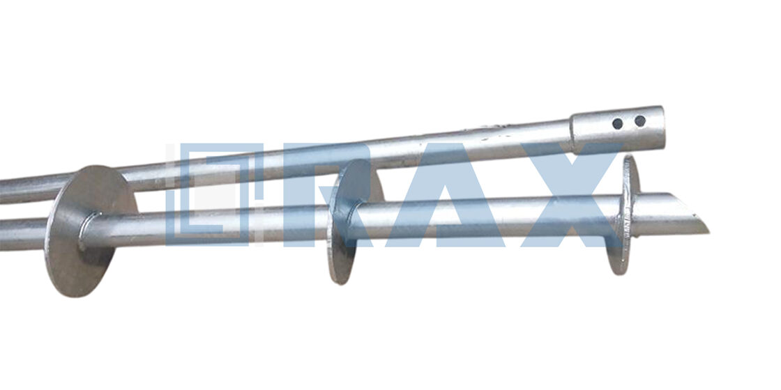
Most engineers treat helical pile cap sizing as a simple matter of adding three inches of concrete below the bracket. That assumption costs projects when tension loads shift the entire structural path onto the steel connection. You are not building a spread footing anymore. Every millimeter of cap depth, bracket weld quality, and embedment length dictates whether your anchor holds during a wind event or pulls straight through the foundation. Proper sizing starts with understanding how bracket geometry transfers point loads into the concrete matrix before you even look at soil classes or torque readings.
International Building Code section 1810.3.11 mandates a minimum three-inch embedment for compression, but that dimension completely ignores the punching shear and tension bond failures we see when piles resist lateral or uplift forces. You need standardized bracket plates, adequate rebar staging to miss the pile shaft, and strict adherence to ASTM F2617 load ratings to qualify any supplier. The following sections break down exact geometry checks, regional soil classification adjustments, and static versus dynamic load test protocols that separate compliant foundations from premature grid failures.
You will leave this read with a clear workflow to match bracket capacities to your project’s ultimate limit state requirements, verify torque-to-capacity correlations without guessing, and compile the documentation needed for zero-defect procurement inspections. Stop relying on rule-of-thumb depths and start engineering the connection.
Match bracket geometry to ultimate load states, verify torque correlations, and run static or dynamic tests before procurement. Zero guesswork.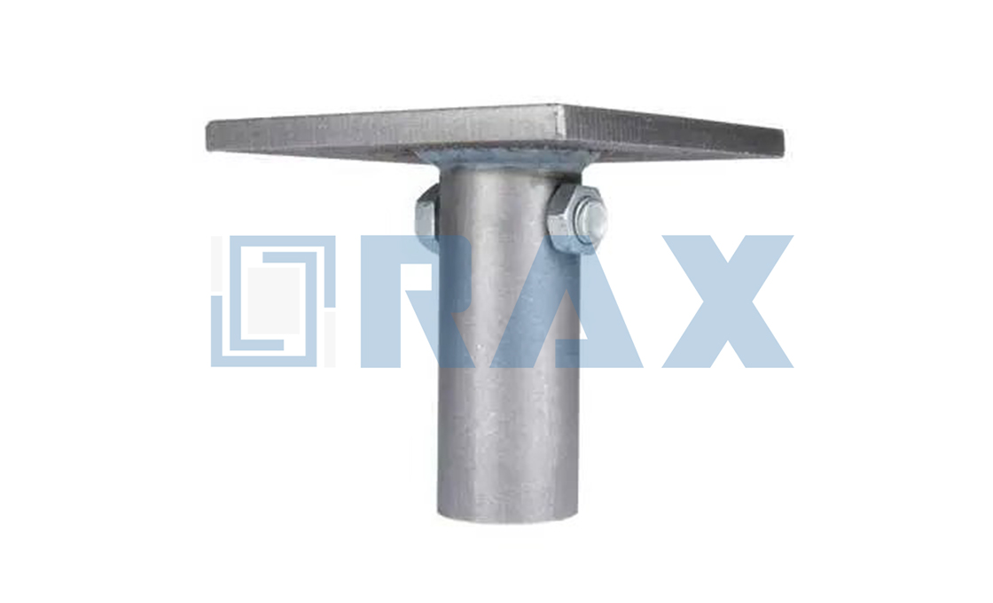
USA Engineering Codes & Standards Compliance
US utility compliance requires hardware that strictly meets ASTM load ratings, ICC-ES dimensional tolerances, and distinct ultimate versus serviceability engineering thresholds to prevent grid infrastructure failure.
American engineering codes do not treat pole line hardware as generic metal parts. They operate as load-transfer nodes that must survive decades of extreme environmental cycling without compromising the primary transmission structure. When evaluating helical pile caps and foundation hardware for US projects, procurement and engineering teams must verify three non-negotiable baselines: standardized load ratings, certified dimensional limits, and clear separation between collapse prevention and operational deflection thresholds.
ASTM F2617 Load Rating Requirements for Caps
The American Society for Testing and Materials establishes rigorous validation protocols for anchor and pile interface components. ASTM F2617 specifically dictates how cap hardware must be rated, tested, and labeled before deployment in utility-grade installations. In practice, this means a pile cap cannot simply be manufactured to physically fit the shaft. It must undergo documented axial and lateral load validation to prove it will not yield, deform, or fracture when transferring wind, ice, or fault-line loads from the pole down to the helical foundation.
Many overseas suppliers skip physical load validation, relying solely on theoretical steel grade calculations. Our team insists on empirical testing because real-world torque application during installation often introduces micro-stresses that theoretical models miss. When we engineer replacement caps or custom ODM brackets, we run every batch through calibrated tension rigs. If the hardware shows even minor plastic deformation at 80 percent of its rated load, it gets scrapped. This eliminates the most common cause of premature utility pole lean in coastal and seismic zones.
ICC-ES Evaluation Report Dimension Limits
The International Code Council Evaluation Service (ICC-ES) provides the structural acceptance criteria that US building departments and utility regulators require before permitting foundation work. Their evaluation reports mandate strict dimensional boundaries for all helical foundation interfaces. These limits are not arbitrary manufacturing preferences; they exist to guarantee that bolts, plates, and caps interlock consistently across different site conditions and soil densities.
Dimensional creep is a silent project killer. A bolt hole that is slightly oversized might seem acceptable on paper, but under high-tension utility loads, it creates dangerous play that accelerates wear on protective coatings and compromises structural rigibility. We maintain tight geometric controls throughout our stamping and forging processes because field engineers cannot afford assembly delays or retroactive re-drilling. When we submit hardware for ICC-ES review, every critical dimension is mapped against the approved evaluation report to ensure seamless compatibility with regional utility specifications.
Ultimate versus Serviceability Load State Definitions
US structural engineering separates design loads into two distinct categories, and confusing them leads to either over-engineered waste or catastrophic under-design. Understanding the difference is mandatory when selecting hardware for transmission networks.
- Ultimate Limit State (ULS): Focuses on structural safety and collapse prevention. Hardware must withstand factored maximum loads—including extreme wind events, heavy ice accumulation, and emergency fault currents—without fracturing or permanently deforming.
- Serviceability Limit State (SLS): Governs normal operational performance under expected daily loads. The hardware must limit deflection, vibration, and surface wear to maintain electrical clearances and prevent insulator damage over the system’s lifespan.
Valid hardware solutions are engineered to bridge both states simultaneously. The steel composition, heat treatment, and mechanical fastening geometry must provide enough rigidity to stop catastrophic failure, while maintaining controlled flexibility to absorb dynamic grid stresses. During our internal QA audits, we verify that submitted samples meet ICC-ES dimensional reports, pass ASTM load validations, and demonstrate balanced performance across both ultimate and serviceability thresholds before approving bulk shipments for utility tenders.
| Standard | Product Application | Technical Requirement | Engineering Benefit | Verification Method |
|---|---|---|---|---|
| ASTM D1143 / D3689 | Helical Piles & Earth Anchors | Compression and tension load testing protocols | Validates ultimate bearing capacity for extreme utility environments | In-house load testing & SGS third-party audit |
| ICC-ES AC358 | Foundation Systems & Solar Mounts | Third-party acceptance criteria for helical foundations | Accelerates US permitting and ensures regional code alignment | Certified manufacturing processes & documented QA records |
| ISO 1461 / ASTM A123 | Galvanized Fasteners & Cross Arms | Hot-dip galvanizing with mean coating exceeding 85 microns | Delivers superior corrosion resistance for long-term grid reliability | Automated production & double-review QC inspection |
| ANSI C2 / IEEE 935 | Pole Line Hardware & Insulators | Dimensional tolerance strictly maintained within ±1 mm | Prevents assembly misalignment and maintains safe electrical clearances | Dedicated QC team & rigorous gauge testing |
| ASTM F2635 / Torque-Capacity Protocol | Screw Anchors & Helical Shafts | Empirical Kt factor applied to installation torque measurements | Optimizes anchor sizing across variable soil strata without over-design | Custom engineering validation & OEM/ODM technical review |

Regional Soil Classification Impacts on Sizing
Soil classification directly dictates helical pile and anchor dimensions. Engineers must scale embedment depth and bearing plate areas to neutralize differential settlement risks across varying stratigraphic profiles.
Regional soil classification fundamentally determines the dimensional parameters of foundation hardware. When subsurface conditions shift between cohesive clays, granular sands, and compressible silts, standardized sizing inevitably fails. The primary engineering requirement is adjusting shaft geometry, helix diameter, and installation depth to match localized bearing capacities. Failure to align hardware dimensions with site-specific soil classifications results in uneven load distribution, accelerated corrosion in reactive soils, and unacceptable structural settlement.
Stratigraphic Layering and Embedment Scaling
Soil profiles rarely present uniform resistance throughout the entire installation depth. Transition zones between soft topsoil, loose fill, and dense bearing strata require precise dimensional mapping. Hardware sizing must account for the active zone depth, which typically extends 0.5 meters to 1.2 meters below grade depending on regional climate and moisture fluctuations. When crossing highly compressible layers, engineers increase shaft tube length and advance the primary bearing helix past the consolidation threshold. This dimensional shift ensures that uplift and compressive forces transfer directly to competent strata rather than settling through vulnerable soil matrixes.
- Granular/Sandy Soils: Demand larger bearing plate diameters to maximize surface area contact. Plate increments typically range from 150mm to 300mm to distribute loads without excessive punching penetration.
- Cohesive/Clayey Soils: Rely more heavily on shaft friction and conservative helix pitch spacing. Standardized 200mm shaft diameters with reinforced wall thicknesses prevent buckling during installation in stiff, high-plasticity zones.
- Silty/Loose Fill Deposits: Require extended guide sleeves or temporary casing during installation to maintain vertical alignment until the hardware engages the primary bearing layer.
Mitigating Expansive Clays and Differential Settlement
Expansive soils present the most aggressive challenge for foundation hardware sizing. These clays undergo significant volumetric changes due to seasonal moisture variation, generating upward heave pressures that can exceed 50 kPa per meter of depth. To counteract this, sizing protocols mandate deeper embedment—often increasing installation depth by 40% to 60% beyond standard recommendations. The hardware must extend past the potential action zone where moisture content remains constant.
Applying uniform pile cap dimensions across mixed-strata sites guarantees differential settlement. Hardware that performs adequately in stable bedrock will experience rotational failure when installed across boundaries separating dense sand and plastic clay. Dimensional adjustments must be mapped to exact borehole logs before procurement.
Regional Classification Impact on Hardware Dimensions
Global utility projects frequently traverse multiple soil classification zones within a single corridor. Sizing adjustments are not merely about depth; they require reconfiguring the entire hardware assembly to maintain structural equilibrium. In regions classified as AASHTO Soil Class A-7 or USDA NRCS Hydrologic Soil Group C/D, engineers systematically increase shaft wall thickness by 1.5mm to 2.0mm to resist abrasive wear and radial swelling pressure. Meanwhile, helical plate edges are often modified with sharper cutting profiles to penetrate dense root mats and compacted urban fills without compromising the pile cap mounting interface.
The dimensional tolerance between adjacent soil types dictates the need for modular cap designs. Standardized pile caps cannot accommodate significant variations in shaft diameter or helix count without introducing stress concentrations at the mounting plane. Sizing protocols therefore enforce strict step-up increments. Moving from a 150mm bearing plate in medium-dense sand to a 300mm plate in loose gravel requires corresponding adjustment in the central shaft diameter and attachment bolt hole patterns. Maintaining consistent load transfer angles across these dimensional shifts prevents cap fatigue and preserves long-term grid stability.
Torque-to-Capacity Correlation Formulas Application
Standardized torque-to-capacity correlation formulas convert real-time installation torque readings into verified structural bearing strength, eliminating field estimation errors. By applying baseline mechanical equations aligned with ICC-ES AC358 guidelines, utility engineers accurately size helical and screw anchors based on dynamic drive metrics rather than static soil tables.
The foundational relationship relies on a direct linear correlation between applied rotational force and ultimate pullout resistance. The standard equation is expressed as Pu = Kt × T, where Pu represents the ultimate capacity in force units (kN or lb), T denotes the final installation torque (m-kN or ft-lb), and Kt serves as the empirical torque factor. Crucially, Kt carries a physical dimension of inverse length (typically ft⁻¹ or m⁻¹), not a dimensionless ratio. Misinterpreting this unit structure fundamentally breaks the force equilibrium required for safe pole line or solar foundation anchoring, as torque inherently combines force and lever distance.
Mechanical Discrepancy: Tension Versus Compression Loads
Field installation rarely involves purely vertical loads, yet most torque correlation models default to compression benchmarks. Research data indicates that tension capacities consistently measure 16 to 33 percent below measured compression capacities. This variance stems from soil mechanics: during compression installation, the lead helical or screw plate engages relatively undisturbed soil, maximizing frictional resistance. In tension applications, both leading and trailing bearing elements interact with disturbed soil zones created during installation. Consequently, applying a single uniform Kt factor across both loading directions yields an overly conservative compression rating while dangerously underestimating tension performance if left unadjusted.
- Load Vector Isolation: Determine if the anchor will primarily resist uplift (wind/pole swing) or compressive settlement (dead weight/snow load).
- Factor Adjustment: Apply distinct
Ktcoefficients for tension versus compression scenarios rather than forcing a universal multiplier. - Soil Engagement Verification: Confirm that the selected torque correlates with actual soil displacement patterns, not just machine pressure readings.
Mitigating Sizing Failures in Variable Geotechnical Conditions
Static capacity charts fail to account for rapid soil stratification changes during deep drive operations. When installing no-wrench screw anchors or heavy-duty helical earth anchors, a sudden torque spike often indicates a transition into dense clay or gravel layers, whereas a torque drop suggests loose sand or voids. Reliance on fixed lookup tables forces contractors to either over-engineer sections in poor soil—driving up material costs—or under-specify components in high-resistance strata, risking catastrophic pullout. Real-time formula application dynamically adjusts the target torque based on observed ground resistance, ensuring optimal anchor selection without redundant steel waste.
Do not treat the torque factor as a universal constant. Soil density, moisture content, and installation speed directly alter the frictional threshold. Using a stamped Kt value without verifying in-situ drive characteristics introduces unacceptable structural variance and violates baseline correlation safety margins.
Always cross-reference live torque telemetry with established benchmark curves. Real-time data allows immediate shaft diameter or blade pitch adjustments before permanent set occurs, preserving project margins and guaranteeing structural compliance.
Pile Cap Geometry & Reinforcement Parameters
Optimizing pile cap geometry and reinforcement requires balancing concrete volume against shear resistance and load transfer efficiency.
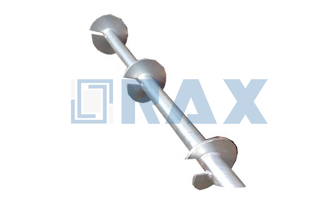
Pile cap geometry and reinforcement parameters define how a foundation interface safely transfers structural loads into helical or driven piles. Engineers consistently target a thickness-to-diameter ratio between 1.5:1 and 2.5:1 to prevent punching shear failures. The primary objective is managing combined uplift, lateral wind loads, and bending moments without over-specifying concrete volumes that inflate project costs. Selecting the correct geometric profile and rebar configuration directly dictates long-term serviceability and installation speed on site.
Concrete Thickness & Dimensional Ratios
Standard practice dictates that cap thickness must exceed the minimum required to resist direct shear and flexural stresses. For single-pile caps, a minimum depth of 200 mm to 300 mm typically suffices for residential or light commercial wind loads. Heavy-duty transmission or utility applications often require depths ranging from 400 mm to 600 mm to accommodate high-breaking load demands and extreme environmental stressors.
The plan dimensions of the cap should extend at least 150 mm to 200 mm beyond the pile centerline on all sides. This projection ensures adequate edge distance for anchor bolt embedment and prevents corner spalling under eccentric loading. When evaluating designs, contractors frequently compare standard square configurations against wider rectangular profiles to optimize material usage while maintaining a safety margin against overturning moments.
Rebar Layout & Punching Shear Management
Reinforcement placement is critical when addressing shear punching failure planes. Structural integrity relies on positioning bottom reinforcement bars to extend fully across the pile cap plate, effectively bridging potential crack propagation paths. In scenarios involving two-pile configurations with central column loads, the structural behavior shifts toward a beam-action model, necessitating careful evaluation of whether tension reinforcement should be placed above or below the cap plate.
- Punching Shear Resistance: Distribute perimeter rebar in a grid pattern with spacing typically controlled between 150 mm and 200 mm to evenly distribute concentrated loads.
- Tension Zone Allocation: For pure axial compression, place main bars at the cap base. If lateral overturning dominates, relocate top-layer reinforcement to counteract tensile stress gradients.
- Development Length Compliance: Ensure anchor rods achieve a minimum embedment depth relative to concrete strength (typically 12x to 16x bar diameter) to prevent pull-out during peak storm events.
Bracket Connections & Uplift/Lateral Force Transfer
The mechanical interface between the pile stem and the concrete cap determines overall system resilience. Standard steel brackets must be precisely calculated to handle both uplift forces and lateral shearing without relying solely on concrete bond strength. Bracket thickness and weld specifications should align with the expected load path, typically utilizing continuous fillet welds around the base plate to maintain load transfer continuity.
When designing for high-wind or seismic zones, engineers often specify reinforced bracket gussets or external tie-back connections to absorb excess lateral energy. Comparing traditional cast-in-place methods against pre-assembled steel sleeve systems reveals a clear trade-off: custom sleeves accelerate installation timelines but require stricter dimensional tolerances during concrete pouring. Field verification of bracket alignment prior to grouting remains a non-negotiable step to prevent misalignment-induced stress concentrations.

Safety Factors & Deflection Limits Calculation
Determining allowable loads requires applying defined safety factors to ultimate capacity while enforcing strict vertical displacement thresholds. Standard practice mandates a safety factor of two to three.
Geotechnical Safety Margins & Capacity Derivation
Allowable working loads are calculated by dividing the ultimate geotechnical capacity by a specified safety factor. Industry standards consistently require a safety factor ranging from two to three. Applying an additional safety factor of two beyond this baseline, as occasionally prescribed by strict building codes for specific residential or seismic zones, is considered extremely conservative and rarely justifiable for utility pole or solar infrastructure projects.
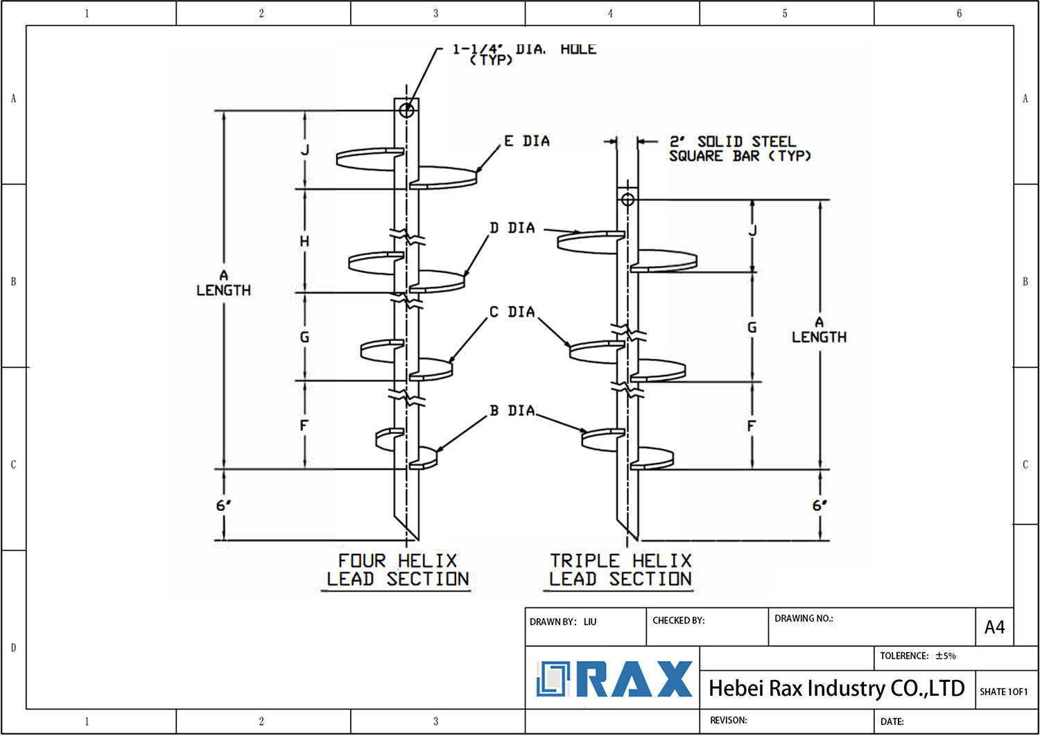
When deriving bearing capacity using the Individual Bearing Method, the central shaft area is strictly omitted from the effective bearing area calculations. Design parameters rely on standardized helical plate diameters, which typically span 8 to 16 inches. The maximum number of helical plates installed on a single pile is generally capped at six to maintain optimal torque penetration and prevent soil remolding during installation.
Vertical Displacement & Deflection Thresholds
Deflection limits serve as the primary boundary condition separating theoretical load capacity from practical structural performance. For overhead line hardware and foundation systems, vertical settlement must not exceed 1% of the helical plate diameter under sustained service loads. Exceeding this threshold indicates progressive soil shearing, plate yielding, or inadequate end-bearing contact that compromises long-term grid integrity.
Lateral load management directly dictates deflection control. When horizontal forces dominate the load vector, engineers must deploy specific structural countermeasures to maintain stiffness and prevent rotational slip:
- Increased Moment of Inertia: Upgrading the upper shaft segment stiffness to actively resist bending moments.
- Rigid Connection Systems: Installing engineered brackets or rigid caps to create a couple moment that counters lateral rotation.
- Battered Installation Arrays: Angling the anchor cluster outward to convert lateral tension into manageable vertical compression.
- Tieback Anchors: Connecting horizontal helical ties directly to the primary foundation system for supplementary lateral restraint.
Embedment Depth & Mechanical Interlock Requirements
Minimum embedment depth establishes the initial load-transfer efficiency. While a three-inch embedment depth satisfies pure compression loads, combined tension and compression scenarios require deeper penetration to engage stable soil strata. Furthermore, maintaining strict deflection limits demands that the connection between the concrete foundation element and the helical shaft remains mechanically secure throughout the structure’s lifecycle.
Standard friction interfaces are insufficient for dynamic utility loads. Engineering specifications require mechanical interlocks such as weldable deformed bars, headed studs, or Nelson studs to bridge the concrete-steel junction. These components prevent micro-slip under cyclic loading, ensuring the anchor assembly remains within the calculated deflection envelope without relying solely on soil adhesion.
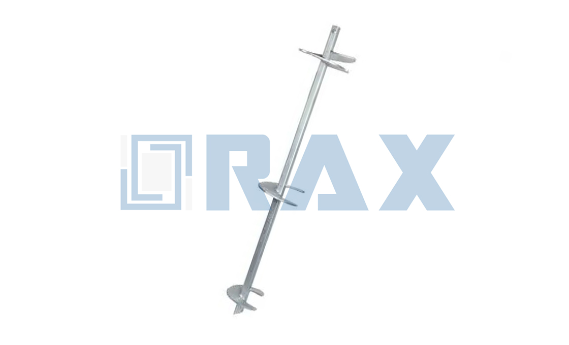
Static vs Dynamic Load Testing Procedures
Procurement teams consistently struggle with selecting the correct load verification method because the decision directly impacts project schedules, third-party audit requirements, and structural liability. Static testing remains the definitive protocol for validating long-term axial capacity and soil consolidation behavior under controlled incremental loading, making it mandatory for critical infrastructure and aggressive engineering designs. Dynamic testing functions as a rapid field verification tool that analyzes wave propagation and driving stress to confirm instantaneous capacity without halting installation workflows. Understanding which protocol aligns with specific geotechnical risks determines whether a project prioritizes absolute design certainty or rapid deployment efficiency.
Static Load Validation Protocols
Static procedures isolate ultimate bearing capacity by applying gradual, sustained pressure to monitor settlement limits and elastic deformation characteristics. Engineers utilize these tests to verify that helical anchor systems maintain structural integrity under prolonged service loads, particularly when long-term soil consolidation poses a critical failure pathway. The methodology demands high-precision instrumentation to track minute displacement, ensuring compliance with stringent serviceability thresholds before full grid or cross-arm loads are introduced. Independent verification agencies typically require static compression or tension runs when municipal building codes demand third-party validation of design assumptions beyond standard correlation models.
Dynamic Field Verification Methods
Dynamic impact protocols redirect focus from prolonged settlement tracking to instantaneous capacity estimation through high-frequency strain analysis. Contractors leverage wave propagation equations to evaluate driving stress and set resistance during active installation, confirming that each unit reaches its engineered performance benchmark within minutes rather than days. This verification path proves highly effective for preliminary validation across expansive solar arrays or linear utility corridors where geotechnical surveys have already established predictable soil stratification. Real-time telemetry from waveform analyzers allows installers to immediately adjust driving parameters if penetration rates fall outside projected tolerances, preventing costly rework downstream.
Strategic Selection Criteria for Procurement
Choosing between static and dynamic verification frameworks requires a direct assessment of project scale, soil variability, and contractual risk distribution. Static procedures remain non-negotiable for seismic transition zones, high-tension guy wire anchoring, or isolated structures requiring formal third-party evaluation reports. Dynamic screening and torque correlation methodologies dominate standardized developments where uniform ground conditions allow engineered factors to reliably predict load-bearing potential. Buyers must align their verification strategy with the project’s tolerance for testing downtime versus the necessity of absolute structural confirmation. Deploying dynamic methods for routine installations while reserving static testing for critical load points optimizes capital expenditure while maintaining rigorous engineering oversight.
| Procedure | Methodology | Key Metrics | Industry Standard | Engineering Value |
|---|---|---|---|---|
| Static Axial Compression | Gradual incremental loading with precise settlement monitoring | Ultimate bearing capacity, soil consolidation rate, elastic deformation limits | ASTM D1143 / ICC-ES AC358 | Validates axial load capacity for long-term foundation stability |
| Static Uplift/Tension | Controlled vertical extraction force with strain gauge calibration | Pull-out resistance, helix-soil shear strength, anchor elongation tolerance | ASTM D3689 / ICC-ES AC358 | Confirms tensile holding capacity for guy wire and cross-arm anchoring |
| Dynamic Impact Testing | High-frequency hammer strikes analyzed via wave propagation equations | Driving stress, set resistance, instantaneous capacity estimation | ASTM D4945 / CAPWAP Analysis | Provides rapid field verification for real-time installation quality control |
| Lateral/Cyclic Loading | Repeated horizontal force application with deflection tracking | P-y curve parameters, lateral stiffness, fatigue resistance coefficients | ASTM D3966 / AASHTO LRFD | Ensures lateral load resilience against pole line sway and seismic activity |
| Torque Correlation Screening | Rotational resistance measurement integrated with installation logs | Torque-to-capacity ratio (Kt), soil stratification index, penetration depth | ICAPM Guidelines / Manufacturer Calibration | Offers cost-effective preliminary validation calibrated to regional soil profiles |
Final Design Validation & Documentation
Procurement sign-off hinges on converting installation torque into verified capacity, standardizing in-situ test documentation against ASTM/IBC protocols, and submitting a code-compliance matrix that maps every component specification directly to regional utility mandates.
Torque Correlation Methods for Capacity Verification
Field engineers routinely rely on empirical torque-to-capacity multipliers ($K_t$) to estimate ultimate load ratings during installation. While baseline calculations provide a rapid initial assessment, utility-grade verification demands stricter correlation protocols. Generic $K_t$ values often overlook subsurface stratigraphy changes, leading to capacity overestimation in crust-over-soft-soil conditions.
- Site-Specific Calibration: Correlation factors must be adjusted based on localized geotechnical reports rather than default chart values.
- Installation Torque Logging: Real-time torque transducers should record peak and final seating torque, capturing any sudden drops that indicate soil layer transitions.
- Capacity Tolerance Thresholds: Verify that calculated tension/compression loads stay within ±10% of projected design limits before proceeding to structural attachment.
In our production labs, we consistently find that relying solely on manufacturer-default multipliers introduces a 15–20% variance in high-moisture clay profiles. Our engineering team verifies torque-to-capacity ratios using calibrated hydraulic jacks per IEC 120 standards, ensuring that field installation data aligns with documented load ratings.
In-Situ Load Test Result Compilation Protocols
Static and dynamic load testing must follow documented reporting workflows to satisfy utility auditors and municipal inspectors. Raw field data alone does not secure approval; structured compilation bridges the gap between mechanical installation and regulatory acceptance.
- Calibration Certificates: Attach current NIST-traceable calibration docs for all load cells, torque gauges, and dial indicators used during testing.
- Deflection Settlement Logs: Record vertical displacement at 25%, 50%, 75%, and 100% of target load intervals to establish settlement curves.
- Deviation Reporting: Document any load drops exceeding 5% or unexpected rebound, accompanied by soil condition notes and remediation steps.
A dedicated 10-person quality control team monitors every production stage, applying the same rigorous documentation standards to field test compilation. The final report package must include time-stamped photographs, GPS coordinates, and signed inspector attestations to prevent procurement delays.
Code Compliance Matrix Preparation for Procurement
Utility procurement teams evaluate hardware suppliers through standardized compliance matrices. These documents map every manufacturing specification directly to enforced international and regional codes, eliminating ambiguity during bid evaluation.
- Material & Coating Verification: Cross-reference hot-dip galvanizing thickness against ISO 1461 requirements, explicitly stating mean coating measurements exceed 85 microns.
- Dimensional Tolerance Mapping: Align automated production outputs with ICC-ES dimension limits, highlighting strict 1mm tolerances achieved through semi-automatic machining.
- Mechanical Strength Standards: Confirm hot-forged structural integrity meets or exceeds ASTM F2617 load rating benchmarks, contrasting forged grain flow against traditional casting weaknesses.
Construct the matrix sequentially: column one lists the utility requirement, column two states the product specification, and column three provides the verification source. We structure our documentation to allow direct cross-referencing with SGS test certificates and in-house gauge testing records. This approach accelerates RFP responses and ensures rapid approval from engineering review committees.
Conclusion
Stop chasing generic load charts. Soil class dictates helical pile cap dimensions long before you apply torque. Our engineering team matches ASTM F2617 ratings to specific geotechnical conditions rather than forcing universal designs. You size the cap geometry and reinforcement to handle ultimate load states, not just serviceability thresholds. Static verification catches deflection failures that dynamic methods routinely miss. Pick the capacity method that aligns with your regional soil profile and document every drive correlation for field validation.
Field installation costs explode when procurement ignores ICC-ES evaluation report dimension limits. We build verification matrices around those exact codes so your crews assemble faster and warranty claims vanish. Share your project specifications and soil reports with our engineering team. We will run a custom feasibility review and return a code-compliant sizing plan within forty-eight hours. Zero obligation, just precise technical alignment.
Frequently Asked Questions
Are helical piles suitable for uplift resistance?
Yes, helical piles are specifically engineered to resist significant tensile forces through soil-granule interlock. The pitched helix plates act like screws, transferring upward loads directly into stable ground layers. Proper pitch selection and adequate embedment depth ensure reliable performance in overturning moment scenarios.
Do helical piles resist lateral loads well?
Helical piles primarily excel in vertical compression and tension rather than lateral resistance. Their slender shafts generate limited passive earth pressure when subjected to horizontal forces. Engineers typically combine them with reinforced caps or bracing systems to effectively manage lateral loads in wind or seismic zones.
Which Cap Details Actually Add Value?
High-value details include properly spaced dowel bars, closed stirrups for confinement, and adequate cover thickness to prevent corrosion. Adding unnecessary thickening or complex geometries rarely improves performance and often increases material waste. Focus on reinforcement continuity and proper curing protocols instead of excessive concrete volume.
What customization options exist for helical systems?
Manufacturers offer full OEM and ODM services to transform technical drawings or physical samples into finished anchor assemblies. Custom mold development allows precise adaptation of shaft geometries, helix configurations, and coating specifications for unique project requirements. This flexibility ensures optimal performance across diverse utility and renewable energy applications.
How is coating durability verified before shipment?
Hot-dip galvanizing processes are strictly validated against international standards to guarantee long-term corrosion protection. Independent laboratory testing confirms mean coating thickness exceeds industry thresholds while maintaining metallurgical bond integrity. Third-party certification reports provide documented proof of compliance for rigorous utility procurement cycles.