
Most contractors assume arrowhead earth anchor installation is just about driving metal into dirt. They are wrong. Incorrect installation in hardpan or rocky soil destroys holding capacity before the first load test begins. We manufacture these anchors for military and commercial sites where failure is not an option, so we know that mechanical advantage only works if the anchor sets perpendicular to the pull direction.
Precision in installation mechanics determines whether a 6-inch anchor delivers its rated performance. A 6-inch anchor made from hot-dip galvanized steel delivers up to 5,000 pounds of pull-out resistance in hard pan soils when installed correctly. That number drops significantly if you skip pilot holes in compacted ground or misalign the drive rod. This guide covers the exact steps to verify site conditions, drill properly, and tension the anchor without displacing it.
You will learn how to prevent common deviation errors in loose topsoil and conduct proof load testing that actually matches project specs. Following these steps ensures your anchors hold their rated capacity through years of service.
Check Your Site and Tools Before You Start
Verify Soil Composition and Bearing Capacity
The primary variable determining the success of an arrowhead anchor is the geological profile at the installation site. Before deployment, contractors must analyze the soil stratigraphy to determine if the target strata can accommodate the necessary shear stress. While arrowhead anchors excel in cohesive soils—such as clays and silts—their performance relies heavily on the undisturbed ground engaging the anchor body.
If a project site presents rocky substrates or gravelly formations, standard driving methods may fail to achieve the required depth. In these scenarios, pre-drilling pilot holes becomes a non-negotiable requirement. We have observed projects where insufficient soil density testing led to premature surface heaving before the anchor reached its designed holding capacity.
Confirm Required Driving Equipment Specifications
Selecting the appropriate hydraulic hammer is just as critical as selecting the anchor itself. The equipment must generate sufficient downward force to overcome soil friction without damaging the anchor’s driving mechanism. For deep installations requiring high penetration, operators must ensure the hydraulic breaker matches the output requirements of the specific anchor size.
Mismatched equipment is a common bottleneck in utility construction. Using an underpowered hammer in dense clay will result in stalled progress, while an overly aggressive hammer in loose sand can displace the surrounding soil, reducing ultimate holding capacity. Verify that your drive rod connections are compatible with your selected hammer chuck to maintain continuous down-force transfer during the drive cycle.
Inspect Anchor Shaft Integrity Before Deployment
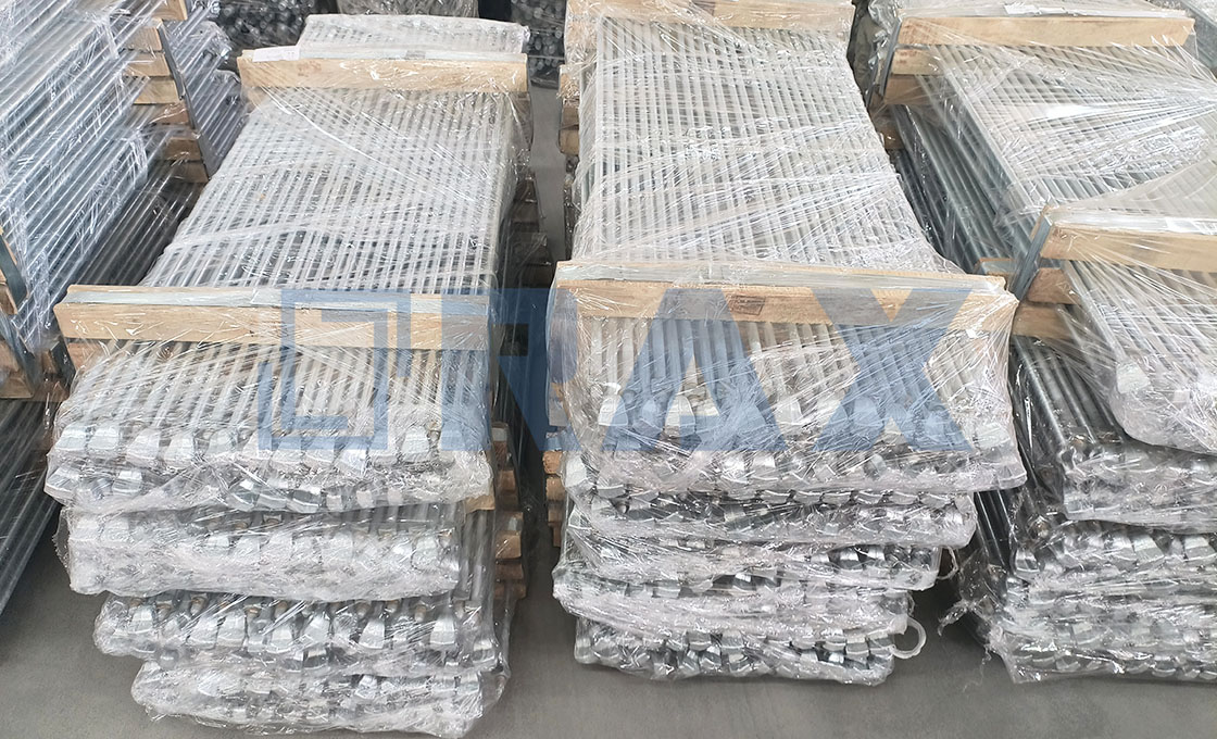
Because arrowhead anchors must be driven deeply into the earth to function, they endure immense physical stress upon impact. A microscopic bend or surface defect in the anchor shaft or the toggle mechanism can cause catastrophic failure during the tensioning phase. It is mandatory to perform a visual and physical inspection of every batch before it leaves the logistics yard.
We prioritize hot-forging in our manufacturing process because it aligns the metal grain structure for maximum toughness, superior to traditional casting methods. However, field damage can still occur. Inspect the drive head for deformation and check the pivot points of the anchor blade to ensure smooth rotation. Any anchor showing signs of corrosion pitting or mechanical bruising should be rejected immediately, as these flaws compromise the structural integrity required for critical overhead line support.
| Feature | Specification | Advantage |
|---|---|---|
| Core Design | Hot-Forged Aluminum Alloy or Galvanized Iron Construction | Superior strength and precision compared to traditional casting |
| Installation Mechanism | Toggle-Action Design Rotating 90-Degrees Perpendicular to Tension | Engages undisturbed soil for maximum holding capacity without pre-drilling |
| Surface Finish | Hot-Dip Galvanizing (ISO 1461 Compliant, >85 Microns Mean Thickness) | Ensures long-term durability in extreme environmental conditions |
| Quality Assurance | 10-Person QC Team, Double-Review Inspection, In-House Load Testing (IEC 120) | Guarantees structural integrity and dimensional accuracy |
| Certification & Compliance | SGS Verified Processes and Products | Meets rigorous global utility standards for power and solar foundations |
Stay Safe While Installing Arrowhead Anchors
Installing arrowhead anchors demands rigorous adherence to Minimum Approach Distances (MAD) and high-impact safety protocols to prevent catastrophic electrocution or mechanical injury.
Maintain Safe Distance from Overhead Power Lines
The primary lethal hazard during anchor installation is the proximity of conductive drive rods to energized conductors. Drive rods used to install arrowhead anchors are typically made of steel and act as excellent conductors. Contact—or even close proximity resulting in an arc flash—with overhead lines is immediately fatal. Operators must identify the voltage class of the nearest power lines and adhere to strict OSHA-defined Minimum Approach Distances (MAD).
- Conductive Tool Awareness: Treat the drive rod as an extension of the operator’s body. Never assume a wooden or fiberglass handle provides total insulation if the rod itself is metallic.
- Spotter Communication: When working near cross-arms or utility poles, a dedicated spotter must monitor the rod’s angle relative to overhead lines throughout the driving process.
- Voltage-Based Clearance: For distribution lines (typically 4kV to 35kV), maintain a minimum clearance of at least 10 feet (3 meters), increasing significantly for higher transmission voltages.
Secure Personal Protective Equipment for Operators
Installing arrowhead anchors is a high-impact activity involving heavy hammers or hydraulic drivers. The kinetic energy transfer creates significant risks for flying debris, pinch points, and noise-induced hearing loss. Standard construction PPE is often insufficient; task-specific gear is required to mitigate the unique risks of driving anchors into compacted soil.
- Eye and Face Protection: Safety glasses with side shields are the minimum requirement. Full face shields are mandatory when using portable hydraulic hammers to protect against high-velocity soil fragments or metal shavings released during impact.
- Impact Gloves: Operators must wear impact-resistant gloves to protect hands from the shock vibration of the driver and from pinch points during the connection of drive rods to the anchor eye.
- Hearing Protection: Hydraulic drivers and sledgehammers can exceed 100 dB. Double hearing protection (plugs plus muffs) is necessary for prolonged installation tasks to prevent permanent hearing damage.
- Steel-Toed Footwear: Essential for protection against dropped tools or the heavy drive rod itself, which can easily crush standard footwear if it slips from the driving position.
Monitor Hydraulic Pressure During Installation Process
When using portable hydraulic power units to drive anchors, monitoring system pressure is critical for both safety and installation integrity. Hydraulic systems store immense potential energy; a sudden failure in a hose, fitting, or the driver head can release high-pressure fluid that can penetrate skin, causing serious injection injuries. Furthermore, uncontrolled pressure spikes can cause the anchor to “kick back” or deviate unpredictably.
- Pressure Gauge Monitoring: The operator must continuously watch the pressure gauge. If the pressure spikes to the maximum rated PSI of the tool without the anchor advancing, driving must stop immediately to prevent equipment rupture.
- Hose Inspection: Before connecting the hydraulic unit, inspect all hoses for bulging, fraying, or leaks. Never use hands to check for leaks in a pressurized line; use a piece of cardboard.
- Dead-Head Prevention: Avoid running the hydraulic pump in a “dead-head” state (flow is blocked but pressure builds) for more than a few seconds. This generates rapid heat that can degrade seals and cause catastrophic failure.
Drill the Pilot Hole for Hard Soil
Why Pilot Holes Are Non-Negotiable in Hardpan Soil
In hardpan or densely compacted soils, skipping the pilot hole is a critical installation error that leads to structural compromise. When an anchor is driven directly into unyielding earth without pre-drilling, the extreme friction forces the soil to displace laterally rather than axially. This lateral displacement creates a loose, uncompacted “heel” zone immediately beneath the anchor head, effectively destroying the bearing capacity required for secure anchoring.
For high-load applications such as power transmission guy wires, this gap can reduce holding capacity by up to 40%, leading to premature slippage under tension. The pilot hole serves to relieve this radial pressure, allowing the anchor’s flanges or helical plates to compress the surrounding soil tightly against the shaft, ensuring maximum friction and load transfer efficiency.
Pilot Hole Sizing and Depth Specifications
The dimensions of the pilot hole are not arbitrary; they must be precisely calibrated to the anchor’s geometry to balance ease of installation with soil integrity. For standard screw anchors or plate anchors, the pilot hole diameter should typically match the outer diameter of the anchor shaft or be slightly undersized (by 1-2mm) to maintain soil friction against the sides of the anchor.
- Diameter: Match the anchor shaft OD for screw anchors; use a slightly smaller diameter for plate anchors to ensure tight soil compression.
- Depth: Drill to a depth equal to 90-95% of the anchor’s total length to leave a small buffer that ensures full seating without bottoming out prematurely.
- Tooling: Use a auger bit compatible with the expected soil density; in rocky conditions, a rotary hammer may be necessary to break up initial resistance before switching to standard drilling.
Drive the Anchor Deep and Straight
The Mechanics of Vertical Alignment
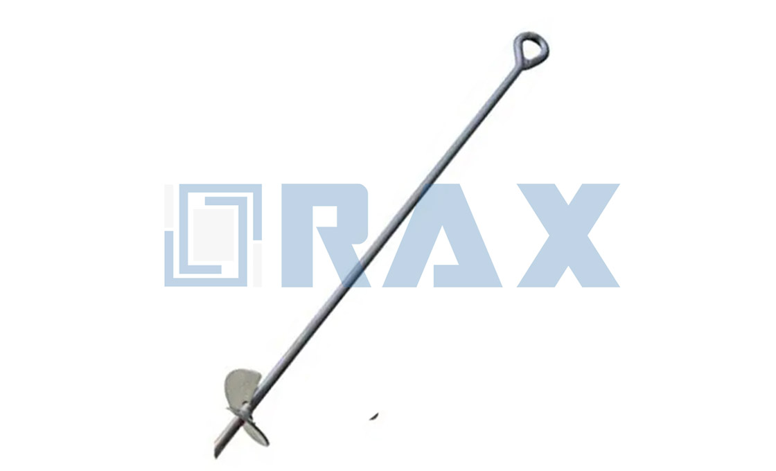
Driving an arrowhead anchor off-axis introduces immediate lateral stress that the helical shaft cannot withstand. When the anchor is not driven perfectly vertical, the flanges do not engage the soil uniformly. This misalignment causes one side of the anchor to cut through the ground while the other drags, effectively reducing the holding capacity and increasing the risk of shaft buckling during the extraction or driving phase.
To ensure a straight installation path, operators must use a guide pipe for the initial penetration into the first few feet of soil. Once the anchor head is stabilized within the guide, the driving force can be applied directly to the drive rod. This mechanical constraint prevents the helical flighting from digging into loose topsoil and forcing the anchor to veer off-center before it reaches the denser bearing strata.
Achieving Full Penetration Depth
Holding capacity is directly correlated to embedment depth. An arrowhead anchor relies on the shear strength of the soil below the active zone. If the anchor is stopped prematurely due to high torque resistance, the structural integrity of the entire support system is compromised. The drive rod must be extended and driven until the anchor head reaches the specified design depth indicated in the engineering plans.
- Soil Classification: In dense clay or gravel, reaching full depth may require higher hydraulic pressure. Do not mistake resistance for refusal; verify that the drive equipment has sufficient tonnage before altering the installation plan.
- Depth Verification: Use calibrated drive rod markings to track penetration precisely. Visual estimation from the surface is inaccurate and leads to unpredictable performance variations across different test points.
- Shaft Integrity: Ensure the connection between the drive rod and the anchor head is fully seated before applying torque. A slipped connection can strip the splines, preventing further advancement.
Remove the Drive Rod Without Displacing It
Successful rod extraction relies on releasing the mechanical lock between the drive rod and the anchor head before applying upward force. Premature upward pulling is the primary cause of anchor displacement.
The final phase of installing a no-wrench earth anchor involves separating the installation tool (drive rod) from the anchor itself. This step is technically delicate; the mechanism that holds the anchor to the rod during installation is designed to withstand significant impact forces. Consequently, a direct vertical extraction force will often pull the anchor back toward the surface or dislodge it from the locked position, compromising the holding capacity that was just established. To remove the drive rod without displacing the anchor, operators must utilize a specific disengagement sequence that breaks the mechanical connection while the anchor remains under tension.
The Disengagement Protocol
For standard arrowhead and duckbill anchor systems, the anchor must be fully set and tensioned before the drive rod is removed. This means the anchor head has rotated 90 degrees to engage the soil in its load-bearing orientation. Once the anchor is set, the rod is effectively “trapped” inside the mechanism. Attempting to yank the rod out at this stage will drag the anchor upward with it.
📋 Actionable Steps
- Step 1: Verify the “Set” Position: Confirm the anchor is fully tensioned. The anchor rod or guy wire should be under load, indicating the head has rotated perpendicular to the direction of pull.
- Step 2: Apply Downward Pressure: Before pulling up, apply a brief, sharp downward force on the drive rod. This action is critical for many toggle-style mechanisms as it disengages the retaining latch or key inside the anchor head.
- Step 3: Maintain Line Tension: While holding the drive rod, ensure the guy wire or anchor rod remains taut. Do not let the line go slack, as this allows the anchor to relax or rotate in the soil.
- Step 4: Extract the Rod: With the latch released and the line taut, smoothly withdraw the drive rod. The anchor head should remain embedded in the soil, detached from the installation tool.
In cases where the rod refuses to disengage, operators should avoid excessive hammering or violent prying. This typically indicates that the anchor has not fully rotated to the set position, or soil friction is binding the mechanism. The solution is to re-tension the guy wire to ensure the anchor is fully seated, then repeat the downward-pressure impulse to trigger the release mechanism.

Tension and Test the Anchor Properly
Tensioning and testing are the critical conversion points where theoretical load calculations become verified structural reality. Rigorous verification is the only safeguard against latent soil failure.
Applying Initial Tension to Set the Anchor
Once the drive rod is removed, the anchor must be “set” by applying an initial tension load. This process is not merely about tightening the guy wire; it is essential to rotate the anchor head or shift the expanding mechanism into its locked position perpendicular to the soil layers. Without this specific setting force, the anchor may sit in the ground in a neutral or partially engaged state, significantly reducing its holding capacity. The initial tension must be applied steadily to mobilize the soil shear strength immediately surrounding the anchor head, ensuring that the load path is established correctly before any permanent structure is attached.
Field engineers must ensure the guy wire assembly is aligned correctly to prevent side-loading the anchor eye during this phase. A misaligned pull during initial tensioning can create a bending moment on the anchor shaft, potentially compromising the structural integrity of the installation before it even bears load. The objective is to achieve a state where the anchor is firmly engaged with the soil volume and the guy system is taut, eliminating slack that could cause dynamic shock loading later.
Conducting Proof Load Testing Procedures
Proof load testing serves as the ultimate quality assurance step for critical infrastructure. This involves applying a specific test load—typically a percentage higher than the rated working load—to the installed anchor for a predetermined duration. This “overload” simulates stress conditions that exceed normal operational limits, effectively proving that the anchor system can handle unexpected surges or environmental factors. The procedure requires the use of calibrated dynamometers or hydraulic jacks to provide precise force readings rather than relying on estimation or hand tensioning.
It is vital to document the proof load results carefully. This data provides a verifiable record that the specific anchor met the required resistance criteria for that unique soil location. Variations in soil density or moisture content can occur over short distances, so a successful test on one anchor does not automatically guarantee the performance of the next. Each critical anchor should undergo this validation to ensure uniform safety margins across the project site.
Verifying Holding Capacity Against Project Specs
Verification involves comparing the field-obtained data from the tensioning and testing phases against the project’s engineering specifications. The theoretical holding capacity provided by the manufacturer assumes ideal soil conditions. However, field conditions often vary due to substrate composition, water table levels, or backfill inconsistencies. Therefore, the verification process must account for the specific “ultimate holding capacity” (UHC) achieved on-site versus the ” allowable working load” (AWL) required by the design.
- Deflection Limits: Check that the anchor did not exceed the permissible deflection angle or vertical movement during the test. Excessive movement may indicate a shallow failure plane in the soil.
- Consistency Check: Compare results between anchors. Significant discrepancies in holding capacity across a line of anchors suggest inconsistent soil stratigraphy requiring engineering review.
- Factor of Safety: Ensure the verified capacity maintains the required factor of safety over the maximum anticipated load, including wind and ice loading scenarios.
Post-Installation Settlement and Soil Re-consolidation
An often-overlooked aspect of anchor performance is the behavior of the soil immediately after driving and tensioning. The installation process inevitably disturbs the soil structure, creating a temporary zone of reduced density around the shaft and anchor head. For the anchor to achieve its maximum long-term holding capacity, this soil must re-consolidate. This process, sometimes referred to as “setup” or “healing,” allows the soil particles to settle back into tight contact with the anchor surfaces, restoring the friction and interlock critical for holding power.
Soil re-consolidation requires a mandatory settling period between installation and the application of the full service load. In certain soil types, particularly saturated clays or loose sands, this period is crucial to prevent long-term creep or gradual slippage. Final tensioning should often be revisited after this settling window to adjust for any relaxation in the guy wire or minor shifts in the anchor position. Respecting this physical waiting period transforms a simple mechanical installation into a reliable, long-term foundation solution.
Avoid These Common Installation Mistakes
Improper installation mechanics are the primary cause of anchor failure, often leading to a 30-50% reduction in holding capacity. Ensuring vertical alignment, monitoring drive resistance, and securing head connections are critical to maintaining system integrity.
Preventing Anchor Deviation in Loose Topsoil Layers
Loose topsoil or backfilled strata presents a significant risk of anchor deviation, where the shaft drifts from the intended vertical trajectory. This deviation alters the load vector, placing uneven stress on the anchor helix or head and drastically reducing the ultimate holding capacity. In our experience with global utility projects, anchors installed off-axis by more than 5 degrees in loose soil can suffer premature pull-out before reaching rated loads.
To maintain alignment, operators must utilize a drive guide or steady the installation tool manually during the initial penetration phase. The first 30-50 cm of depth is critical for establishing the correct path. If the anchor begins to wander, it must be extracted and reset rather than forced down, as compaction against the side of the shaft creates false resistance readings.
- Use a Guide Sleeve: A drive stand or guide rod helps stabilize the top of the anchor shaft during the initial entry into loose soil.
- Monitor Entry Angle: Continuously check the perpendicular alignment of the drive rod relative to the ground surface during the first meter of installation.
- Reset on Drift: If visual inspection indicates the assembly is tilting, cease driving immediately to avoid bending the shaft.
Addressing Excessive Torque Resistance During Driving
While high installation torque typically correlates with high holding capacity for screw anchors, excessive resistance can signal mechanical failure points or incorrect anchor selection for the soil density. Continuing to apply force against a stalled anchor risks shearing the shaft or damaging the helix attachment. Rax Power utilizes hot-forging techniques rather than traditional casting for our critical anchor components, significantly increasing yield strength. However, even our high-tolerance products have physical limits defined by the steel grade and soil mechanics.
Operators must distinguish between the resistance of dense soil and the mechanical obstruction of rocks or subsurface debris. If torque spikes suddenly or the drive tool bounces, the installation should be paused. Attempting to power through an obstruction often bends the shaft, rendering the anchor unable to accept the proper load.
- Check for Obstructions: Sudden spikes in torque usually indicate contact with rocks or hardpan, requiring relocation of the anchor point.
- Respect Equipment Limits: Do not exceed the maximum torque rating specified for the anchor size and rod diameter.
- Verify Anchor Type: Ensure the helix size and pitch are appropriate for the soil density; using a large helix in dense rock causes unnecessary torque buildup.
Correcting Misalignment of Anchor Head Connections
A perfectly installed anchor can still fail if the termination point (the anchor head or eye) is misaligned with the direction of the applied load. Misalignment introduces bending moments into the anchor rod, which acts as a lever against the soil rather than a pure tension member. This lateral pull can displace the surrounding soil, leading to creep and eventual failure. Our 10-person QC team rigorously checks the geometric tolerances of our anchor eyes and rod ends to ensure they are perfectly centered, but field assembly is equally critical.
When connecting the guy wire or stay rod, ensure the load is applied in a straight line relative to the installed shaft. If the guy wire enters the anchor eye at an angle, a thimble or shackle should be used to prevent point loading on the eye edges. Rax Power’s double-review process ensures that all our hardware meets strict dimensional standards (such as a strict 1mm tolerance on cross arms), minimizing dimensional mismatch at the connection point.
- Align Load Vector: Position the guy wire or rod so that the pulling force is collinear with the anchor shaft axis.
- Use Proper Hardware: Avoid attaching the wire directly to the eye if the angle exceeds 10 degrees; use shackles to articulate the connection.
- Inspect Eye Orientation: Ensure the anchor eye is not twisted during the driving process, which can lead to side-loading.
Keep Anchors Durable and Rust-Free
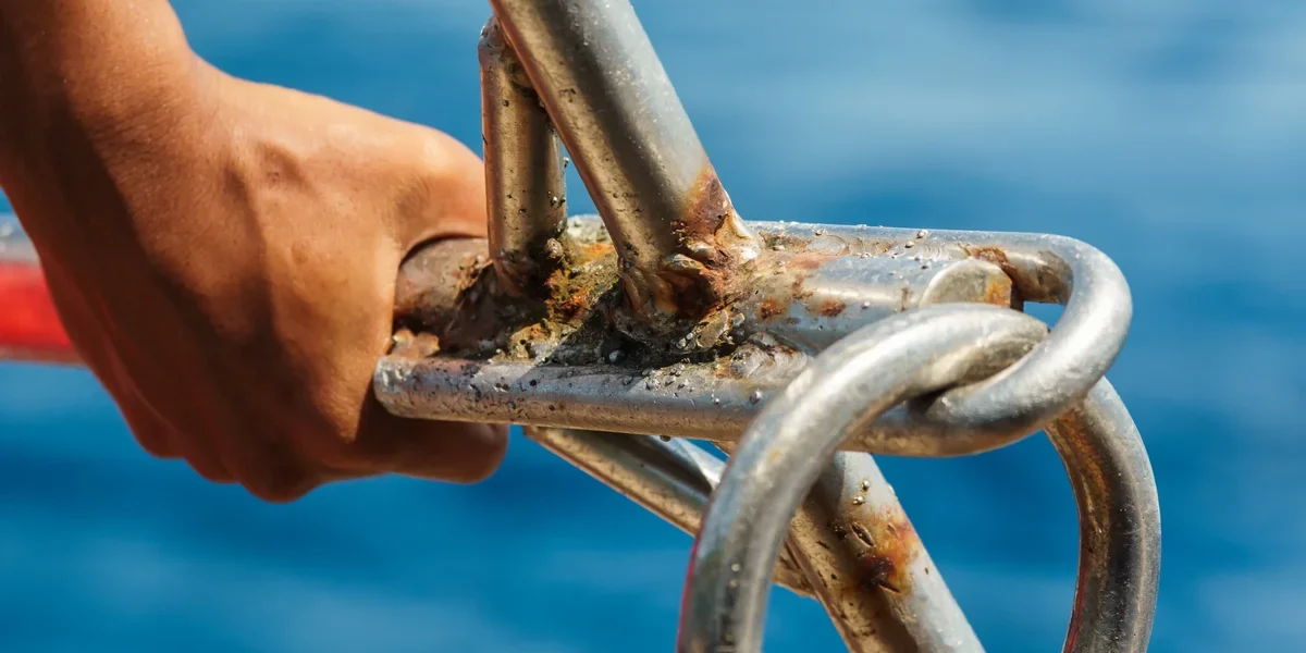
Corrosion failure is the leading cause of infrastructure downtime. To ensure longevity, you must demand hot-dip galvanizing that meets ISO 1461 standards with a coating thickness exceeding 85 microns.
Ensure Hot-Dip Galvanizing Meets ISO Standards
In the utility sector, the difference between a 5-year lifespan and a 30-year lifespan often comes down to the galvanizing process. For arrowhead earth anchors and other ground hardware, you must strictly require compliance with ISO 1461 (Hot-dip galvanized coatings on fabricated iron and steel articles). This is non-negotiable. Unlike electroplating, which merely sits on the surface, hot-dip galvanizing creates a metallurgical bond—zinc alloys with the steel to form a series of hard, corrosion-resistant layers.
We have seen far too many failures caused by “paint-dipped” or thinly coated alternatives that rust through in a single season. Our manufacturing process utilizes leading hot-dip galvanizing technology to ensure a smooth, bright finish that strictly adheres to ISO 1461. This standard dictates the coating composition and mass, providing the baseline defense necessary for underground steel components constantly exposed to moisture and varying soil pH levels.
Check Coating Thickness for Corrosion Protection
Compliance with ISO 1461 is the legal requirement, but the actual micron thickness is your physical insurance policy. Industry averages often hover near the minimum allowable limits to save costs, leaving anchors vulnerable in aggressive soils. You need to verify that the mean coating thickness significantly exceeds these baselines.
To guarantee maximum durability, we enforce a rigorous standard where our mean coating thickness consistently exceeds 85 microns. This heavier layer provides a substantial reservoir of zinc that will sacrificially corrode to protect the underlying steel, significantly extending the service life of the anchor. When procuring, request coating thickness test reports (gauging per IEC 120 or equivalent) to confirm you aren’t receiving the industry minimum.
- Minimum Baseline: ISO 1461 requirements (typically ~45-85 microns depending on steel thickness).
- Rax Power Standard: Mean coating thickness exceeding 85 microns for superior resistance.
- Verification Method: Magnetic thickness gauge testing conducted in-house.
Implement Routine Visual Inspections for Damage
Even the best galvanizing can be compromised if the coating is physically damaged during handling, transport, or installation. Once the zinc layer is breached, rust will spread rapidly from the exposed steel. A robust Quality Control (QC) protocol is essential before the anchor ever enters the ground.
We mitigate this risk through a double-review process where 100% of products are inspected twice before packaging. Our dedicated 10-person QC team monitors every production stage, specifically looking for nicks, scratches, or transport abrasions that expose bare metal. Before deployment, your team should perform a quick visual scan: reject any unit showing rust-colored spots or flaking coating, as these indicate immediate failure points in the field.
Never attempt to “touch up” damaged galvanizing with standard spray paint in the field. Standard paints do not offer the sacrificial protection of zinc and will trap moisture against the steel, accelerating corrosion. Damaged anchors must be replaced or professionally re-galvanized.
Conclusion
Driving arrowhead anchors requires precision. Loose topsoil causes deviation. Hard soil demands pilot holes. We see dealers skip proof load testing. This creates liability on large commercial projects. Our engineering team sees these failures weekly. Ignoring soil composition is the fastest way to compromise holding capacity. Your installation method dictates the structural integrity of the entire tie-back system. Treat every step as non-negotiable.
- Verify shaft integrity before deployment
- Drive the anchor deep and straight
- Remove the drive rod without displacement
- Conduct proof load testing procedures
Frequently Asked Questions
What is an arrowhead earth anchor?
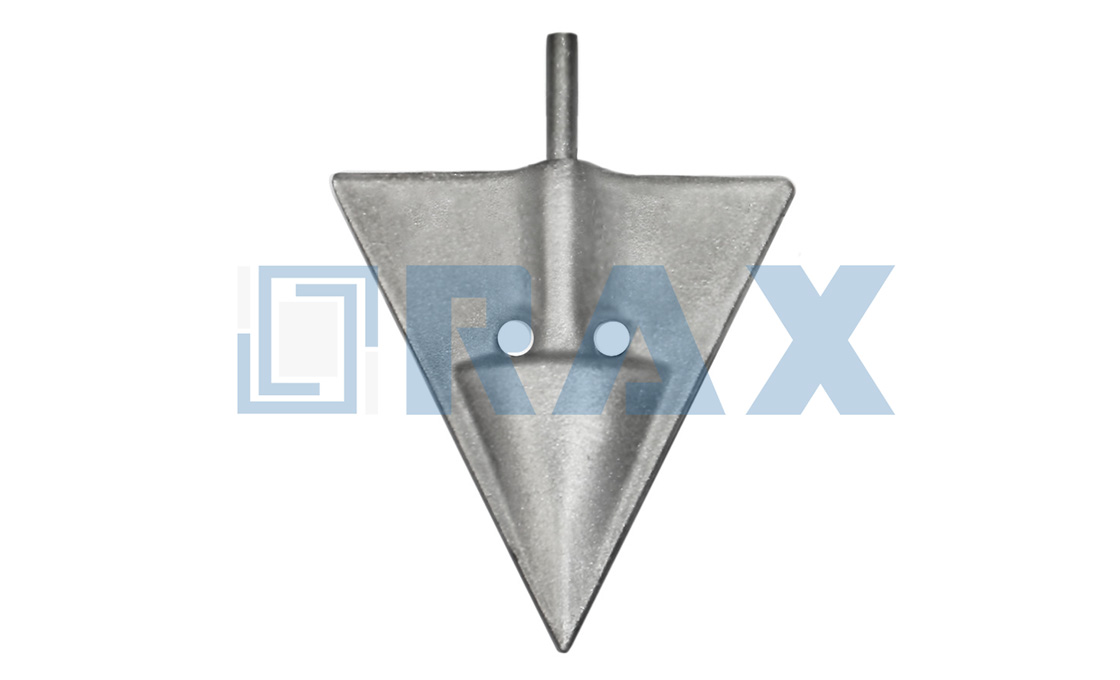
An arrowhead earth anchor is a type of helical pile featuring a pointed, conical tip designed to penetrate soil efficiently. It typically includes one or more helical flights that provide holding capacity by engaging with the surrounding ground. This design allows for rapid installation and high load-bearing performance in various soil conditions.
Which soil types suit arrowhead anchors best?
These anchors perform exceptionally well in dense clay, sandy loam, and compacted fill materials due to their penetrating tip. They can also be effective in rocky soils if the tip is sufficiently hardened to break through obstructions. However, extremely loose sand or highly organic peat may require specialized designs or larger surface areas for adequate holding power.
How do arrowhead anchors differ from duckbill anchors?
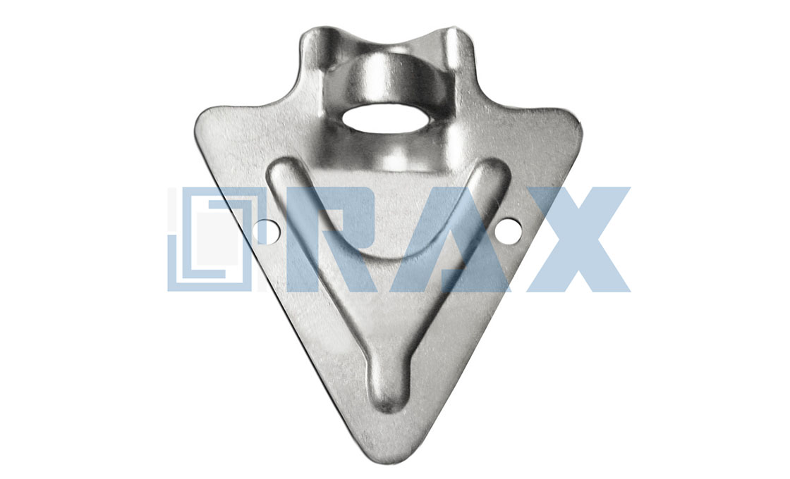
Arrowhead anchors feature a sharp, pointed tip for easy penetration, whereas duckbill anchors have a flat, hinged plate that opens after insertion. The arrowhead design is generally preferred for harder soils or where minimal disturbance is required during installation. Duckbills are often used in softer, looser soils where immediate expansion provides better grip.
How is load capacity determined for these anchors?
Load capacity is primarily determined by the diameter and pitch of the helical flights, as well as the soil’s shear strength. Engineers calculate this based on the total surface area of the flights in contact with the soil. In-house load testing per standards like IEC 120 helps verify these theoretical calculations against actual field performance.
Are arrowhead anchors suitable for solar foundations?
Yes, they are widely used in solar PV foundation systems due to their quick installation and high stability. Their ability to provide deep anchorage makes them ideal for resisting uplift forces from wind loads on solar panels. Many manufacturers, including Raxpower, offer specialized designs optimized for renewable energy infrastructure requirements.