
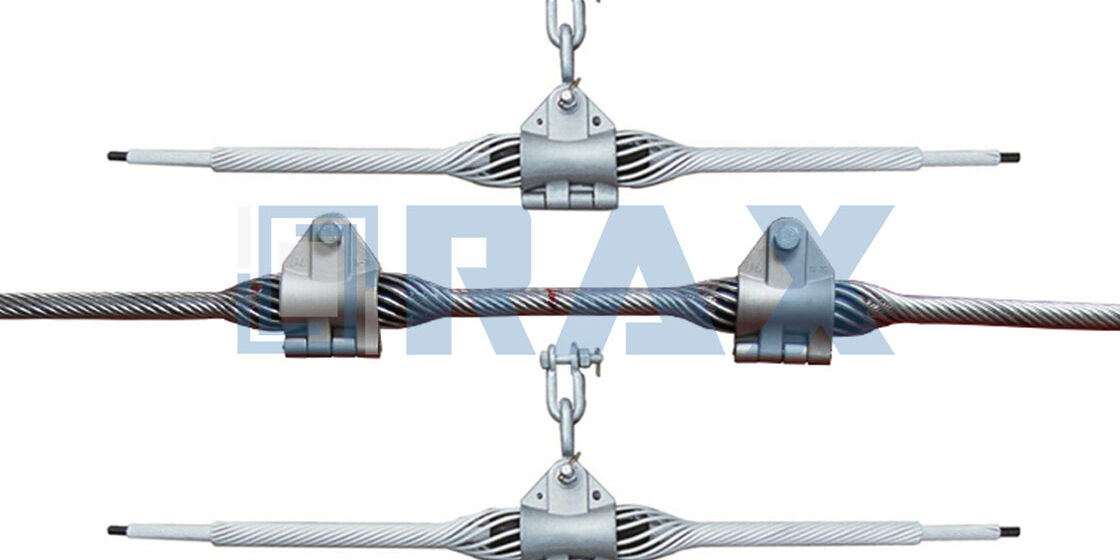
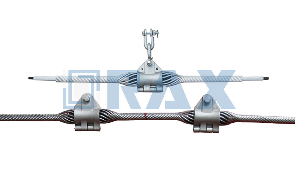
Standard suspension clamps concentrate stress on a single contact point, which inevitably crushes the outer sheath of ADSS cables or accelerates fatigue in OPGW strands. The armor grip suspension clamp solves this by using preformed armor rods that wrap around the cable to distribute mechanical loads evenly. This design prevents the localized damage that leads to premature failure in transmission networks.
To mitigate these localized stress points, engineers must look beyond traditional designs. This necessity drives the adoption of advanced gripping technologies that prioritize cable integrity.
Why Armor Grip Beats Standard Clamps
Armor grip systems fundamentally outperform standard bolted clamps by converting point-load stresses into uniform radial pressure, significantly extending the service life of sensitive ADSS and OPGW cables.
Mechanical Grip Strength and Load Distribution
The critical failure mode in traditional suspension systems is the concentration of mechanical load at a single point. Standard bolted clamps apply high compressive force in a narrow band, which creates stress peaks that can deform the conductor geometry and crush the internal core of fiber optic cables under heavy ice or wind loads. In contrast, the helical geometry of armor grips distributes the tensile load over a much greater surface area, effectively turning a suspension point into a support zone. This dispersion minimizes the risk of localized deformation and maintains the circular cross-section of the cable, which is essential for preserving optical performance.
Dimensional precision in preformed line products is the critical factor that enables effective load distribution across the conductor. Rax Power’s strict 1mm tolerance standards, derived from steel cross-arm automation capabilities, ensure that the grip creates a uniform shell around the conductor. This precision eliminates the play found in lower-quality cast alternatives, ensuring that the mechanical grip remains consistent even as the cable expands and contracts with temperature fluctuations.
Cable Surface Protection and Abrasion Resistance
While static load support is vital, the dynamic interaction between the hardware and the cable surface poses a greater long-term risk to utility assets. As cables sway in the wind, rigid clamps can act as fulcrums, grinding against the jacket sheath and causing abrasion that eventually breaches the cable’s water-blocking protection. Armor grips act as a sacrificial buffer, absorbing the kinetic energy of movement without allowing hard metal-to-metal contact with the conductor itself. The pliable nature of the grip maintains a constant tension that holds the cable securely without the gouging or biting associated with tightened bolts.
Corrosion resistance is not merely a cosmetic feature but a functional requirement to prevent abrasive damage to cable jackets. Surface roughness on suspension hardware accelerates this wear, grinding against the sheath during dynamic movement. By ensuring a smooth, bright finish, the hardware remains non-marring, effectively preventing the acceleration of abrasion and protecting the cable from mechanical degradation over its lifespan.
Vibration Damping Performance Metrics
Aeolian vibration—the high-frequency, low-amplitude wind-induced oscillation—is the leading cause of fatigue failure in overhead lines. Standard rigid suspension clamps create a “hard node” where vibration is abruptly halted, causing significant bending strain and fatigue at the exit point. Armor grip designs inherently function as vibration dampers. The layered, spiral structure absorbs and dissipates vibrational energy along the length of the rods, effectively detuning the suspension point and reducing the amplitude of vibration before it can damage the cable core.
Quantifying this protection requires rigorous testing against industry fatigue standards. We subject our preformed assemblies to in-house load and gauge testing compliant with IEC 120 to verify their self-damping characteristics. Our data indicates that systems utilizing these spiral formations show a marked reduction in strain levels compared to bolted counterparts. For projects in regions with high wind exposure, such as the open terrains of South America or Russia, this vibration attenuation is not a luxury but a requirement for maintaining grid reliability and preventing premature outages.
Key Specs and Engineering Features Explained
Material Composition and Structural Integrity
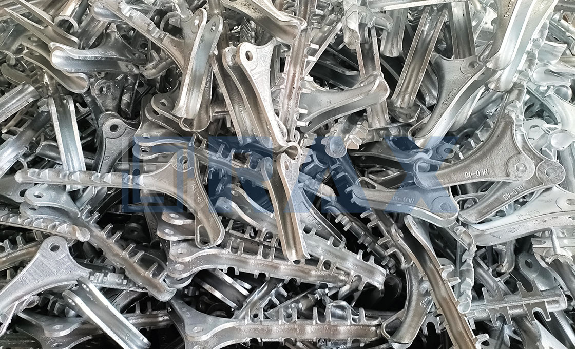
Internal grain structure optimization through hot-forging provides superior tensile strength compared to traditional casting methods. Rax Power utilizes this process for critical load-bearing components to ensure higher fatigue resistance.
Structural integrity in transmission hardware is primarily determined by the manufacturing method used to refine metal grain flow. While this process optimizes main components to withstand dynamic loads, the performance of specific fasteners such as U-bolts and eye bolts depends on rigorous material selection. These components require high-grade steel with defined yield strength and elongation percentages to maintain the necessary clamping force, ensuring the assembly remains secure despite the stresses induced by thermal expansion.
Galvanization Metrics and Corrosion Resistance
Corrosion protection is not merely cosmetic; it is a critical calculation of service life and Total Cost of Ownership (TCO). Engineering specifications must mandate compliance with ISO 1461 standards for hot-dip galvanizing. The baseline protection level typically requires a mean coating thickness exceeding 85 microns. This specific density is essential to safeguard the base metal against atmospheric oxidation, industrial pollutants, and soil acidity over multi-decade deployment cycles.
Buyers should scrutinize the galvanizing finish for uniformity. A smooth, bright finish indicates proper pre-treatment and dipping temperature control, which minimizes the risk of flaking or chipping during transport and installation. Rough, inconsistent galvanizing often signals poor bath chemistry control, leading to premature rust spots—specifically at threaded areas where the coating thickness is hardest to maintain. In coastal or industrial zones with high corrosivity categories (C4 or C5), demanding coating thickness verification via magnetic induction gauges is a standard quality assurance protocol before batch acceptance.
Dimensional Precision and Automation
The reliability of an overhead line system depends heavily on the cumulative fit of thousands of individual components. Dimensional deviation in a single cross arm or brace can propagate through the structure, causing misalignment that puts undue stress on bolts and insulators. High-volume production utilizing automated and semi-automatic machinery is required to achieve the strict tolerances necessary for modern infrastructure. For critical components like steel cross arms, engineering tolerances should be held within a strict 1mm range to ensure seamless assembly on the pole.
- Automated Punching & Drilling: Ensures hole diameters and spacing are consistent across batches, eliminating the need for field reaming which compromises structural integrity.
- Hot-Forging Tolerance Control: Guarantees that shank diameters and radii match mating hardware exactly, distributing load evenly rather than concentrating stress on a single point.
- Bolt Consistency: Thread rolling must be precise to ensure full engagement with nuts, preventing stripping under high-torque installation.
Verification and Load Testing Standards
Reliance on supplier declarations is insufficient for mission-critical infrastructure. Technical documentation must provide evidence of rigorous load testing and gauge testing conducted in-house. Protocols such as IEC 120 offer standardized methods for verifying the mechanical performance of suspension and tension hardware. A competent quality protocol involves a double-review process where 100% of products undergo dimensional and visual inspection before packaging, rather than relying on statistical sampling methods (AQL) which may allow defects to slip through.
Certification from third-party entities like SGS serves as a validation of these internal processes. However, the core engineering value lies in the factory’s capability to simulate actual field conditions—such as combined load tests (tensile, compression, and shear)—to verify that the safety factor meets the design requirements. For projects in regions with unique regulatory frameworks, such as the specific utility standards in South America or Southeast Asia, the test reports must explicitly demonstrate compliance with those local codes.
Choosing the Right Clamp for Your Needs
ADSS vs. OPGW Selection Criteria
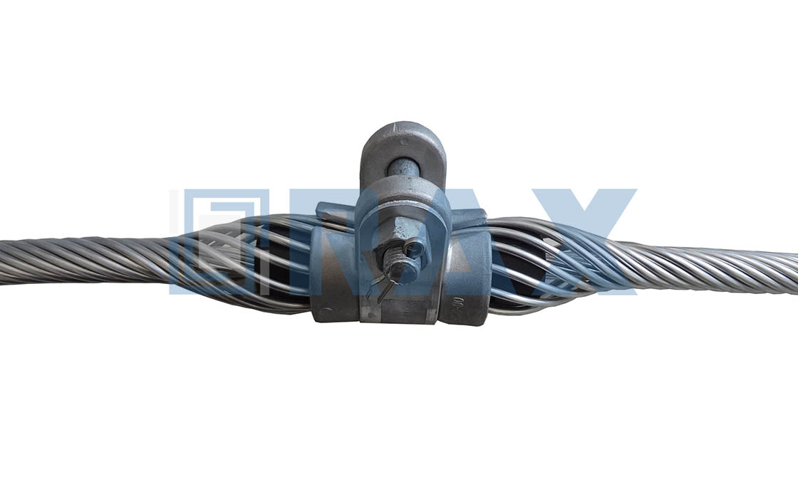
The primary technical differentiator in clamp selection is the dielectric requirement of the cable. ADSS (All-Dielectric Self-Supporting) cables contain no metallic components, making them highly susceptible to electric field-induced damage at suspension points. Consequently, selecting a preformed clamp for ADSS requires specialized aluminum-clad and rubber armoring strips to distribute surface pressure evenly. In contrast, OPGW (Optical Ground Wire) contains a central stainless steel tube or armor wires that bear the mechanical tension. For OPGW applications, standard galvanized or ACSR (Aluminum Conductor Steel Reinforced) grips are sufficient because the metallic core handles the load, reducing material costs without compromising structural integrity.
- ADSS Requirement: Must use non-conductive, high-friction cushion grips to prevent dielectric breakdown under high-voltage electric fields.
- OPGW Requirement: Standard metallic or galvanized dead-end grips effectively manage the load while providing necessary abrasion resistance.
Mechanical Span and Angle Considerations
Span length dictates whether a cable needs an intermediate suspension clamp or a heavy-duty dead-end anchor. For spans exceeding 300 meters, even moderate wind loads create significant lateral tension. Engineers must calculate the vertical angle between poles; a pole line deviation greater than 25 degrees typically requires a specialized multi-grip suspension clamp rather than a standard single-arm unit. Using a standard clamp on a high-tension angle creates excessive point-load friction, which will eventually fatigue and snap the internal fiber optic buffer tubes, leading to signal loss long before the external cable breaks.
Do not mix galvanized clamps with aluminum-clad grips on the same span. Mixing dissimilar metals accelerates galvanic corrosion at contact points, significantly shortening the lifespan of the entire line installation.

How to Install Armor Grip Properly
Improper installation is the primary cause of armor grip failure. Precise centering and maintaining the lay direction of the preformed rods are non-negotiable to ensure load distribution and prevent cable fatigue.
Pre-Installation Verification
Before the preformed rods touch the conductor, verify that the cable diameter matches the armor grip specification. A mismatch of even 1-2mm can prevent the helical rods from seating correctly, leading to uneven pressure distribution. Additionally, inspect the cable jacket for existing nicks or abrasions; installing a grip over damaged insulation merely masks a failure point that will worsen under dynamic load.
Ensure the installation area on the cable is free of moisture, ice, or debris. Even a thin layer of ice can prevent the grip from achieving the necessary friction coefficient, potentially causing slippage during wind-induced vibration.
Step-by-Step Installation Procedure
The installation of preformed armor grips requires a systematic approach to ensure the helical structure integrates with the cable geometry. Unlike bolted clamps, these rely on elastic deformation to maintain grip force.
📋 Actionable Steps
- Step 1: Centering: Locate the exact suspension point on the pole hardware. Mark the center position on the cable jacket using non-permanent tape or a marker. This mark aligns with the center of the preformed rods.
- Step 2: Positioning the Inner Rod: If installing a suspension set, position the inner rod first. Align the center of the rod with the marked center point on the cable. Do not rotate the rod against the cable lay.
- Step 3: Winding the Preformed Rods: Starting from the center, apply the preformed rods by pushing them along the cable lay direction. Work progressively outward from the center towards the end. This prevents bunching and ensures the rods close uniformly around the cable circumference.
- Step 4: Closing the Ends: Once the main body is seated, close the end ears or keeper rods. These should snap shut firmly without the need for excessive force. If they do not close easily, the rod may be undersized for the cable diameter.
- Step 5: Hardware Integration: Place the assembled suspension clamp body over the installed armor rods. Ensure the armor grip sits centrally within the clamp’s suspension groove to avoid point-loading the cable.
Addressing Layered Installations
In repair scenarios or high-stress applications, armor grip suspensions can be installed over preformed armor rods. When layering, it is critical to ensure the first layer is perfectly smooth with no protruding strands. Any gap or high point in the base layer will create a pressure point that can cut into the outer armor rod layer or the cable jacket during thermal expansion and contraction cycles.
Final Visual Inspection
Once installed, perform a final visual check. There should be no gaps between the rod and the cable surface exceeding 1mm along the main contact section. The rods must appear to flow smoothly with the cable’s contour. Any visible “cocking” or uneven spacing indicates a mismatch in size or an installation error that requires immediate correction.

Validating Safety and Performance Before Use
Safety validation requires verifying certification compliance (e.g., IEC 61952) and conducting rigorous load testing to ensure the clamp can safely handle extreme mechanical stress and environmental factors before grid energization.
Pre-Energization Inspection Protocols
Before an overhead line is commissioned, the integrity of suspension hardware must be validated through a systematic inspection process. This phase acts as the final quality gate, catching manufacturing defects or handling damage that occurred during logistics. For preformed armor rods and suspension grips, technicians must visually inspect the helical rods to ensure the inner layer has no kinks or gaps that could compromise the grip on the conductor or optical cable.
Dimensional verification is equally critical. The tolerance between the grip and the cable diameter must fall within the strict ranges defined by engineering specifications (typically +/- 0.5mm to 1.0mm depending on the application). An oversized grip leads to slippage under load, while an undersized grip can crush the cable jacket or damage the aluminum strands of an ACSR conductor.
- Visual Defect Check: Inspect for zinc spalling, sharp edges, or misaligned helical formations that could induce stress concentrations.
- Fit-Up Verification: Confirm that the preformed rods close uniformly around the cable without requiring excessive force or leaving visible gaps.
- Component Compatibility: Ensure all ancillary fittings (bolts, nuts, washers) are the correct grade and size for the associated suspension clamp body.
Mechanical Load Testing Metrics
Rigorous mechanical testing is the only reliable method to validate the rated strength of pole line hardware. Standard industry practice dictates that a percentage of the batch—often 1% to 5% or a specific number per lot—undergoes destructive or proof load testing. The objective is to verify that the hardware can withstand the calculated Maximum Working Load (MWL) with a defined Safety Factor (typically 2.5 to 3.0 times the MWL for transmission hardware).
For suspension clamps specifically, slip tests are mandatory. The assembly must be subjected to increasing tensile load to verify that the grip mechanism holds the cable firmly up to the point of failure of the hardware itself, rather than slipping. Any slip observed below the rated slip load threshold results in immediate rejection of the batch.
- Proof Load Test: Apply a load equal to the Working Load Limit (WLL) multiplied by the safety factor (e.g., 2.5x or 3.0x) for a specified duration to check for permanent deformation.
- Slip Load Test: Measure the load at which the cable begins to slide within the grip; this must exceed the manufacturer’s specified minimum slip resistance.
- Residual Strength Check: For vibration dampers and grips, ensure that after vibration fatigue testing, the unit retains a sufficient percentage of its original mechanical strength.
Corrosion Protection and Material Compliance
Environmental degradation is a leading cause of hardware failure in coastal or industrial zones. Validating corrosion resistance involves checking the galvanization quality against standards such as ISO 1461 or ASTM A153. The coating must be smooth, continuous, and free of bare spots. Thickness measurements should be taken at multiple points to ensure the average micron thickness meets the project specification requirements for the expected service life.
Material composition is the foundation of performance. For critical load-bearing components like the suspension clamp body or bolts, material test certificates (MTCs) must be cross-referenced with the physical components. This ensures that the correct grade of ductile iron or steel is used, preventing brittle fracture under extreme cold conditions or impact loads.
- Coating Uniformity: Verify there are no flux deposits or ash inclusions on the zinc surface that could harbor moisture.
- Chemical Analysis: Validate carbon and silicon content in castings to ensure optimal mechanical properties and weldability if field modifications are required.
- Adhesion Test: Perform a knife test to ensure the galvanized coating adheres firmly to the base metal without flaking.

Routine Maintenance for Longer Clamp Life
Proper lifecycle management of suspension hardware hinges on a disciplined, three-pillar approach: rigorous zinc-coating verification, tension monitoring, and localized environmental assessment.
Extending the operational lifespan of armor grip suspensions requires moving beyond reactive repairs to proactive, data-driven maintenance. In the high-stakes environment of overhead transmission lines, the integrity of the preformed hardware directly correlates with the longevity of the ADSS or OPGW cables it supports. We have observed that grid operators who prioritize a overall inspection strategy—combining metallurgical checks with mechanical tension reviews—consistently experience fewer unscheduled outages related to cable abrasion or mechanical fatigue.
Galvanization Integrity Inspection Schedules
The primary defense against premature failure in pole line hardware is the metallic coating applied during manufacturing. While modern automated facilities utilize ISO-compliant hot-dip galvanizing to deliver mean coating thicknesses exceeding 85 microns, field conditions can slowly erode this protective barrier. Inspections should be structured around local climate severity, focusing on identifying early-stage oxidation or physical damage to the zinc layer.
- Annual Visual Audits: Conduct close-up inspections of the suspension clamp and armor rods for any visible chipping, peeling, or white rust formation, particularly in areas exposed to high humidity or coastal salt spray.
- Coating Thickness Verification: Utilize magnetic induction gauges to verify that coating thickness has not dropped below critical thresholds in high-wear zones, ensuring the barrier remains effective against electrolytic corrosion.
- Post-Installation Confirmation: Immediately following any tensioning or repair work, inspect contact points where metal-to-metal friction may have compromised the initial factory-applied finish.
Preformed Component Tension Monitoring
The functionality of a preformed armor rod relies entirely on its precise helical wrap around the cable sheath. Over time, dynamic wind loads, extreme temperature fluctuations causing thermal contraction/expansion, and ice loading can alter the tension profile of these components. If the preformed element becomes too loose, it loses its anti-vibration capabilities; if it is overtightened during improper adjustments, it risks crushing the optical fibers inside.
Maintenance teams should establish a routine to monitor the tension states of the system. This involves evaluating the physical alignment of the preformed wire wraps and ensuring they maintain uniform pressure across the entire circumference. Our engineering team notes that regular tension checks are vital to prevent the “work-hardening” of aluminum wires, which can lead to micro-fractures if the mechanical stress is allowed to build up unchecked over several years of service.
Environmental Degradation Assessment Factors
No two transmission corridors experience identical environmental stressors. A thorough maintenance roadmap must include an assessment of external factors that accelerate wear. Industrial pollution, such as sulfur dioxide from nearby manufacturing plants, creates acidic environments that aggressively attack galvanized steel. Similarly, heavy vegetation growth can introduce biological moisture retention and physical abrasion from branches rubbing against the suspended cables.
By systematically addressing galvanization health, maintaining optimal preformed tension, and adapting inspection frequency to local environmental hazards, utilities can significantly extend the lifespan of their overhead line infrastructure. This disciplined approach transforms hardware maintenance from a cost center into a reliable asset protection strategy.
| Maintenance Focus | Specific Action | Risk Addressed | Outcome |
|---|---|---|---|
| Alignment Verification | Check positioning at designated suspension points | Uneven stress distribution | Optimal performance stability |
| Tension Monitoring | Review assembly tension and security of fittings | Vibration-induced fatigue | Extended cable and clamp lifespan |
| Armor Rod Inspection | Ensure preformed armor rods remain evenly wrapped | Cable wear and tear | Enhanced protection against abrasion |
| System Evaluation | Assess overall mechanical stress distribution | Reduced lifespan of cables | Reliable long-term operation |
Conclusion
Properly selecting Armor Grip suspension clamps dictates the structural integrity of your ADSS cable installations. Standard clamps often fail under dynamic wind loads, causing abrasion and eventual fiber breakage. Our engineering team manufactures high-tensile formed wire components that distribute mechanical stress evenly across the cable jacket. This design prevents localized crushing while maintaining necessary tension levels. You must verify galvanization thickness and preformed wire alignment before deployment. Incorrect installation accelerates wear patterns that void manufacturer warranties.
- Confirm load ratings match your specific span requirements.
- Request technical drawings from our engineering support team.
- Validate torque specifications for all mounting hardware.
Frequently Asked Questions
What is an armor grip suspension?
An armor grip suspension is a specialized hardware component used to secure and support optical fiber cables, such as ADSS or OPGW, on transmission poles. It provides mechanical strength while protecting the delicate cable sheath from damage during installation and operation. This device acts as both a tension anchor and a vibration damper in overhead line systems.
What standards govern selection?
Selection typically follows IEC 60794 and IEEE standards for optical fiber cables and their accessories. Engineers must match the grip’s rated tensile strength to the cable’s maximum allowable tension (MAT). Proper sizing is critical to ensure the hardware can withstand expected load conditions without slipping or causing damage.
What about corona discharge risks?
High-voltage applications require grips with smooth, rounded edges to minimize electric field concentration. Materials with high dielectric strength help prevent corona discharge and electrical tracking along the surface. Selecting hardware certified for specific voltage levels ensures safety and compliance with utility grid requirements.
What certifications do you hold?
Our products undergo comprehensive testing including SGS verification and compliance with ISO 1461 for hot-dip galvanizing. We also conduct in-house load and gauge testing per IEC 120 standards to verify structural integrity. These certifications ensure our hardware delivers consistent quality and safety for global utility infrastructure.
Do you offer custom molds?
Yes, we provide OEM/ODM services to create custom suspension solutions based on specific project drawings or samples. Our engineering team utilizes advanced mold development techniques to tailor hardware dimensions and specifications. This flexibility allows us to meet unique technical requirements for specialized power transmission projects worldwide.