
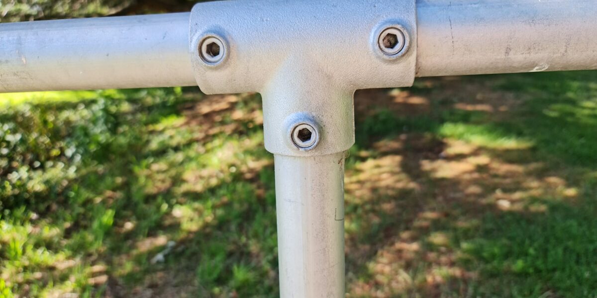
Offsetting crossarms on utility poles requires more than just a sturdy bracket; it demands precision manufacturing to ensure the mounting hardware aligns perfectly under load. Getting the alley arm tolerance wrong in the fabrication phase turns a simple installation into a field modification nightmare, particularly when dealing with the strict clearance requirements of European distribution grids. A galvanized coating thickness exceeding 85µm is critical for meeting corrosion standards, yet this thickness introduces variables that can easily throw off critical thread fits. Understanding these specific tolerances before you place an order prevents the costly downtime associated with non-fitting components.
This article details the European regulatory compliance framework, specifically how EN ISO 1461 galvanizing standards interact with dimensional tolerance classes. We also cover the critical load testing metrics you need to verify, ensuring that the hot-dip galvanizing process hasn't compromised the structural integrity of the steel threads or the load-bearing weld points. These are the technical checkpoints that separate a compliant installation from a failed audit.

European Regulatory Compliance Framework
Compliance is an integrated engineering framework, not a checkbox. Mapping overlapping EN and IEC protocols guarantees structural reliability and accelerates utility vendor qualification.
Utility procurement in Europe does not leave room for dimensional guesswork or corrosion shortcuts. When project planners align alley arm specifications across EN 50119, EN 1090, and ISO 1461, the immediate priority shifts from component sourcing to systemic risk mitigation. Grid operators demand hardware that maintains rigid alignment under severe thermal cycling and dynamic wind shear, making regulatory literacy the primary gatekeeper for tender approval.
The intersection of EN 1090 execution classes and EN 50119 overhead line requirements dictates how strictly manufactured brackets must interface with existing pole infrastructure. Misinterpretation of allowable deviation bands routinely triggers expensive field rework, particularly when pre-fabricated cross arms encounter misaligned mounting points. Procurement teams must verify that geometric variances remain locked within approved structural thresholds before authorizing bulk production runs.
In our experience engineering hardware for European grid expansions, we consistently find that generic tolerances fail to satisfy utility-grade bracing mandates. Automated machining eliminates manual variance during mass production, guaranteeing that every bracket meets identical geometric parameters. We recommend specifying execution class certification upfront to prevent installation delays and expedite engineering sign-off.
Corrosion Protection Benchmarks Under ISO 1461
Hot-dip galvanizing standards dictate long-term asset viability in aggressive atmospheric zones. Procurement planners frequently mistake minimum local coating thickness for comprehensive structural coverage, creating a false sense of security regarding material lifespan. The ISO 1461 framework evaluates the average zinc layer across multiple measurement points, which directly determines uniform protection against salt spray, industrial pollutants, and freeze-thaw degradation.
When manufacturers execute continuous immersion cycles, the resulting intermetallic zinc-iron bond delivers superior adhesion compared to mechanically sprayed alternatives. Our quality assurance protocols continuously verify that batch samples maintain consistent protective density, ensuring decades of maintenance-free operation in coastal or alpine utility corridors.
Mechanical Load Validation Through IEC Protocols
Static and dynamic load verification remains the definitive filter between standard industrial fasteners and utility-grade transmission components. IEC testing frameworks simulate years of operational stress by cycling forged joints through repeated tension, shear, and torsional forces. These protocols confirm that structural connections maintain rigidity when subjected to sudden conductor slapping or heavy ice accumulation without plastic deformation.
We consistently emphasize that theoretical yield strength never translates directly to field performance without empirical cycle testing. Rigorous in-house gauge validation combined with systematic dual inspection checkpoints eliminates latent manufacturing defects before dispatch. This disciplined approach guarantees that every delivered unit sustains the calculated safety margins required by regional grid operators.
| Regulatory Standard | Technical Requirement | Rax Power Specification | Engineering Advantage |
|---|---|---|---|
| EN ISO 1461 / ASTM A123 | Minimum coating thickness for atmospheric corrosion resistance | Hot-dip galvanized finish exceeding 85 microns mean thickness | Ensures long-term structural integrity in harsh European climates |
| EN 1090 / EN 50119 | Strict manufacturing tolerances for pole line hardware alignment | Automated production guaranteeing ±1mm dimensional accuracy | Eliminates on-site installation misalignment and ensures rigid bracing |
| IEC 120 / EN 50119 | Verification of static and dynamic load capacities | Rigorous in-house load and gauge testing with 100% double-review inspection | Validates fatigue resistance and prevents premature failure under ice or wind loads |
| Utility Grade Execution Class | High-strength material specifications exceeding casting limits | Hot-forged triple-eye rods and structural components | Delivers higher tensile strength and impact resistance for critical grid infrastructure |
| SGS Verified / ISO Framework | Comprehensive vendor qualification and compliance auditing | Full ISO documentation package provided with bulk orders | Accelerates project approval and meets stringent European utility procurement rules |
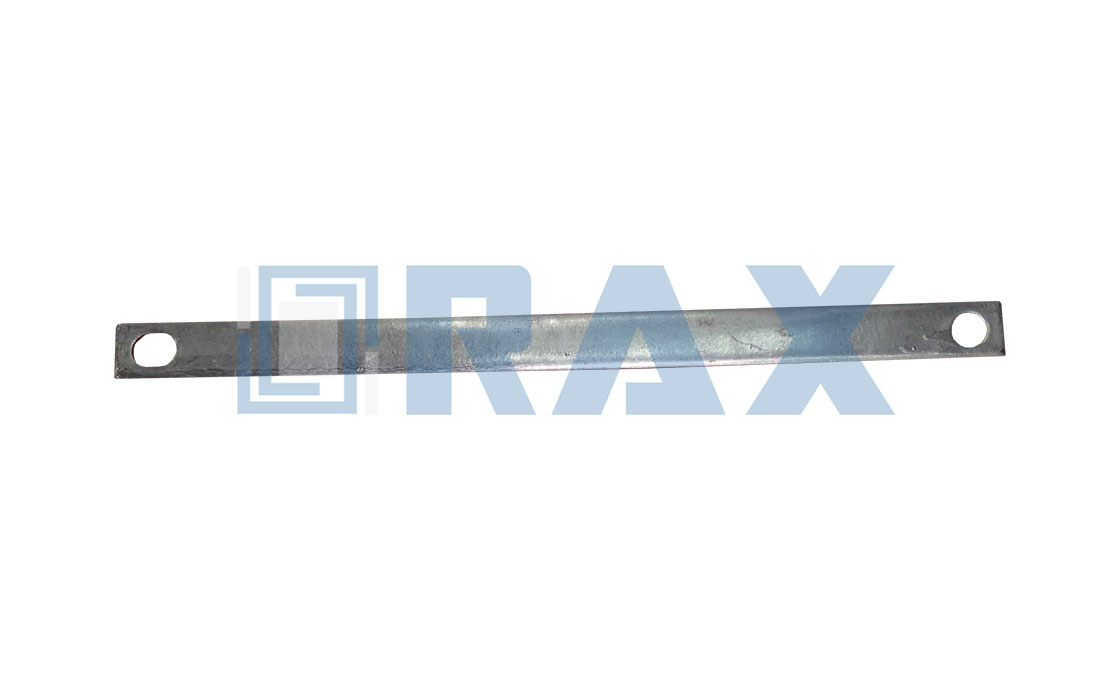
Dimensional Tolerance Classifications
Dimensional tolerance classifications dictate whether factory-fabricated alley arms and braces will mate seamlessly with legacy pole hardware or cause critical installation delays. When manufacturing tolerances for length, hole diameter, and mounting angles exceed industry baselines, contractors face structural misalignment, stripped fastener threads, and compromised joint rigidity. High-precision automated production maintains a strict dimensional variance of ±1mm across primary axes, ensuring consistent bolt seating and eliminating on-site cutting or field drilling.
Length and Axis Alignment Tolerances
Standard cast components often carry length variances between ±2.0mm and ±3.0mm, which compounds when multiple clevis pins or lag screws are engaged along a single arm span. Precision-manufactured steel cross arms and alley braces hold a strict ±1mm tolerance on all primary mounting axes. This range prevents cumulative gap errors that force installers to force-fit components, stripping bolt threads or warping the pole attachment points.
- Primary Span Variance: Held within ±1.0mm to guarantee parallel alignment with existing secondary racks and pole bands.
- Branch Arm Length: Standardized to ±1.0mm maximum deviation to maintain consistent insulator spacing and phase clearance across uneven terrain.
- Cumulative Tolerance Buildup: Automated cutting and machining prevent the ±0.5mm per-component drift seen in manual fabrication, keeping total assembly length within ±1.0mm.
Hole Diameter and Fastener Seating Precision
The most frequent source of installation misalignment stems from oversized or irregularly punched fastener holes. When hole diameters drift beyond ±0.5mm from the nominal bolt size, lateral play develops at the pole attachment point. This play translates into wind-load induced vibration, accelerating fatigue failure at the weld toes of angle steel braces. CNC-punched holes maintain tight concentricity, allowing machine bolts and 1/2" lag screws to seat flush without requiring oversized shims or field reaming.
- Nominal Bolt Clearance: Punched holes sized to ±0.5mm tolerance over standard 3/8" or 1/2" fasteners to eliminate lateral play and distribute shear stress evenly.
- Pole Band Slot Alignment: Matched within ±0.5mm to ensure uniform compression across the band interface during tightening, preventing localized stress concentrations on the pole.
- Hole Edge Integrity: Automated punching with deburring protocols prevents burr migration into bolt threads, reducing installation torque variability by up to 15%.
Angular Bracket Precision and 45-Degree Bracing
Alley arms require rigid lateral support to counterbalance unidirectional line tension. Braces mounted at a 45-degree angle must maintain angular accuracy within ±0.5 degrees. Deviations in the bracket angle shift the load vector away from the pole’s centerline, creating torsional stress on the wood or composite pole. Hot-forged and CNC-bent bracket components preserve geometric integrity, distributing shear forces evenly across the welded lineman step and mounting flange.
- Brace Mounting Angle: Verified within ±0.5° to ensure load vectors align vertically with the primary crossarm axis, preventing pole lean under asymmetrical loads.
- Flange Coplanarity: Maintained to ±1.0mm flatness to guarantee full bearing surface contact against pole rails and angle steel, maximizing friction grip before torque application.
- Weld Joint Geometry: Angled brace connections feature controlled bevel tolerances to ensure continuous fillet welds, eliminating stress risers at the pole-arm intersection.
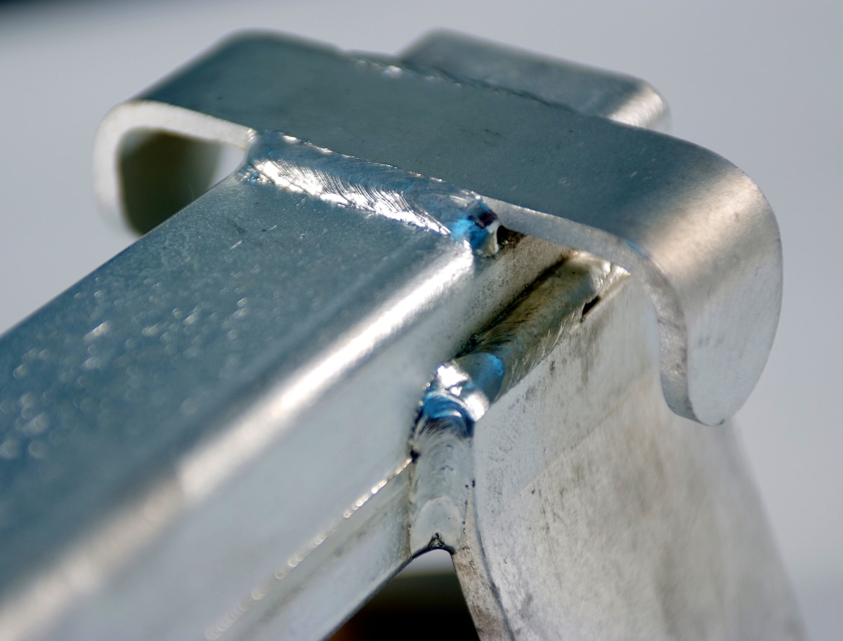
EN ISO Galvanizing Standards Compliance
EN ISO 1461 compliance guarantees structural corrosion protection only when combined with verified metallurgical adhesion and rigorous post-production inspection. Minimum thickness thresholds alone do not predict service life in aggressive environments.
Procurement engineers frequently misinterpret EN ISO 1461 specifications as a simple surface coverage checklist. In reality, the standard defines a minimum mean coating thickness that varies by steel section size. When manufacturers treat compliance as a passive outcome rather than an engineered process, premature white rust or localized pitting becomes inevitable during early field deployment.
Metallurgical Bonding Versus Surface Deposition
Pure zinc plating offers zero structural corrosion resistance in marine or high-humidity utility networks. Hot-dip galvanizing requires controlled chemical reactions that form a graded zinc-iron alloy layer between the base metal and the outer pure zinc shield. This intermetallic bonding dictates whether the coating survives transport abrasion, torque-driven installation, and decades of thermal cycling.
Field data confirms that coating longevity correlates directly with alloy layer uniformity, not merely total weight per square meter. Operators utilizing automated temperature regulation during the immersion phase consistently achieve mean coating thickness values exceeding 85 microns. This margin safely clears regional utility minimums while providing a functional buffer against edge thinning and complex geometry shadowing.
Verification Protocols for Bulk Infrastructure Orders
Quality assurance teams typically deploy calibrated magnetic induction gauges at geometric stress concentrators, including bolt threads, bend radii, and flange edges. Measuring at these specific coordinates reveals coating thinning that occurs during mechanical handling. Cross-referencing these readings against independent SGS audit reports establishes a defensible chain of custody for project auditors.
Environmental Stress Tolerance and Service Life Prediction
European utility networks operate under severe thermal cycling and airborne salt contamination. Standard galvanized fittings that pass initial thickness checks frequently fail when subjected to repeated freeze-thaw expansion and contraction cycles. The absence of a continuous alloy barrier allows moisture penetration along micro-fractures, accelerating substrate oxidation.
Engineering specifications should mandate continuous surface integrity checks rather than isolated spot measurements. Smooth, bright finishes indicate proper flux activation and adequate dip residence times. When combined with rigorous load testing per IEC protocols, verified galvanizing layers maintain structural clamping force and electrical continuity throughout the expected infrastructure lifespan.

Load Testing Metrics And Safety Factors
Engineering resilience relies on verifying that minimum yield strength significantly exceeds operational loads to prevent plastic deformation under variable environmental stressors.
Dynamic vs. Static Load Assessment
Utility planners often face the misconception that hardware load ratings are purely static measurements based on the weight of conductors. In reality, side-mounted assemblies such as alley arms are subjected to complex cantilever forces where the primary stressor is dynamic. Wind loading, ice accumulation, and differential thermal expansion create rapidly shifting tension loads that far exceed the static weight of the lines. For instance, an alley arm supporting a heavy transformer bank must not only hold the static deadweight but also withstand the uplift and sway forces generated during high-wind events.
Structural integrity hinges on distinguishing ultimate failure thresholds from standard operating parameters. To mitigate these risks, modern pole line hardware is engineered with safety factors that accommodate both dynamic and static extremes under EN/IEC compliance frameworks. While the breaking load marks the point of structural failure, the proof load—typically defined as a standardized percentage of the breaking load per mechanical validation benchmarks—serves as the critical threshold for daily operation. Furthermore, high-quality manufacturing processes, particularly hot-forging components over casting methods, deliver superior fatigue resistance. This ensures the metal matrix can reliably absorb repeated dynamic stress cycles without initiating micro-fractures, thereby preventing catastrophic failure while maintaining alignment with rigorous coating thickness and load validation standards.
The Role of Bracing Angles and Material Integrity
The effectiveness of load distribution in side-mounted configurations is heavily dependent on the geometry of the bracing system. A standard rigid brace typically mounts at a 45-degree angle to convert horizontal tension into compressive forces on the pole. If the manufacturing dimensional tolerances are too loose, or if the alignment is off during installation, the load path is compromised. This misalignment can transfer shear stress to the connection bolts rather than tension to the brace, drastically reducing the assembly's effective load rating.
Material selection plays a pivotal role in maintaining these precise geometries under stress. Utilizing triple-eye rods and robustly welded helices ensures that the anchor points do not elongate or deform when tension is applied. Loose tolerances in these components create "play" in the system, which accelerates wear at the connection points during wind-induced vibration. Therefore, strict adherence to dimensional limits is not merely a cosmetic requirement but a structural necessity that ensures uniform load distribution across the hardware and the utility pole.
Verification Protocols and Safety Margins
Verifying the claimed load capacity of pole line hardware requires rigorous testing protocols that simulate real-world conditions. In-house tension testing, conducted in accordance with established IEC standards, is essential for confirming that anchoring systems can hold their rated capacity without slippage. This verification process should measure the performance of the entire assembly—including the anchor, the rod, and the connection hardware—rather than testing individual components in isolation.
For bulk procurement, reliance on third-party verification such as SGS material certification adds a necessary layer of accountability. These audits confirm that the chemical composition of the steel and the physical properties of the galvanizing meet the required specifications. A comprehensive quality protocol involves a double-review process where every unit is gauged against approved templates before packaging. This level of scrutiny ensures that the safety factors engineered into the product are preserved from the production line to the installation site, ultimately protecting the grid from premature structural failures.

Coating Thickness Versus Fitting Tolerances
High-performance pole line hardware requires calculating "negative tolerance" in raw steel fabrication to ensure the final assembly fits precisely after the zinc coating is applied.
The engineering friction between coating longevity and dimensional fit is a primary source of field failures. In the rush to maximize corrosion resistance—particularly for infrastructure facing harsh European winters—specifications often demand heavy galvanizing. However, buyers frequently overlook the physical reality that hot-dip galvanizing is a metallurgical bonding process, not a superficial paint application. It adds volume. If the manufacturing process does not proactively compensate for this zinc build-up, the "thicker" the coating, the less likely the hardware is to fit correctly during installation.
The Geometry of Zinc Buildup
To achieve a mean coating thickness exceeding 85 microns (compliant with ISO 1461), the zinc layer can physically add between 0.1mm and 0.15mm to the surface of a steel component. While this seems negligible on a large scale, it is critical for interfacing parts. For instance, when a U-bolt is galvanized, the bolt diameter increases, and the internal diameter of the corresponding nut decreases. If the raw steel is not "undersized" prior to galvanizing, the threads will bind, rendering the fastener useless.
- External Surfaces: Zinc adheres externally, increasing the overall footprint of the hardware. A bracket designed to fit into a 50mm slot must be manufactured at approximately 49.7mm raw steel to allow for the zinc expansion.
- Internal Threads: The zinc accumulates inside the thread roots. This requires "tapping" or "chasing" the threads after galvanizing to restore the pitch diameter, or using oversized nuts to match the coated bolts.
- Accumulation on Edges: Zinc naturally pools on corners and edges due to surface tension. A sharp 90-degree corner can become rounded and oversized, potentially interfering with mating flat surfaces.
Managing Tolerances in Structural Components
For structural assemblies like alley arms and crossarms, the interaction between coating thickness and fitting tolerance is even more complex due to the leverage forces involved. A standard tolerance of 1mm on a finished assembly is widely accepted for ensuring alignment, but maintaining this after galvanizing requires precision control of the raw material.
Achieving a 1mm post-galvanization tolerance implies that the cutting and drilling of the raw steel must be accurate to within a fraction of that, specifically accounting for the uniformity of the zinc flow. If a factory applies a thick, uneven coating to a bracket that was cut to nominal dimensions, the resulting variances can easily exceed the allowable 1mm limit. This causes "installation anxiety" where contractors find that mounting holes do not align with pole bands or that brace brackets cannot be seated flush against the crossarm.
Beware of suppliers who offer "extra thick" galvanizing without reducing the pre-galvanized dimensions of the hardware. This creates a "false positive" on quality—the coating looks good in the lab, but the hardware fails on the pole because the mounting holes are undersized or the bolts won't thread.
The "Oversize" Strategy for Reliable Assembly
The solution to this trade-off is not to reduce coating quality, but to adjust the "blank" dimensions. Experienced manufacturers implement a negative offset strategy during the fabrication phase.
- Pre-Galvanizing Offset: Drill holes larger and cut plates smaller than the final target dimension. For a 16mm bolt hole, a drill bit of 16.5mm or 17mm may be used to ensure the coated bolt passes through freely.
- Centrifugal Cleaning: For smaller fasteners, high-speed centrifuging is used immediately after dipping to remove excess zinc from threads before it hardens, preserving the tolerance without sacrificing corrosion protection on the body.
- Mating Component Pairing: Nuts and bolts should be galvanized together as a set to ensure the zinc buildup on the male thread matches the clearance on the female thread.
When evaluating suppliers, the question is not just "What is your coating thickness?" but "How do you adjust your pre-galvanizing tolerances to ensure the hardware fits in the field?" A failure to answer this with specific offset data indicates a high risk of installation delays and rework costs.
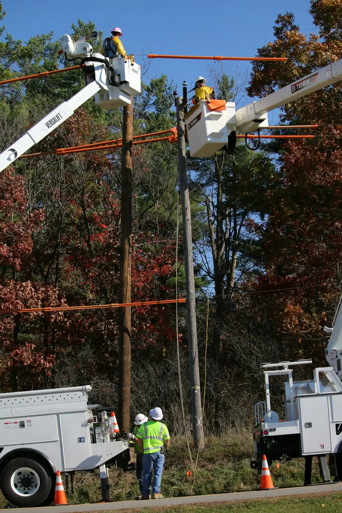
Installation Alignment Tolerances
Geometric Perpendicularity and Load Distribution
Installation alignment tolerances are critical for preventing uneven load distribution on pole line hardware. When mounting alley arms or crossarms, the primary requirement is achieving a perfect right angle (90 degrees) between the arm and the utility pole. Deviation from this perpendicular alignment introduces cantilever stresses that the mounting hardware—specifically lag screws and machine bolts—were not designed to sustain over long durations. If the arm is twisted or pitched relative to the pole, the connection points suffer from shear stress rather than pure tension, significantly compromising the mechanical stability of the overhead conductor.
To mitigate these risks, high-precision automated manufacturing processes enforce dimensional consistency. With a strict tolerance of 1mm on critical steel components, installers can trust that the hardware will sit flush against the pole surface without requiring shimming or forceful bending. This precision eliminates the anxiety regarding "loose fits" where mounting hardware fails to engage fully with the pole or the crossarm.
Angular Bracing Tolerances
Bracing systems, such as alley arm braces, rely heavily on specific angular geometry to function effectively as tension members. These braces are engineered to mount at a precise 45-degree angle relative to the pole and the arm. This specific angle is calculated to provide optimal triangulation, converting vertical loads into compressive forces that the steel angle can easily withstand.
- 45-Degree Mounting Angle: Braces must be installed at a 45-degree angle to maximize structural rigidity and prevent lateral movement of the crossarm.
- Hole Alignment: Alignment holes in the brace and the arm must align within 1mm to allow for the smooth insertion of machine bolts without binding.
- Lag Screw Orientation: Where braces attach to wooden poles using lag screws, the screw must enter perpendicular to the pole surface to ensure maximum thread engagement and pull-out resistance.
Fastener Interface and Seating Integrity
The allowable deviation in hole placement is a decisive factor in installation speed and safety. If the manufacturing tolerance for hole spacing exceeds standard limits, contractors are forced to ream holes in the field or use undersized bolts, both of which degrade the assembly's strength. For heavy-duty applications, double-arming bolts and U-bolts must pass through aligned hardware cleanly.
Furthermore, the interface between the brace and the pole often involves two 1/2-inch lag screws. The tolerance for the center-to-center distance of these screw holes must be tight. Excessive deviation prevents both screws from biting solidly into the wood or pole structure, leaving the brace effectively single-point anchored and vulnerable to rotation under wind load. Strict adherence to dimensional tolerances ensures that all specified fasteners achieve full seating and rated load capacity.
Technical Verification Audit Protocols
A rigorous technical audit requires physical gauge verification, traceable IEC 120 load logs, and precise micrometer readings to ensure hardware meets international grid standards.
Verifying Dimensional Accuracy via Gauge Testing
- Go/No-Go Inspection: Validate every mounting aperture against standardized gauge templates to confirm zero deviation from engineering drawings.
- Interface Alignment: Cross-check adjacent bracket surfaces to guarantee rigid 45-degree bracing angles without requiring field force-fitting.
- Tolerance Logging: Require vendors to submit statistical process control (SPC) charts proving consistent dimensional stability across high-volume batches.
Validating SGS Certification and Load Reports
Certification documents are frequently treated as mere paperwork unless backed by traceable engineering data. Buyers must cross-reference SGS audit certificates with raw in-house load test records conducted per IEC 120 standards. A legitimate technical audit requires seeing the actual failure-point data for both static weight distribution and dynamic tension cycles. Our engineering teams enforce a double-review process where every single unit undergoes rigorous load and gauge verification before packaging. You should expect full ISO documentation alongside bulk orders to streamline vendor qualification and accelerate utility approval timelines.
- Test Chain of Custody: Match SGS serial numbers directly to batch-specific load test certificates to prevent document substitution.
- Failure Threshold Verification: Confirm that reported breaking loads exceed project safety factors by a minimum margin of 15 percent.
- QC Workflow Documentation: Request audit trails showing how the dedicated inspection team flags and isolates non-conforming hardware prior to shipment.
Measuring Coating Thickness with Micrometers
Corrosion resistance is non-negotiable for overhead infrastructure exposed to harsh environmental conditions. Auditors must physically measure zinc coating depth using calibrated magnetic or eddy-current micrometers at multiple sampling points across each delivery. The industry benchmark for long-term durability requires a mean coating thickness exceeding 85 microns, fully compliant with ISO 1461 specifications. Thin or uneven plating will compromise the structural steel base, leading to premature fatigue and costly field replacements. Verify that the finished surface matches the specified metallurgical standard rather than relying solely on visual inspection.
- Micrometer Calibration: Zero-test instruments against certified reference blocks before measuring complex geometries and welded junctions.
- Coating Uniformity: Map thickness readings across high-stress areas like forged triple-eye rods and helical anchor shafts to ensure consistent protection.
- Post-Galvanizing Integrity: Inspect threaded interfaces and cut edges for bare metal exposure, which requires immediate touch-up reapplication to maintain warranty validity.
Conclusion
Tolerances dictate whether an alley arm holds a pole line under winter ice. European standards require strict dimensional accuracy alongside precise coating thickness. Catalog specs waste field time. Our facility gauges every triple eye rod before dispatch. We verify load ratings through independent labs and validate hot dip galvanizing against ISO 1461 thresholds. Dimensional drift creates installation misalignment. Crews bend hardware. Projects stall. You need components matching the grid exactly.
Share your exact project dimensions with our engineering team. We review installation torque specifications and coating requirements for custom feasibility studies. Our quality control protocols catch microscopic galvanizing variances early. Request technical samples without obligation.
Frequently Asked Questions
What materials are used for alley arms?
Alley arms are typically manufactured from high-strength low-alloy steel or carbon steel grades specifically engineered for structural rigidity. These materials undergo controlled rolling and heat treatment processes to achieve optimal yield strengths suitable for overhead line support. Engineers select specific steel grades based on regional climate conditions and expected mechanical stress loads. Proper material certification ensures consistent performance across varying environmental exposures.
How does hot forging improve fatigue resistance?
Hot forging aligns the internal grain structure of the steel along the component contour, eliminating voids and inclusions common in cast alternatives. This densified microstructure significantly enhances tensile strength and impact toughness under cyclic loading conditions. The process also refines surface finish, reducing stress concentration points that initiate crack propagation. Consequently, forged hardware demonstrates superior longevity in high-vibration transmission applications.
How are wind loads calculated for cross arms?
Engineers calculate wind loads by analyzing projected surface area, drag coefficients, and regional meteorological data. Formulas incorporate basic wind speed maps adjusted for terrain category and height above ground level. Safety factors are applied to account for gust effects and potential ice loading combinations. These calculations determine the required bending moment capacity for each structural member.
What documentation proves compliance with EN 1090?
Full compliance requires a CE marking accompanied by a Declaration of Conformity issued by an authorized notified body. Manufacturers must maintain detailed factory production control records, including material traceability and weld procedure qualifications. Batch-specific test certificates verify that mechanical properties and dimensional checks meet prescribed standards. This documentation streamlines vendor qualification and satisfies rigorous utility auditing processes.