
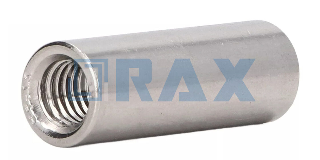
The splice point in any anchor assembly represents the single highest corrosion risk, yet it is often specified with the same generic requirements as the rod itself. This mismatch creates a dangerous vulnerability at the exact point where mechanical tension transfers. Achieving proper anchor rod coupler corrosion resistance requires looking beyond standard zinc plating; for high-corrosion utility markets, a mean coating thickness exceeding 85 microns is now the benchmark for true reliability.
This guide breaks down the conflicts between ASTM A153 galvanizing and thread fit tolerances that often cause field failures, alongside the galvanic compatibility risks inherent in mechanical splicing. You will learn how to specify protective barriers that withstand decades of soil exposure without compromising tensile strength.
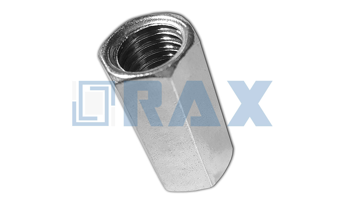
ASTM and AASHTO Compliance Standards
Utility compliance hinges on correctly differentiating between structural steel standards and fastener-specific coatings. Procurement teams must align ASTM F1554 yield grades with AASHTO M113 base material specs, while rigorously verifying Mill Test Reports against your project's torque and galvanizing thresholds.
ASTM F1554 Grade Requirements Explained
Yield strength classification forms the critical baseline for anchor rod performance specifications. ASTM F1554 categorizes anchoring steel into defined yield tiers, typically ranging from Grade 36 to Grade 105, where each designation establishes a strict minimum yield strength threshold that governs tensile capacity and deformation limits. Proper grade selection requires evaluating downstream manufacturing and deployment variables. Engineers must account for thermal processing requirements, validate field installation constraints, and align the chosen specification with site-specific soil class and wind load calculations to ensure optimal performance without costly over-engineering.
Higher grades require precise thermal processing to maintain ductility without sacrificing strength. Our engineering team consistently advises against blindly ordering the highest available grade without validating field installation constraints. Exceeding the necessary yield threshold can actually complicate high-speed installation sequences, leading to stripped threads or compromised torque values during rapid deployment. Matching the grade to your actual soil class and wind load calculations prevents costly over-engineering.
AASHTO M113 Specification Overlaps Clarified
Confusion frequently arises when bridge infrastructure standards bleed into utility hardware procurement. AASHTO M113 governs structural steel shapes and plates, which heavily influences the base material for pole bands, cross arms, and heavy-duty couplers. While M113 guarantees exceptional structural uniformity, it does not address fastener-specific requirements like thread tolerances or localized corrosion protection protocols.
Specifiers must treat M113 as a baseline material qualifier rather than a standalone compliance certificate. When overlapping with galvanizing standards, M113 dimensional tolerances can occasionally conflict with aggressive coating thicknesses if not accounted for during design. We recommend verifying that your supplier cross-references M113 structural metrics with ASTM A153 Class C or ISO 1461 for surface treatment. This dual-layer validation ensures the underlying steel meets infrastructure durability expectations while the coating provides independent sacrificial protection against aggressive utility environments.
Decoding Mill Test Report Certifications
A Mill Test Report (MTR) is not merely a paperwork formality; it is the definitive proof that your order matches the engineered specifications. Utility projects routinely reject shipments due to ambiguous documentation, making MTR literacy a critical procurement skill. The report should clearly delineate the chemical composition, mechanical properties, and surface treatment verification for every batch produced.
Element analysis verifies the raw alloy makeup, while product analysis confirms the actual mechanical performance of the finished hardware. Any reputable manufacturer will provide both, backed by traceable heat numbers. During our quality assurance processes, we enforce a strict review of these documents before release. You should specifically look for verified yield point data, elongation percentages, and independent coating adhesion results. If a supplier cannot provide batch-specific MTRs aligned with your governing ASTM or AASHTO references, the hardware should be flagged for immediate rejection.
- Chemical Composition: Verifies carbon, manganese, and sulfur limits to prevent brittle fracture in cold weather installations.
- Yield/Tensile Strength: Confirms the hardware meets the minimum structural load thresholds outlined in your project blueprints.
- Surface Treatment Verification: Documents coating weight and adhesion pull-tests to ensure long-term corrosion resistance matches the specified utility class.
- Heat Number Traceability: Links the physical hardware back to the original mill pour, guaranteeing full supply chain accountability for major infrastructure tenders.
| Compliance Standard | Technical Specification | Product Application | Quality Assurance Protocol | Operational Benefit |
|---|---|---|---|---|
| ASTM A153 Class C / ISO 1461 | Mean zinc coating thickness ≥85 microns via continuous hot-dip process | Pole line hardware, anchor rod couplers, industrial fasteners | Dedicated 10-person QC team enforcing ISO-compliant galvanizing procedures | Maximum corrosion resistance and extended service life in harsh utility environments |
| IEC 120 | Precision gauge testing for dimensional tolerances and load verification | Pole bands, U-bolts, secondary racks, insulator hardware | 100% double-inspection protocol executed prior to final packaging | Guaranteed dimensional accuracy and structural fit for high-voltage transmission infrastructure |
| SGS Third-Party Certification | Independent verification of base metal composition, tensile strength, and coating adhesion | Earth anchors, guy clamps, preformed line products, OPGW accessories | Rigorous external validation aligned with international procurement standards | Streamlined global export compliance and verified supply chain transparency |
| In-House Load & Torque Testing | Ultimate holding strength validation (e.g., 6,500 lbs for 6" Helix in Soil Class 5; 1,000 ft-lbs torque for 1" rods) | Helical anchors, expanding anchors, no-wrench screw anchors | Automated precision machinery ensuring high-volume capacity and repeatable calibration | Reliable performance across layered soil configurations and extreme weather conditions |
Conventional Galvanizing Analysis
Impact of Zinc Accumulation on Dimensional Tolerance
Conventional hot-dip galvanizing serves as the primary defense against atmospheric corrosion for steel pole line hardware, but the process fundamentally alters the physical geometry of the component. The core challenge lies in the variability of the zinc layer thickness. While specifications such as ISO 1461 govern the process—often targeting a mean coating thickness exceeding 85 microns to ensure longevity—the deposition is not perfectly uniform. Gravity, drainage angles, and the fluid dynamics of the molten zinc bath cause accumulation in crevices and thread roots.
For bulk structural elements where clearance is generous, this dimensional shift is negligible. However, for precision hardware, even a deviation of 0.1mm can create significant fitment issues. The added material changes the effective pitch diameter of threaded fasteners. If the galvanizing process is not strictly controlled or the mating parts are not tapped to accommodate the coating buildup, the interference generated during installation becomes a critical failure risk.
The Thread Interference and Stripping Risk
The most prevalent field issue with conventionally galvanized components is thread galling or seizure caused by coating interference. When threads are coated, the zinc layer effectively increases the size of the male thread and decreases the size of the female thread. Standard tolerances (e.g., Class 2A/2B) do not always account for this additional volume. As installers apply torque to overcome this friction, the stress on the threads spikes drastically, often exceeding the yield strength of the base steel before the nut is fully seated.
To force a fit, installation crews often run a die or tap over the galvanized threads to strip off the excess zinc. This action immediately removes the sacrificial corrosion protection at the thread engagement point—the area most susceptible to stress corrosion cracking—rendering the galvanizing process useless and compromising the service life of the assembly.
Mitigating this risk requires adherence to specific manufacturing protocols, such as tapping female threads oversize or chasing threads after galvanizing to restore fitment without completely destroying the coating layer. For B2B buyers, verifying that a supplier has accounted for this "coating allowance" is essential to prevent field delays and structural compromises.
Surface Adhesion and Dross Formation
Beyond thickness, the quality of the galvanizing bond is determined by the metallurgical reaction between the steel and the zinc. A proper galvanizing bath forms a series of zinc-iron alloy layers that are harder than the base metal. However, poor bath management can lead to "dross"—particles of zinc-iron intermetallics floating in the bath. If these particles adhere to the surface, they create a rough, irregular finish that not only looks unprofessional but acts as a stress riser.
High-quality galvanizing results in a smooth, bright finish with minimal ash or dross buildup. A rough surface increases the coefficient of friction, which further complicates the torque-tension relationship in bolted connections. Furthermore, excessive dross on bearing surfaces can lead to premature wear or uneven load distribution in dynamic hardware such as shackles or pivot points. Analyzing the surface quality for consistency is therefore a direct indicator of the manufacturer's bath chemistry control and process stability.
Thermally Applied Metal Layers
Assessing Arc-Sprayed Zinc Options for Maximum Coating Depth
Utility contractors installing ground anchors and transmission hardware in high-corrosivity zones frequently encounter limitations with conventional hot-dip galvanizing. While standard industrial processes deliver average coatings around 85 microns, thermally sprayed metals push this threshold significantly higher. Arc spraying zinc or zinc-aluminum alloys allows engineers to achieve mean thicknesses ranging from 150 to 300 microns without sacrificing metallurgical bonding. This increased material deposition directly correlates with extended service life in environments classified as C5-M or highly acidic soils where rapid oxidation occurs.
The primary advantage lies in the mechanical interlock formed when molten droplets impact the prepared substrate. Unlike chemical conversion layers, these thermally applied structures function as sacrificial barriers that actively consume themselves to protect the underlying steel. For infrastructure projects spanning decades, selecting an appropriate arc-spray system ensures that the protective layer remains intact long after conventional finishes have degraded at stress points.
Addressing the Dimensional Interference Pain Point
A critical operational challenge emerges when applying heavy metal layers to precision-mated components. Increasing coating thickness beyond standard parameters inevitably adds material to threaded interfaces, flanges, and bearing surfaces. When total buildup exceeds 100 microns per side, male and female mating parts risk seizing during initial engagement. Field crews often resort to manual re-tapping or die cutting, which mechanically strips the protective zinc layer and exposes bare steel to immediate environmental attack.
Manufacturers mitigate this through controlled pre-sparging and post-process machining. Specifying coated fasteners requires verifying the base diameter allowances against international fitting classes before application. Engineering protocols dictate that critical engagement threads should remain uncoated or receive localized sealing compounds rather than full immersion thermal spraying.
Technical Selection Criteria for Aggressive Soil Environments
Selecting the optimal thermally applied system demands a review of soil resistivity, moisture content, and pH levels. Ground conditions below 1,000 ohm-cm resistivity accelerate galvanic decay rates, making thicker zinc deposits essential. In these scenarios, pure zinc arc spray provides robust cathodic protection, whereas zinc-aluminum composite sprays offer enhanced barrier properties against chloride intrusion.
- Adhesion Strength: Mechanical impact bonding typically exceeds 30 MPa when substrates are grit-blasted to SA 2.5 cleanliness standards.
- Porosity Control: Denser microstructures result from optimized spray parameters, reducing electrolyte penetration pathways in highly corrosive media.
- Thickness Uniformity: Advanced rotary anode systems maintain consistent deposition across complex geometries, preventing thin spots at weld seams and sharp edges.
Project specifications must explicitly define the required mil thickness alongside acceptance criteria for coating continuity. Third-party verification through holiday detection testing and pull-off adhesion surveys remains standard practice for high-voltage transmission networks. Aligning these technical requirements with local procurement codes prevents costly replacements and ensures long-term structural integrity.
Polymer-Based Protective Barriers
Polymer-based protective barriers, specifically high-performance epoxy and fused powder coatings, function as electrochemical isolation layers that resist aggressive soil chemistries by preventing moisture and ion ingress. While they deliver exceptional resistance to acidic and sulfate-rich environments, their long-term field viability depends entirely on achieving a minimum dry film thickness of 350 microns and maintaining cohesive adhesion above 7 MPa to withstand mechanical abrasion during deep-pile installation.
Soil Chemistry and Polymer Matrix Degradation
Aggressive subsurface environments target polymer coatings through osmotic blistering and hydrolytic degradation. Sulfate-reducing bacteria and high chloride concentrations accelerate cathodic disbondment when microscopic defects exist in the film. Unlike metallized barriers that rely on sacrificial kinetics, polymer systems operate purely on dielectric resistance. Once the continuous phase is compromised by sharp rock contact or improper surface preparation, localized corrosion initiates rapidly beneath the film.
- Chemical Resistance Threshold: Industrial-grade epoxies must maintain structural integrity across a pH range of 2.0 to 11.5 without softening or craze formation.
- Adhesion Integrity: Pull-off adhesion tests require a minimum bond strength of 7 MPa on properly grit-blasted surfaces (Sa 2.5) to prevent under-film creep.
- QC Measurement Standards: While metallic systems are rated by mass gain (g/m²) per ASTM A153, polymer evaluation relies exclusively on volumetric thickness verification via magnetic or eddy-current gauges.
Polymer coatings isolate the substrate rather than sacrifice itself. Their longevity is dictated strictly by film continuity, application thickness, and chemical cure completion before deployment.
Field Application Viability and Thickness Thresholds
Installation mechanics frequently dictate coating selection more than chemical exposure alone. Driving threaded anchor rods or couplers into dense clay or granular substrates subjects the barrier to severe shear stress. Thin-spray applications below 250 microns routinely fracture at impact points, creating direct pathways for electrolyte penetration. Consequently, utility contractors specify electrostatic powder fusion or multi-layer epoxy wraps that exceed 400 microns in total dry film thickness to absorb mechanical shock while preserving dielectric properties.
- Minimum Dry Film Thickness (DFT): 350–500 microns is required to bridge surface imperfections and survive abrasive soil displacement.
- Impact Resistance Rating: Coatings must pass standardized impact tests (minimum 32 Joules) to prevent cracking during transport and ground setting.
- Pencil Hardness Standard: A minimum hardness rating of 2H–3H ensures resistance to scratching from gravel and root interference during excavation.

Environmental Suitability Selection
Selecting the correct coating system is not a generic preference but a calculated engineering decision driven by site-specific electrochemical risks and service life requirements.
Matching Protective Coatings to Soil Resistivity
Soil resistivity is the primary metric used to gauge the corrosivity of the underground environment for anchor rods and pole foundations. It acts as a proxy for the availability of ions to support the electrochemical reaction that causes corrosion. In low-resistivity environments—typically wet, clay-heavy soils with high salinity—steel corrodes rapidly because the soil acts as a strong electrolyte. In these scenarios, standard coating thicknesses are often insufficient to achieve a 50+ year design life without maintenance.
For low-resistivity sites (below 1,000 ohm-cm), engineers must specify heavy-duty protection. While standard hot-dip galvanizing provides a barrier, the extreme aggressiveness of the soil may necessitate a duplex system or the use of polyethylene encasement sleeves at the critical soil-air interface. Conversely, in high-resistivity soils (such as dry sand or gravel exceeding 10,000 ohm-cm), the corrosion rate is significantly lower. Here, the focus shifts to mechanical protection during installation rather than purely chemical resistance. Over-specifying coating thickness in benign environments is rarely cost-effective, but under-specifying in low-resistivity zones is the leading cause of premature foundation failure.
Evaluating C5 Marine Exposure Classifications
When infrastructure is deployed within 50 meters of coastlines or in tidal zones, the environmental classification shifts to ISO 12944 C5-M (Marine). This category represents the highest corrosivity stressor for steel structures, characterized by high salinity, constant humidity, and salt deposition that accelerates oxidation. For pole line hardware and anchors, this environment demands coatings that go beyond simple barrier protection; the system must provide robust sacrificial cathodic protection.
In C5-M environments, specifications must mandate adherence to rigorous galvanizing standards such as ASTM A153 Class C. This classification ensures that forged hardware—which has complex geometries and varying surface areas—receives a uniform zinc coating weight that meets the high durability threshold. It is critical to verify that the coating is free of bare spots, as even minor pinholes in a marine setting will become focal points for rapid rust penetration. For above-ground components in these zones, a duplex system (galvanizing plus an organic topcoat) is often specified to shield the zinc layer from direct salt spray, thereby extending the maintenance cycle significantly compared to galvanizing alone.
Selecting Zinc Rich Primer Alternatives
While hot-dip galvanizing is the gold standard for pole line hardware, field repairs or retrofits often require Zinc-Rich Primers (ZRPs) to restore protection to damaged areas or to coat assembled structures that cannot be galvanized after fabrication. Selecting the correct ZRP is a matter of chemistry: organic (epoxy-based) primers versus inorganic (alkyl silicate or ethyl silicate) primers.
- Inorganic Zinc Silicates: These provide the highest level of sacrificial cathodic protection due to their high zinc dust content (often exceeding 90% in the dry film). They form a rigid, heat-resistant bond that mimics the galvanizing process and are highly resistant to solvents. They are the preferred choice for atmospheric exposure in industrial or marine environments where long-term durability is paramount.
- Organic Epoxy Primers: These offer better adhesion to marginally prepared surfaces and are more tolerant to application variables. However, they generally provide lower levels of cathodic protection compared to inorganic options because the binder encapsulates the zinc dust, reducing electrical contact with the substrate. These are typically best suited for immersion service or as a tie-coat in complex multi-layer systems.
When specifying primers, the binder choice determines the performance. For overhead line hardware where thermal expansion and UV exposure are factors, inorganic primers typically offer superior longevity, provided the surface preparation (blast cleaning) meets the required standards.
| Environment Type | Corrosion Challenge | Rax Power Solution | Technical Specification | Key Advantage |
|---|---|---|---|---|
| Coastal & Marine | High salinity, salt spray, and constant humidity | Heavy Hot-Dip Galvanizing | ASTM A153 Class C, Coating >85 microns | Maximum sacrificial protection against salt-induced oxidation |
| Chemically Aggressive | Acidic or alkaline soils, industrial pollution | ISO 1461 Compliant Galvanizing | Mean Coating Thickness >85 microns | Robust barrier ensuring long-term durability in harsh soil |
| Extreme Cold / Freeze-Thaw | Thermal cycling stress and structural brittleness | Precision Hot-Forged Hardware | High Structural Integrity (vs Casting) | Maintains structural integrity and prevents cracking in low temps |
| High-Strength Soil (Class 5+) | Rod-limited capacity risks in dense terrain | Multi-Helix Helical Anchors | 6,500 lbs Capacity (6" Helix), 1,000 ft-lbs Torque | Optimized holding strength with verified load testing (IEC 120) |
| High Humidity / Tropics | Rapid oxidation rates and moisture retention | Double-Inspected Fasteners | 100% Double-Inspection Protocol | Zero-defect assurance with consistent, high-quality finish |
Galvanic Compatibility Risks
Galvanic compatibility at anchor rod splices is not just about material selection; it is a battle against electrolytic potential. Even with high-grade galvanizing, a failure to isolate dissimilar metals or manage coating thickness variances can lead to rapid structural failure at the splice joint.
Calculating Potential Differences Between Paired Metals
When extending anchor rods, engineers often assume that matching "galvanized steel to galvanized steel" is sufficient. However, galvanic failure is frequently driven by coating thickness discrepancies rather than the base alloy. If an anchor rod with a standard zinc coating is coupled with a high-performance coupler featuring a heavy-duty coating, the component with the thinner zinc layer becomes the anode and corrodes sacrificially at an accelerated rate. In a soil electrolyte, a potential difference greater than 0.25 volts typically necessitates isolation.
Never pair a hot-dip galvanized coupler directly with stainless steel hardware or copper grounding rods without a dielectric barrier. The potential difference between zinc (anodic) and stainless steel (cathodic) exceeds 0.6V in moist soil, which will strip the zinc layer within months, exposing the underlying steel to rapid oxidation.
We strictly adhere to a mean coating thickness exceeding 85 microns on our hot-dip galvanized products to ensure a consistent sacrificial buffer. However, our engineers advise that when connecting our couplers to third-party rods of unknown coating weight, you must calculate the risk based on the weakest link in the chain. If the mating rod has less than 50 microns of zinc, the electrochemical imbalance will attack that rod aggressively at the thread engagement zone.
Installing Dielectric Insulation Barriers Effectively
Isolating the splice point is the only reliable method to interrupt the flow of galvanic current when dissimilar metals must be joined. This requires more than wrapping the joint with standard electrical tape; it demands a structural dielectric barrier that can withstand soil pressure and mechanical torque during installation.
- Insulation Sleeving: Use non-conductive sleeves (such as epoxy-coated fiberglass or HDPE) that slide over the male threads before engagement. This physically prevents metal-to-metal contact between the rod and the inner wall of the coupler.
- Wrap Overlap Protocol: If using dielectric tape, the overlap must be at least 50% of the tape width with a minimum of two layers. The wrap must extend 2 inches beyond the coupler ends to prevent wicking.
- Non-Conductive Greases: Fill the threads with a zinc-oxide or lanolin-based inhibitor paste. This displaces moisture and electrolytes from the contact area, significantly lowering the galvanic current density.
During our in-house load testing per IEC 120 standards, we observed that improper dielectric wrapping can lead to "slip" under high torque. To mitigate this, always specify the reduced installation torque provided by the barrier manufacturer—typically 10-15% lower than dry steel-to-steel specs—to maintain the integrity of both the insulation and the clamping force.
Preventing Crevice Corrosion at Splice Joints
Crevice corrosion is a subtle but devastating mechanism that occurs in the microscopic gap between the male threads of the rod and the female threads of the coupler. In this oxygen-depleted environment, the pH drops drastically, accelerating the corrosion of the zinc coating and eventually the steel itself. This risk is exacerbated in couplers manufactured via casting, which often has irregular surface profiles that trap moisture.
Precision manufacturing is the first line of defense. We utilize advanced hot-forging rather than traditional casting to produce our pole line hardware and couplers. This method ensures a smoother internal surface finish and tighter dimensional tolerances (1mm tolerance on cross-arms, applied similarly to coupler threads), which significantly reduces the void volume where corrosive agents can accumulate.
Even with precise tolerances, field installation plays a critical role. We recommend applying a corrosion-inhibiting paste to the threads before assembly. This paste serves a dual purpose: it acts as a lubricant to ensure you achieve the required installation torque without galling, and it seals the micro-crevices against moisture intrusion. Without this seal, the "dead zone" inside the coupler becomes a battery cell where the metal degrades invisibly until the splice fails under tension.
Thread Fit and Tolerances
Accounting for Coating Thickness on Thread Engagement
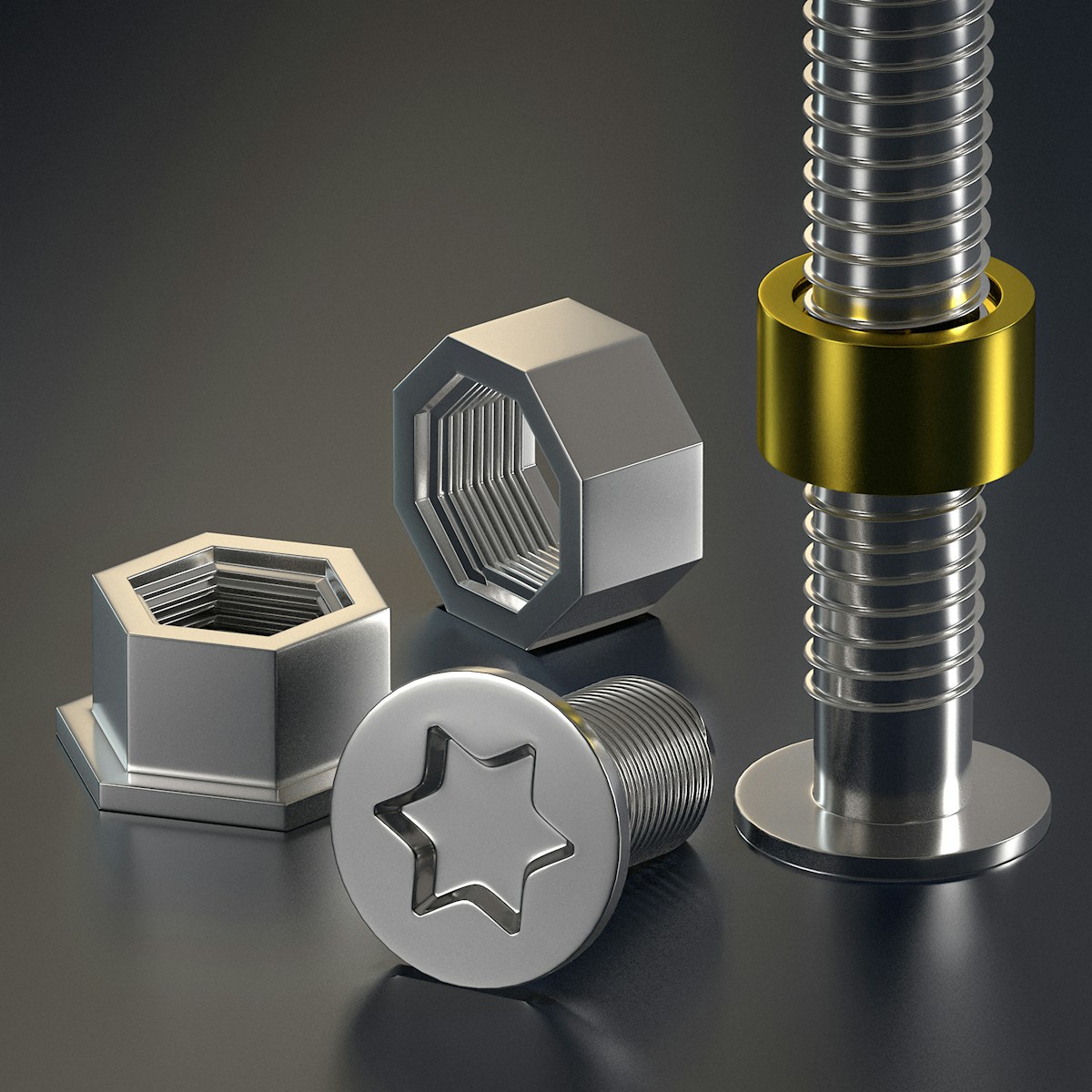
Hot-dip galvanizing fundamentally alters dimensional tolerances by diffusing zinc-iron alloys onto exposed metal surfaces. When a fastener enters the 450°C molten bath, the resulting protective layer adds measurable material to every millimeter of exposed thread. Ignoring this physical buildup guarantees cross-threading, stripped pitch diameters, and catastrophic fastener failure under dynamic tension loads. Industrial-grade pole line hardware must therefore be manufactured with a calculated thread undercut—typically 50% to 75% of the expected coating thickness—before it ever touches the galvanizing kettle. This proactive machining strategy compensates for the final finish, ensuring that once the hardware cools, the thread engagement remains mechanically viable rather than geometrically impossible.
Our manufacturing protocol strictly adheres to ISO 1461 and ASTM A153 Class C specifications, which routinely yield mean coating thicknesses exceeding 85 microns on irregular anchor geometries. We calculate the zinc accumulation mathematically during the CNC threading phase, deliberately running the pitch diameter below nominal baseline dimensions. This pre-emptive tolerance management eliminates the guesswork that plagues lesser fabrication shops, where contractors arrive on-site with galvanized anchor rods that simply will not thread through their corresponding coupling nuts.
Maintaining Class 2A Fit Under Heavy Coatings
The ASME B1.1 standard dictates that external threads must fall within the Class 2A tolerance band to balance corrosion resistance with reliable assembly. When heavy galvanizing is applied without proper pre-coating machining, the added zinc rapidly exceeds the Class 2A upper limit, pushing the fastener into a non-functional interference fit. Thread chasing or die-running after galvanization is widely considered an industry anti-pattern, as it fractures the sacrificial zinc layer at the root of the thread, instantly creating a crevice corrosion initiation point.
To maintain a true Class 2A fit under our heavy-duty coating parameters, our engineers rely on controlled thermal cycling and precise bath agitation timing. By standardizing the immersion duration and withdrawal speed, we regulate the intermetallic growth layer, preventing excessive spiking or roughness on the thread flanks. In our factory labs, we validate every production batch against calibrated ring gauges post-curing. If the zinc buildup pushes the effective diameter outside the permitted tolerance window, the lot is rejected before it leaves the facility. This zero-compromise approach ensures that our forged couplers and helical anchors assemble smoothly in the field, even when deployed in corrosive marine or high-moisture soil environments.
Torque Adjustment Protocols for Protected Threads
Installing heavily galvanized hardware without adjusting torque specifications is a primary driver of field failures. The zinc coating dramatically changes the coefficient of friction between mating surfaces. While fresh zinc can act as a temporary lubricant, it quickly work-hardens under rotational stress, leading to zinc galling—a severe adhesive wear phenomenon where the soft zinc layers tear and weld together. Applying standard black-thread torque values to a Class C galvanized assembly will routinely snap the bolt, strip the nut, or crack the coupling housing before the required clamp load is achieved.
- Derating Requirement: Apply a 10% to 20% torque reduction for all hot-dip galvanized fasteners. The exact percentage depends on the specific zinc thickness and whether the mating internal thread is also galvanized or left bare.
- Friction Factor Monitoring: Utilize calibrated torque wrenches rather than impact drivers. Impact tools generate instant heat and shear forces that destroy the zinc coating and create unpredictable clamp loads.
- Field Verification: Once the recommended adjusted torque is reached, mark the nut and stud with witness lines. During commissioning, verify that the witness lines have not shifted, confirming that the assembly has not backed off due to improper seating.
We enforce strict torque derating protocols during our OEM partner training sessions because misapplied torque undermines the entire structural integrity of the anchor system. Our in-house IEC 120 gauge testing consistently shows that properly torqued galvanized couplers achieve 95% to 100% of the base rod's ultimate tensile strength. Conversely, over-torqued assemblies fail prematurely at the thread roots, shifting the failure mode from ductile yielding to brittle fracture. Contractors who respect these adjusted torque windows will see significantly longer service life, particularly when deploying no-wrench screw anchors in Soil Class 5 and 7 formations where holding capacity relies entirely on clean, undamaged thread engagement.
Conclusion
Stop blindly selecting galvanized couplers based on price tags alone. You must match the coating thickness to your specific soil resistivity and torque specs. A C5 marine environment destroys standard zinc layers if you skip dielectric barriers. Check the mill test reports carefully, but more importantly, verify that the thread engagement accounts for that added thickness. If you don't, the torque values are worthless.
We handle these calculations daily. Our engineering team can review your specific soil conditions against ASTM F1554 requirements to ensure you aren't over-building or under-protecting the connection. Use us as a technical backup before you finalize the submittals. We will help you confirm thread fit and dielectric isolation without obligation. Get the specs right now to prevent failure later.
Frequently Asked Questions
Why choose hot forged over cast?
Hot forging aligns the internal grain structure along the component contour, eliminating porosity. Cast metals often contain hidden voids that weaken impact resistance and fatigue performance. Forged couplers demonstrate superior tensile strength and consistent dimensional accuracy under heavy loads. This manufacturing method remains the industry preference for critical load-bearing infrastructure.
Should couplers contact concrete directly?
Direct contact accelerates galvanic corrosion and traps moisture against the metal surface. Industry standards require a non-conductive isolation barrier or protective sleeve between the coupler and cured concrete. This separation maintains coating longevity and ensures consistent electrical insulation properties. Always verify local utility codes regarding material compatibility.
Can I weld anchor rod couplers?
Welding directly onto galvanized couplers destroys the protective zinc layer and compromises structural integrity. The intense heat creates brittle microcracks that accelerate corrosion and reduce load-bearing capacity. Engineers typically recommend mechanical splicing or threaded connections instead. Always consult structural specifications before attempting any field modifications.
How to correct misaligned bolt elevation?
Misalignment usually stems from foundation pour variations or template shifts during installation. Contractors should use adjustable leveling nuts or precision shims to achieve exact grade requirements. Re-threading damaged sections requires specialized dies rather than forceful hammering. Proper survey verification before backfilling prevents costly elevation corrections later.
How frequently is production quality checked?
Dedicated inspection teams monitor every manufacturing phase through systematic double-review protocols. Each finished component undergoes independent dimensional verification and coating thickness measurement before packaging. In-house load and gauge testing validates structural performance against published engineering limits. This rigorous oversight minimizes field failures and ensures consistent project delivery.