
Downtown poles rarely get the luxury of space. A service alley in an older district puts a wooden pole within arm’s reach of brick walls, fire escapes and dumpster rows. Hang a conventional crossarm there and the outer conductor ends up pointed at masonry the code says it must avoid. An alley arm solves the problem by shifting the conductor path to one side of the pole. The sections below explain when the side mount wins, how the clearance math works, and which hardware makes the assembly hold its line.
This guide takes the manufacturer’s view of the problem. RaxPower has built pole line hardware since 2003, and its 170+ person team hot-forges fittings like these every day. The aim is practical: help utility specifiers, line contractors and distributors choose, mount and pair a side arm with confidence.
What an Alley Arm Does on the Pole
An alley arm is a crossarm mounted to one side of the pole instead of across the top. Crews also call it a side arm, and utility construction standards treat the layout as routine. Cowlitz PUD publishes Drawing 3-130 covering single and double side-arm setups, and SDG&E’s overhead standards include a dedicated steel-pole version. The arm projects at a right angle to the line direction, so conductors sit beside the pole face rather than over both shoulders. Because the load hangs off-center, the whole assembly depends on rigid bracing to stay aligned.
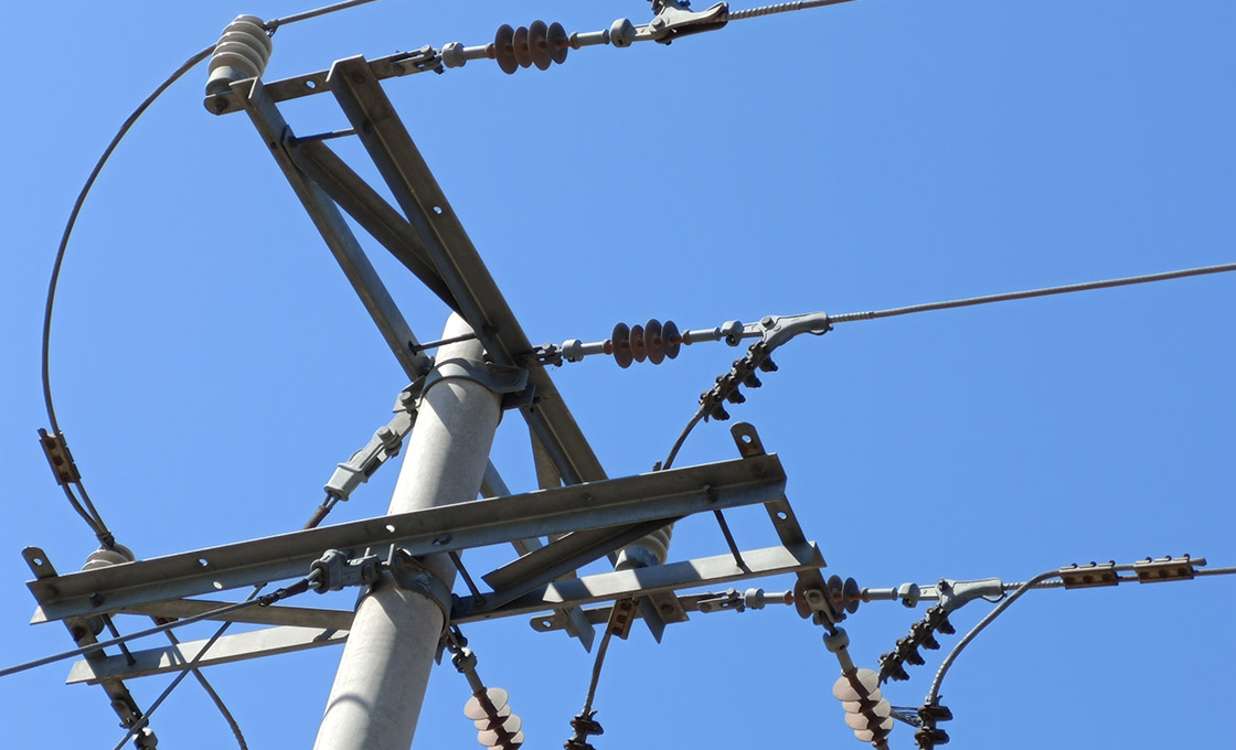
That bracing requirement is not cosmetic. MacLean Power’s catalog notes that one-sided arms require rigid bracing to keep distribution and transmission lines in proper alignment. In practice that means an angle-steel brace set at 45 degrees, a machine bolt at the arm, and lag screws at the pole. A dedicated alley arm brace ships with a welded lineman step for exactly this kind of work. Get the brace right and the arm behaves like any other crossarm; get it wrong and the offset load slowly walks the conductors out of position.
Urban Clearances That Force the Side Mount
Picture the service alley behind a downtown block: brick walls, fire escapes, dumpster rows, and one wooden pole hugging the property line. In that corridor the enemy is not load or span length. It is the wall.
The National Electrical Safety Code sets the floor. NESC Table 234-1 calls for 7.5 feet of horizontal clearance to walls, projections and guarded windows. That figure covers supply cables above 750 volts through 22 kV phase-to-ground, dropping to 5.0 feet at 0 to 750 volts. Many alley lines predate these rules, which is why utilities inherit violations when they rebuild downtown circuits. The code, revised every five years and published by IEEE, has made clearance rules more explicit with each cycle.
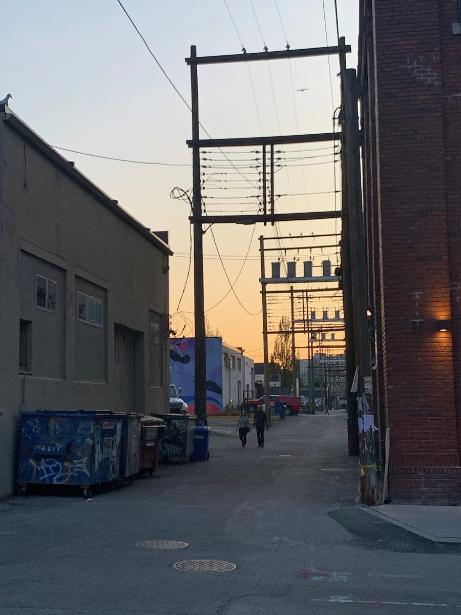
This is the environment where a standard two-sided crossarm becomes a liability. One of its ends always points at somebody’s building. A side-mounted arm points both its insulators and its conductors toward the free half of the right-of-way instead.
How the Offset Math Works in a Narrow Alley
A 14-foot alley with tall buildings on both sides shows the arithmetic. Two walls at 7.5 feet each consume 15 feet, and a T&D World analysis of alley rebuilds found exactly this bind: the space is gone before a single conductor arrives. Undergrounding rarely rescues the project; one clearance analysis put the cost at millions of dollars for just a few city blocks.
The side arm attacks the problem geometrically. The arm works like a truck mirror: the pole stays put while the carrying surface folds toward the space that is actually free. Sliding the conductor path toward the alley centerline recovers inches on each side. Length options of 5, 7 or 10 feet let the crew tune the offset to the measured wall distance.
Covered conductor closes the remaining gap. Footnote 2 of Table 234-1 allows the wall clearance to drop by 2 feet where conductors, splices and taps carry covering strong enough to limit short-circuit likelihood from momentary contact. Combined with a side arm, that reduction is often what lets a primary circuit fit an alley that open wire cannot legally serve.
Anatomy of a Street-Ready Alley Arm Setup
Catalogs keep the geometry consistent, which makes specifying straightforward. MacLean’s 5- and 7-foot side-arm braces use 1-3/4 by 1-3/4 by 3/16 inch angle steel. The 10-foot class steps up to 2 by 2 by 1/4 inch section on the side arm datasheet. Mounting holes run 9/16 or 11/16 inch to match standard pins and fasteners.
The parts around the arm matter just as much as the arm itself:
- Angle brace set, mounted at 45 degrees, with a machine bolt at the arm.
- Two 1/2-inch lag screws pulling the brace to the wood pole.
- Crossarm pins and insulators sized to the conductor class.
- A welded lineman step on the brace for safe access in tight alleys.
Because the arm shares its hole patterns with standard cross arm assemblies, insulator and pin selection carries over from the rest of the line. That consistency is worth demanding when you quote the assembly.
Mounting an Alley Arm on Downtown Wood Poles
When the bucket truck swings into a 14-foot easement, setup time is the currency. Downtown work adds traffic control, pedestrian barriers and limited lay-down space, so the field sequence should be settled before the truck door opens. Wood poles actually make the job easier. Lag-screw retention works well in sound timber, and crews can inspect for rot or shell damage while the arm position is marked.
Field sequence
- Confirm the target conductor position, then measure the required offset from the pole face.
- Hold the arm square to the pole at a right angle and mark the hole positions.
- Drill pilot holes, then fasten the brace to the arm with the machine bolt.
- Drive the two 1/2-inch lag screws into the pole and seat the 45-degree brace.
- Hang insulators and pins, dress the conductors, and run a final torque and alignment check.
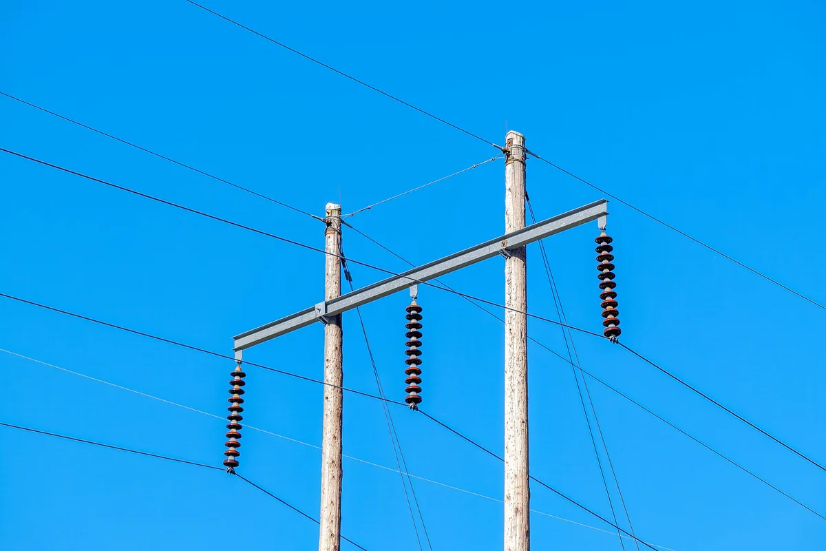
Two details separate a clean install from a callback. First, verify pole condition before lag loading it; a decayed shell will not hold threads. Second, use the welded lineman step rather than improvised footings, because alley work happens over dumpsters, fences and doorway traffic where three points of contact are hard to keep.
Hardware That Pairs With a Side-Mounted Arm
A side-mounted arm never works alone, and the supporting cast is mostly stock material. Flat and angle braces carry the offset load back to the pole. U-bolts clamp the arm where it meets steel banding. Crossarm pins and insulator pins take the conductor, while dead-end grips handle the tight terminations alleys force on rebuilds.
Two pairing rules keep the assembly honest. Match hardware galvanizing so a fresh fitting does not sacrifice itself protecting an old one. And where the line needs a double-arming plate for extra bolt bearing, add it deliberately rather than by habit, because the plate changes the hole-loading pattern on the pole.
Most of these parts are everyday pole line hardware items, so distributors can stock the whole side-mount assembly as one kit under a single part number.
Specifying Side Arms for Your Next Downtown Job
A side-mount specification fails in the details, not the concept. Nail these six lines down before the purchase order goes out:
| Spec line | What to confirm |
|---|---|
| Arm length | Match the measured wall offset; 5, 7 and 10 ft are standard, custom cuts available |
| Angle section | 1-3/4 in class to 7 ft; step up to 2 x 2 x 1/4 in at 10 ft |
| Hole pattern | 9/16 or 11/16 in mounting holes, matched to pins and braces |
| Coating | Hot-dip galvanized to ASTM A123 / ISO 1461 |
| Bracing | 45-degree brace set with machine bolt plus two lag screws |
| Access | Welded lineman step; custom drill patterns for special framing |
Side-Mounted Cross Arms, Built to Your Drill Pattern
Hot-forged cross arms and side-arm braces in galvanized carbon steel, supplied to utility, contractor and distributor programs worldwide with inspection documentation available.

Material and Galvanizing Choices for Street Duty
The default build for street-level work is carbon steel angle with hot-dip galvanizing. Forged carbon steel carries the offset load without the weight penalty of heavier sections, and it takes a zinc coating uniformly, inside corners included. That coating is the whole defense system in an alley, where de-icing salt splashes upward and vehicle exhaust accelerates corrosion at breathing height.
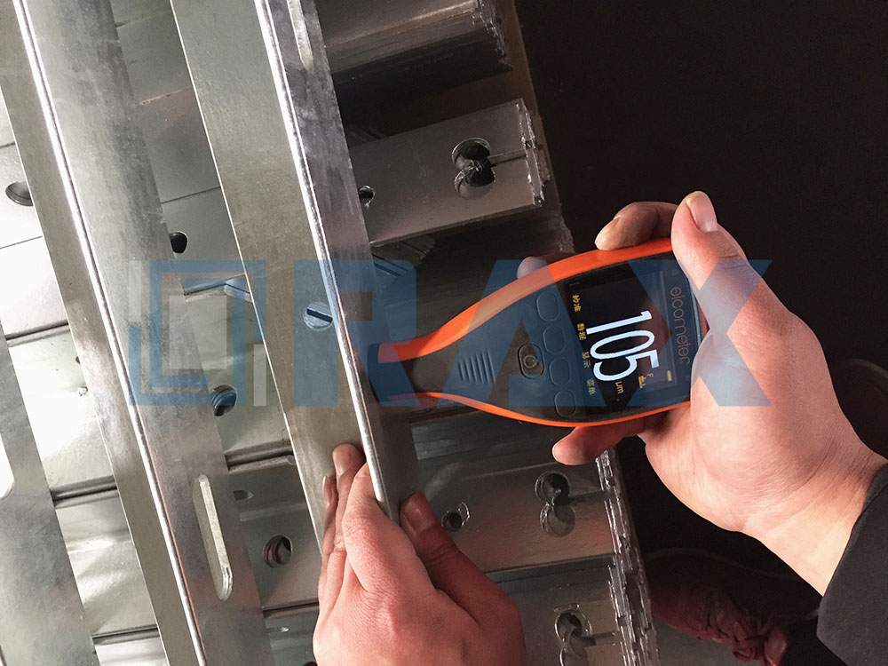
Specify the coating, not just the material. Hot-dip galvanizing to ASTM A123 or ISO 1461 with mean thickness above 85 microns gives the zinc sacrificial depth to outlast thin electroplate many times over. On incoming inspection, a magnetic gauge reading at the arm’s lower face tells you more about street life expectancy than any certificate number.
Field Checklist for a Downtown Alley Installation
Before the crew leaves the yard, run this list against the work order:
- Clearance survey signed off, with wall projections measured, not estimated.
- Pole condition confirmed sound enough for lag-screw retention.
- Arm length matched to the measured offset, not to whatever is on the truck.
- Brace hardware galvanizing matched to the arm and pole banding.
- Final conductor position photographed for the record.
In our experience, the brace is the part crews under-specify most often. The arm gets the attention because it carries the insulators, but alignment over a five-year alley cycle is decided by the 45-degree brace and its two lag screws. Buy them as a matched set.
Key Takeaways for Urban Pole Lines
A side-mounted arm wins where walls eat the right-of-way. Match arm length to the measured offset, brace it at 45 degrees, and insist on hot-dip galvanizing that survives street-level corrosion. RaxPower builds cross arms and side-mount assemblies to custom drill patterns for utility and contractor programs worldwide.
Frequently Asked Questions
What does an alley arm do on a utility pole?
It carries conductors on one side of the pole, at a right angle to the line, so wires can pass buildings in alleys and tight easements. Braces set near 45 degrees keep the one-sided load aligned.
How far must conductors sit from a building wall?
NESC Table 234-1 sets 7.5 feet of horizontal clearance for supply cables above 750 volts through 22 kV, and 5.0 feet at 0 to 750 volts. Confirm the edition your commission adopts.
Can you mount an alley arm on a wood pole downtown?
Yes. The standard method bolts the brace to the arm with a machine bolt, then pulls it to the pole with two 1/2-inch lag screws. Mark and drill pilot holes square to the pole first.
What hardware belongs in a side arm assembly?
Angle or flat braces, a machine bolt at the arm, lag screws at the pole, crossarm pins, insulators, and U-bolts where steel banding is used. Alley dead ends add dead-end grips.
What material should a side arm be made from?
Hot-dip galvanized carbon steel angle is the industry default for street duty. Coatings to ASTM A123 or ISO 1461 with mean thickness above 85 microns resist salt splash and exhaust-driven corrosion.
What lengths do side arms come in?
Catalog lengths of 5, 7 and 10 feet cover most offsets, with 9/16 or 11/16 inch mounting holes. Manufacturers can cut custom lengths and drill patterns to match your pole framing.
Quick Definition
An alley arm is a side-mounted crossarm assembly that carries overhead conductors beside a utility pole instead of across the top. Braced at roughly 45 degrees, it shifts the conductor path away from building walls in alleys and narrow urban rights-of-way where standard crossarms cannot meet required clearances.
Key Data
- NESC Table 234-1 requires 7.5 ft of horizontal clearance from supply cables above 750 V through 22 kV to building walls, and 5.0 ft at 0-750 V.
- A 14 ft alley needs 15 ft of wall clearance before conductors arrive; a side-mounted arm plus covered conductor (2 ft footnote reduction) closes the gap.
- Standard braces mount at 45 degrees with a machine bolt at the arm and two 1/2-inch lag screws at the pole.
- Catalog arm lengths run 5, 7 and 10 ft; hot-dip galvanizing to ASTM A123/ISO 1461 with mean coating above 85 microns.
Concise Answers
Is an alley arm the same as a side arm? Yes, “side arm” is the formal category name for the same side-mounted assembly; the alley nickname stuck from duty in tight passages.
Which poles take side arms? Wood poles take the lag-screw brace method directly; standards also cover steel-pole versions.
Does the arm replace a full crossarm? No, it complements the line wherever one side of the right-of-way is blocked by buildings.