

Most procurement directors focus on tensile ratings and corrosion warranties when specifying an armor rod, but the field installation technique determines whether that hardware actually holds up under aeolian vibration. The component wraps around the conductor at every suspension or tension clamp, distributing the concentrated bending stress that would otherwise fatigue individual strands. The trick is fanning the helical rods correctly during application. Get the pitch wrong, leave a gap at the center mark, or force a twist past the recommended limit, and you have created a failure point that no spec sheet can fix.
Application guidelines show that on conductors 4/0d and larger, crews should never subset more than four rods at a time during the initial fan-out, and every rod end must land within two inches of its neighbor after the final snap. The next sections break down the tool prep, conductor verification steps, live-line safety protocols, and the exact fan-and-seat sequence that keeps that rule achievable in the air. You will walk away with a repeatable installation rhythm that protects your project safety record and eliminates the hidden corrosion costs caused by damaged strands beneath the grip zone.
Tools and Equipment You’ll Need for Fanning
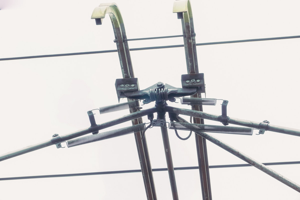
Effective fanning requires a precision-focused toolset: insulated rotatable heads for control, dielectric cleaning agents for surface prep, and calibrated gauges to eliminate sizing errors.
Insulated Hot Stick Heads for Rod Manipulation
Standard universal hot stick heads are often insufficient for the delicate helical application required during armor rod installation. To effectively fan the rods without damaging the conductor or dropping the hardware, crews must utilize hot sticks equipped with specialized rotatable heads and snap-lock mechanisms. These attachments allow the lineman to maintain constant rotational control of the rod end loop while keeping a safe distance from the energized conductor.
The mechanical interface between the stick head and the rod must be rigid. A loose connection leads to “wobble,” which can misalign the helix pitch and compromise the rod’s grip. Our engineering team emphasizes that the lever action of a quality stick head must translate directly into torque without slippage, ensuring the preformed rods seat evenly against the conductor strands.
- Rotatable Head Mechanism: Allows for 360-degree manipulation of the rod to maintain consistent tension during the fanning process.
- Snap-Lock Jaw: Ensures a secure hold on the rod’s eye or grip tag, preventing accidental drops which are costly and dangerous on live lines.
- Dielectric Rating: Tools must meet or exceed IEEE 516 standards for the specific line voltage to ensure crew safety.
Non-Conductive Cleaning Wipes and Solvents
Surface contamination is a primary enemy of conductor protection. Before fanning begins, the conductor surface must be free of oxidation, grease, and industrial residue that could prevent the armor rods from achieving proper contact. However, using standard shop rags or aggressive chemical solvents on energized lines creates significant safety and compatibility risks.
Crews should strictly use non-conductive, lint-free wipes pre-saturated with isopropyl alcohol (IPA) or specialized electrical cleaners. These solutions evaporate quickly, leaving no residue that could attract dirt or interfere with the galvanic compatibility between the armor rod and the conductor. In our manufacturing tests, we have found that even a microscopic layer of oil can reduce the frictional grip of helical products by up to 15%, potentially leading to slippage under load.
- Lint-Free Composition: Prevents fibrous debris from getting trapped in the rod helix, which could otherwise cause localized overheating or arcing.
- Fast Evaporation: Minimizes downtime between cleaning and installation, crucial for maintaining workflow efficiency during line outages.
- Material Compatibility: Solvents must be safe for both aluminum conductors (ACSR) and the zinc-aluminum coating of the rods to prevent corrosion.
Calibrated Conductor Diameter Gauges
Sizing confusion is a leading cause of installation failure. Misidentifying a conductor diameter results in armor rods that are either too loose (providing no damping) or too tight (damaging outer strands). To mitigate this, field technicians must carry calibrated conductor diameter gauges rather than relying on visual estimation or outdated stringing charts.
Precision is non-negotiable. Since we utilize automated machinery to maintain a strict 1mm tolerance on our forming mandrels, the field measurement must match this precision. A high-quality Vernier caliper or a dedicated “go/no-go” conductor gauge provides the immediate certainty needed to select the correct rod catalog number. This verification step is the only reliable defense against the costly downtime associated with mismatched hardware.
- Vernier Calipers (Digital/Dial): Essential for measuring the overall diameter of multi-layer conductors like ACSR to account for stranding compression.
- ISO/IEC Compliance: Gauges should be calibrated periodically to ensure measurement accuracy aligns with the manufacturing tolerances of the hardware being installed.
- Stranded vs. Solid Adjustment: The gauge must account for the “lay” of the strands to avoid false low readings on rough conductor surfaces.
Check the Conductor and Armor Rod Before Starting
Pre-installation validation is the critical control point preventing mechanical mismatch. Ensuring conductor diameter alignment and surface integrity is mandatory to mitigate fatigue failure from aeolian vibration.
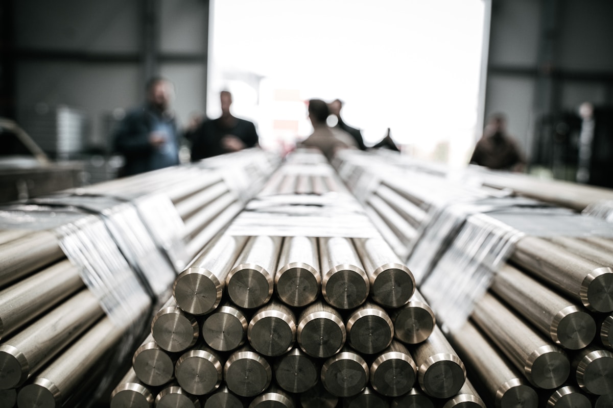
Before any installation commences, the integrity of both the conductor and the armor rods must be verified. This stage is not merely administrative; it is the primary defense against long-term fatigue failures and immediate mechanical slips. Failure to detect dimensional variances or surface defects at this stage compromises the entire damping system, leading to premature line aging and costly maintenance interventions.
Verifying Conductor Diameter Compatibility
Accurate sizing is the cornerstone of effective armor rod application. While catalog data provides nominal dimensions, actual conductor diameters can vary due to manufacturing tolerances or thermal contraction. Relying solely on color codes or generic labeling without physical verification is a common source of field error.
Technicians must use calibrated gauges to measure the conductor at multiple points along the installation span. This ensures the selected armor rod provides the optimal grip pressure. If the rod is sized for a diameter larger than the actual conductor, the helical formation will not seat correctly, resulting in a loose fit that fails to dampen vibration. Conversely, an undersized rod can over-compress the strands, potentially damaging the inner layers and creating stress concentrations that accelerate fatigue.
- Tolerance Verification: Confirm that the measured conductor diameter falls strictly within the acceptance range specified for the rod’s catalog number.
- Multi-Point Measurement: Measure the conductor at three separate locations to account for any ovality or inconsistent lay length along the strand.
Inspecting Rods for Transport Deformation
Armor rods are engineered preformed components designed to maintain a specific helical shape that distributes mechanical stress evenly. However, the logistics of transport and handling can compromise this geometry. Rods that have been crushed, dropped, or improperly stacked may exhibit flattening, stretching, or kinking that renders them unsuitable for use.
A deformed rod loses its ability to maintain uniform contact with the conductor. When the engineered helical shape is altered, the load distribution becomes uneven, concentrating pressure on specific points of the conductor rather than dispersing it. This negates the protective benefit of the rod and can actually induce damage. Inspectors must look for loss of preformation tension—where the rods no longer snap back to their original shape—and ensure that the individual strands of the rod bundle are not splayed or flattened.
Identifying Surface Abrasions on Conductor Strands
The conductor surface acts as the interface for all mechanical stress transfer. Even before installation, conductors may sustain abrasions from handling equipment, running over rollers, or contact with structures during stringing. Installing armor rods over damaged conductor strands without assessment is a critical error, as the rod will conceal the defect while the vibration continues to exploit it.
Surface abrasions, nicks, or “bird-caging” (unraveling of strands) act as stress risers. These are the primary initiation points for fatigue breaks under the cyclic loading caused by aeolian vibration. If damage is detected, the conductor must be repaired or replaced before the armor rod is applied. The armor rod is designed to protect against future wear and distribute existing load, but it cannot repair a broken strand or fill a deep nick. In high-vibration scenarios, an unrepaired abrasion covered by a rod will likely propagate into a catastrophic failure.
- Stress Riser Detection: Look for localized smooth spots or flattened areas on the outer strands, which indicate friction burn or mechanical impact.
- Coating Integrity: Ensure the conductor’s grease or coating (if applicable) is intact, as corrosion buildup under the rod can cause uneven expansion and conductor necking.
| Pre-Start Inspection Item | Engineering Acceptance Standard | Failure / Defect Indicators | Immediate Corrective Action |
|---|---|---|---|
| Conductor Diameter & Surface Condition | Nominal conductor diameter must match the selected armor rod size chart; surface must be smooth and free of nicks, abrasions, or bird-caging. | Mismatched gauge causing loose fit; visible strand damage concentrating mechanical stress. | Stop installation; select correct armor rod per sizing chart or repair conductor with approved splice sleeve. |
| Galvanizing & Coating Integrity | Hot-dip galvanized finish compliant with ISO 1461; mean coating thickness must exceed 85 microns. | Dull or patchy coating, flaking, rust spots, or thickness below 85-micron threshold. | Reject the component; replace with a unit from the SGS-verified production batch. |
| Preformed Rod Geometry | Rods must retain factory helical shape with uniform spacing; must wrap tightly without excessive spring-back. | Deformed rods, flattened sections, broken edges, or loss of preformation affecting load distribution. | Discard damaged units; handle inventory carefully to preserve engineered shape. |
| Rod Fanning & Alignment | Individual rods must be fanned evenly with consistent gap spacing; no overlapping or misalignment at hardware interfaces. | Uneven gaps, rods protruding beyond span, or misalignment near dead-end grips or clamps. | Re-fan the assembly to verify uniform load distribution and prevent conductor fatigue. |
| Vibration Damping Compatibility | Armor rod installation must allow for required spiral vibration dampers in high-wind exposure zones. | Incorrect clearance for damper attachment or omission of dampers in vibration-prone areas. | Install complete protective hardware kit to ensure rods and dampers dissipate vibrational energy. |
Live-Line Safety Rules for Fanning
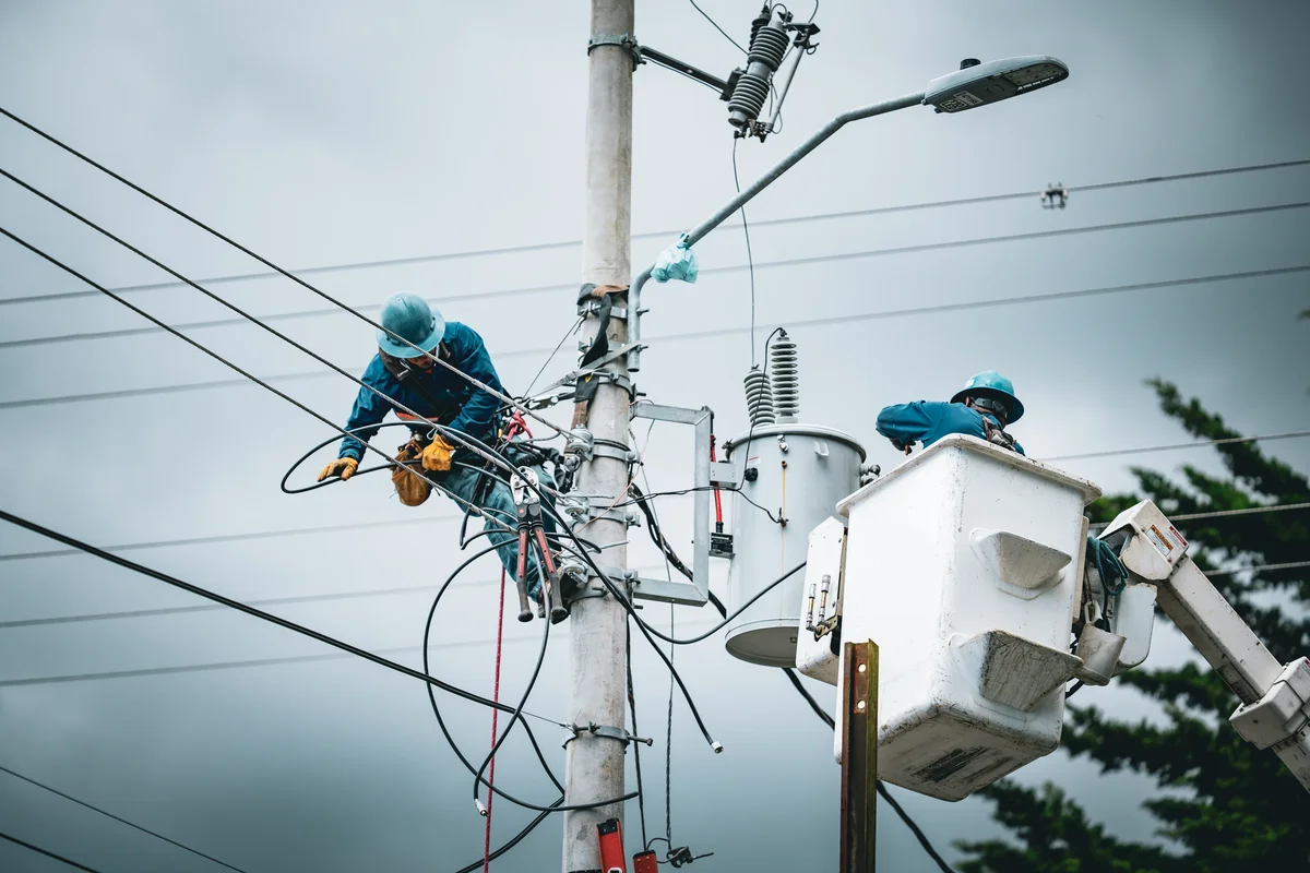
Live-line fanning requires strict potential equalization, dynamic clearance tracking, and verified hot stick dielectric integrity before the first strand contacts the conductor. These three controls eliminate flashover, dropped-tool, and arc-blast incidents.
Establishing Equipotential Bonding Zones
Preformed armor rods are inherently conductive, whether manufactured from aluminum-magnesium-silicon alloy or galvanized steel wire. When a lineman introduces a rod to an energized phase using insulated tools, the free end of the rod effectively becomes part of the live circuit the moment it bridges the air gap. The most common failure in fanning safety is treating the rod as a passive object rather than a floating conductor.
A bonded zone must be established before the rod enters the work envelope. If working from a bucket truck, the platform must be bonded directly to the phase conductor using a rated bond strap capable of withstanding prospective fault current, not just static potential. If working from the ground via hot sticks, the operator must maintain a continuous insulated barrier between their body and the rod’s leading edge. We consistently flag one operational blind spot during field reviews: linemen allowing the trailing end of the rod to swing toward grounded pole hardware or metal cross-arms while the leading end remains energized.
- Bond Strap Rating: Must exceed the local utility’s available fault current; standard static jumpers are insufficient for live fanning.
- Tool Tethering: All fanning heads, rod carriers, and grip mechanisms must be mechanically tied back to prevent dropped-conductor events.
- Zone Boundary: No grounded metallic equipment may enter the rod’s helix radius until the entire assembly is fully seated and electrically equalized.
Maintaining Minimum Approach Distances (MAD)
Minimum Approach Distance is not a fixed measurement during fanning because the operation actively changes the conductor’s geometry. As the armor rod wraps around the span, its mass and helix tension create lateral pull on the conductor. This pull can reduce phase-to-phase clearance by several centimeters, particularly in string-insulator or cross-arm configurations where the conductor already sits close to grounded hardware.
Utility engineers calculate baseline MAD according to system voltage and transient overvoltage factors, typically referencing IEEE 516 or OSHA 1910.269 thresholds. Distribution classes commonly sit at 300mm for 15kV, 600mm for 33kV, and 900mm+ for transmission voltages. However, the dynamic reality of fanning means the operator must recalculate clearance the moment the rod begins wrapping. Wind gusts, bucket drift, and the rotational torque applied to the hot stick all compress the effective air gap.
- Dynamic Clearance Tracking: Treat MAD as a shrinking value during wrap rotation, not a static starting point.
- Phase-to-Phase Risk: Monitor adjacent energized conductors; a pulled conductor can bridge a smaller gap than the original installation tolerance.
- Bucket Repositioning Protocol: If maintaining MAD requires leaning past the boom limit, stop and reposition the platform rather than extending the operator’s body into the hazard zone.
Verifying Dielectric Strength of Hot Sticks
Hot sticks are the only physical barrier separating the lineman from the energized rod during live fanning. Their dielectric reliability degrades silently through UV exposure, micro-cracking, moisture absorption, and repeated flexing at the joint sections. A factory-rated fiberglass or epoxy composite stick that passes an annual hydrostatic or wet-flashover test can still fail immediately after being dragged through a contaminated bucket or left exposed to rain.
Field verification must happen before every shift. Surface inspection should look for chalky white tracking marks, which indicate partial discharge activity, and any delamination along the grip seams. Moisture inside the stick core reduces insulation resistance faster than external dirt alone. The fanning head connection point requires special attention: if the grip slips by even a few millimeters during rotation, the rod can arc across the operator’s wrist guard or drop onto the bucket floor, creating a ground fault path.
- Surface Integrity Check: Reject any stick showing white discharge tracking, deep scratches through the resin layer, or visible core exposure.
- Dryness Verification: Wipe joints with a non-conductive solvent wipe and confirm zero moisture residue before connection.
- Grip Torque Validation: Test the fanning head against the actual rod diameter batch; a loose fit on one coil size invalidates the dielectric assumption for the entire span.
Separate Strands and Fan Without Damaging the Conductor
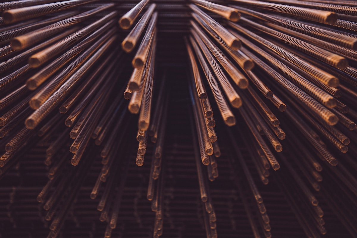
Fanning armor rods without conductor damage requires matching the rod’s pre-formed helical pitch to the cable’s natural lay direction, isolating strands individually, and allowing the hardware’s spring memory to guide placement rather than forcing alignment.
Improper strand isolation is one of the most common causes of premature armor rod failure and conductor surface degradation. When lineworkers peel multiple outer wires outward simultaneously, the balanced tension distribution across the ACSR or AAAC core is disrupted, creating localized kinks that concentrate stress at suspension and tension clamp interfaces. Because conductors vibrate continuously under wind exposure, even minor geometric distortions introduced during fanning can accelerate fatigue failures at fixed points where the armor rod is meant to provide protection.
Strand Isolation Sequence: Preserving Conductor Geometry
The separation process must begin by identifying the conductor’s helix orientation, whether right-hand lay or left-hand lay. Each outer strand should be isolated one at a time using a controlled peeling motion that follows the existing twist pattern rather than opposing it. Pulling against the natural lay reverses the internal stress state of the wire bundle, making the strands more susceptible to work hardening and eventual breakage. Maintaining a consistent bend radius while separating strands prevents micro-cracking, particularly on aluminum-based conductors where repeated flexing exceeds the material’s elastic limit.
- Lay Direction Verification: Confirm right-hand or left-hand helix before engaging the rod to ensure alignment with the conductor’s natural spiral.
- Single-Strand Peeling: Separate one outer wire per motion to keep the core bundle intact and prevent cross-loading between adjacent strands.
- Consistent Bend Radius: Avoid sharp folding points when lifting strands, as tight bends create permanent deformation that compromises tensile strength.
- Helix Continuity: Do not twist isolated strands back toward each other; maintain the original spiral trajectory throughout the fan operation.
Physical fatigue significantly impacts fanning precision during extended elevated work, especially in extreme temperature conditions or during multi-hour daily shifts. Reduced dexterity increases the likelihood of rushed strand manipulation, which often leads to uneven spacing and excessive force application. Armor rods manufactured from high-strength, elastic aluminum-magnesium-silicon alloy or galvanized steel wires are pre-formed with a specific pitch precisely to counter this issue. When the rod’s inherent memory is allowed to guide placement, manual bending effort is minimized, reducing worker fatigue and lowering the probability of surface abrasion on the conductor.
Pitch Matching and Controlled Insertion Mechanics
The pre-formed pitch of the armor rod must correspond closely to the conductor’s lay length. If the rod pitch is too tight relative to the cable, the hardware will bind against the outer strands, creating point loads that scratch or flatten the wire surfaces. If the pitch is too loose, the rod will fail to distribute bending stresses evenly, leaving unprotected sections vulnerable to aeolian vibration and compression damage. Proper insertion requires guiding the leading end into the first isolated strand, then gradually wrapping subsequent turns along the conductor surface so each helix settles into the next available groove.
Overlapping turns or misaligned wraps introduce air gaps between the rod and the cable, which directly undermines the device’s primary function of protecting cables against bending, compression, abrasion, and flash-over. A continuous, gap-free contact surface ensures that mechanical loads are transferred uniformly from the clamp region into the surrounding conductor area. Installers should advance the rod slowly, verifying that each revolution maintains uniform spacing and conforms to the cable diameter without requiring downward pressure or twisting motions.
Forcing a single-helix or double-helix rod onto a conductor with mismatched lay direction reverses the internal stress state. The hardware will attempt to unwind or bind tightly against the wires, destroying both the protective coating on the rod and the outer strand finish on the conductor. Always verify helix orientation and pitch compatibility before beginning the fan sequence.
Select rod material based on conductor composition to prevent galvanic corrosion and ensure compatible flexibility. Aluminum-magnesium-silicon alloy rods are ideal for aluminum conductors because they share similar electrochemical properties and bending characteristics. Galvanized steel rods offer higher tensile strength for heavy-duty applications but require slower, more controlled fanning to avoid scratching softer outer strands during installation.

Seat, Align, and Tension the Rod
Seating, aligning, and tensioning the armor rod requires controlled strand manipulation to maintain conductor geometry, ensure full helical contact, and eliminate high-stress gaps at clamp interfaces.
Controlling Strand Manipulation During Seating
The transition from loose strands to a secured protector depends entirely on how the initial helix is engaged. Linemen often fan multiple strands simultaneously to speed up the process, but this creates immediate alignment instability. When more than three to four strands are lifted at once, the remaining locked helix loses its structural reference point, making it difficult to bring each strip back flush against the conductor surface.
Instead, engage the fanning tool or insulated hot stick head one strand at a time. Wrap the lifted strand fully around the conductor, ensuring the strip lies flat against the previous wrap before releasing tension. This sequential method preserves the helix pitch and prevents localized kinking that could compromise the rod’s ability to distribute bending stress.
- Sequential Engagement: Lift, wrap, and seat one strand per cycle to maintain helix reference geometry.
- Flat-Surface Contact: Each aluminum or galvanized steel strip must lie completely flush against the conductor and the adjacent wrap to prevent air pockets.
- Conductor Surface Protection: Avoid dragging lifted strands across exposed strand filaments, which can scratch the aluminum and reduce corrosion resistance before the rod is even fully seated.
Alignment Tolerances and Mechanical Tension Standards
Once all strands have been wrapped, the armor rod must be pulled tight enough to close helix gaps without distorting the conductor or deforming the protector strips. Proper tension ensures the rod functions as a unified sleeve rather than a collection of loose wraps. The protector should extend slightly beyond the clamp jaw—typically covering the full grip length plus a minimum margin—to guard against bending fatigue at the termination point.
Misalignment during the tension phase is rarely visible from the ground, but it directly impacts long-term performance. Gaps between helix turns allow the conductor to micro-move under thermal expansion and wind load, accelerating abrasion at the clamp boundary. Uniform spacing also ensures consistent electrical contact and mechanical load distribution across all protected strands.
- Overlap Consistency: Maintain uniform turn-to-turn overlap across the entire protector length; uneven spacing creates weak points where conductor wear initiates.
- Axis Parallelism: Wrapped strands must run parallel to the conductor centerline. Twisted or crossed wraps introduce torsional stress that can damage stranded conductors.
- Gap Elimination: The finished armor rod should show no visible light penetration between helix layers, confirming full seating and maximum abrasion coverage.
Final Checks and Common Fanning Mistakes
A properly finished armor rod installation requires controlled gap distribution, flush rod ends, and full conductor contact. Any deviation creates stress points that accelerate fatigue failure.
Detecting Helix Gaps and Uneven Spacing
When the individual rods in a preformed assembly fan out unevenly, the entire damping mechanism loses effectiveness. A common failure mode occurs when installers accept visible gaps as cosmetic defects rather than functional red flags. In reality, irregular spacing shifts the load transfer away from uniform conductor protection toward concentrated pressure points.
Aeolian vibration travels through the conductor at predictable frequencies, and the armor rod must respond as a continuous system rather than a collection of loose strands. If certain sections sit closer together while others leave open windows, those gaps become initiation sites for wire fatigue. We have seen field reports where uneven fanning led to premature strand separation near suspension clamps, defeating the purpose of the installation entirely.
Do not mistake tight winding for proper installation. Gaps may appear acceptable visually, but if the helix does not distribute evenly across the designated span, the rod cannot absorb vibration uniformly.
Correcting Over-Fanning at Rod Ends
Over-fanning happens when installers spread too many strands at once during the final wrap, creating an uncontrolled flare at the rod terminations. This mistake is especially risky when working at height or in cold conditions where dexterity decreases. The result is a bundle of loose wires that can catch on hardware, snag during inspection, or unravel under sustained wind exposure.
The correct approach requires controlled incremental fanning rather than aggressive spreading. Each strand should remain parallel to its neighbors throughout the application, and rod ends must terminate cleanly against the preceding wrap. Loose ends create a mechanical weak point where vibration energy concentrates, increasing the likelihood of conductor wear at the clamp boundary.
- Pass Criteria: All rod ends are tightly wound, seated flush, and resistant to manual unraveling.
- Fail Indicator: Any strand protrudes beyond the helix termination or can be pulled free without tension on adjacent rods.
Validating Full Seating on Conductor Surface
Visual confirmation is necessary but insufficient. Full seating means every rod segment maintains continuous contact with the conductor profile, with no lifted sections or air pockets between the armor and the cable. When seating is incomplete, the rod cannot effectively distribute bending stress across the protected zone.
We inspect this by running a gauge along the installed assembly to verify that the inner diameter conforms to the conductor outer diameter. Any rocking motion or visible separation indicates that the rod was either undersized or improperly tensioned during application. In our manufacturing facility, dimensional accuracy is enforced through automated machinery, which reduces the risk of receiving products that fail this checkpoint before they ever reach the job site.
The galvanizing finish also plays a role here. A rough or uneven coating can prevent smooth seating, while a consistent hot-dip finish allows the rod to conform precisely to the conductor. This is why we prioritize surface quality alongside dimensional tolerances in our production process.
| Inspection Area | Common Fanning Mistake | Final Verification Step | Line Integrity Impact |
|---|---|---|---|
| Strand Handling | Fanning all strands simultaneously without securing the bundle | Fan in controlled increments while maintaining parallel alignment throughout the application | Twisted strands reduce mechanical grip and can abrade the conductor surface |
| Dimensional Fit | Installing armor rods that do not match the specific conductor outer diameter | Confirm inner rod diameter matches the conductor O.D. prior to initiating the fanning process | Incorrect sizing causes slippage, ineffective vibration damping, or localized pressure damage |
| Alignment & Spacing | Leaving uneven gaps or irregular overlaps between individual strands | Ensure consistent gap spacing and full, uniform coverage along the designated span | Uneven load distribution creates stress concentration points and accelerates fatigue breaks |
| Surface Integrity | Overlooking sharp edges or burrs on the galvanized hardware | Verify hot-dip galvanizing finish complies with ISO 1461 standards and coating thickness exceeds 85 microns | Rough surfaces or insufficient coating compromise corrosion resistance and increase the risk of conductor wear |
| Termination Security | Allowing loose or unsecured rod ends after installation | Confirm all ends are tightly wound, seated flush, and resistant to manual unraveling | Loose ends can unravel under aeolian vibration, exposing the conductor to unprotected fatigue |
Conclusion
Fanning armor rod demands control, not speed. Separate strands evenly, match conductor diameter to the rod rating, and seat the helix flush before tensioning. Our field teams flag over-fanning rod ends as the top cause of crushed conductor surfaces. That mistake introduces stress points and kills service life. Verify hot stick dielectric strength and inspect rods for transport deformation before you begin. Proper fan width ensures the grip stays uniform across every strand.
- Confirm your crew understands the MAD requirements for the voltage class.
- Treat our engineering group as your technical backup for early design questions or sizing uncertainties with zero obligation.
- Review the alignment checklist before energizing the line.
Frequently Asked Questions
How to select correct armor rod size?
Select the armor rod based on the exact outer diameter of the conductor being protected. Using an incorrect size can lead to loose fitting, reduced mechanical strength, or damage to the conductor strands. Refer to the rod specification chart to match the conductor gauge before purchase. Proper sizing ensures optimal contact pressure and effective load transfer.
What materials are used in armor rods?
Most preformed armor rods are manufactured from high-strength aluminum alloy or galvanized steel wire. Aluminum alloys are preferred for aluminum conductors to prevent galvanic corrosion and maintain weight compatibility. Steel variants offer higher tensile strength for specific heavy-duty applications. Material choice depends on the conductor type and environmental requirements.
How do you fan an armor rod?
Fan one wire strand at a time, alternating sides to maintain balance. Start at the center mark and work outward toward the grip ends. Ensure each strand lies flat against the conductor without crossing or overlapping adjacent wires. Proper fanning distributes stress evenly and prevents conductor damage during operation.
Do armor rods prevent conductor vibration?
Armor rods are designed to dampen aeolian vibration by adding mass and friction to the conductor surface. They reduce fatigue at suspension points where standing waves commonly cause strand breakage. While they do not eliminate all vibration types, they significantly extend conductor life in exposed spans. Regular inspection confirms the rod remains effective over time.
When should you replace damaged armor rods?
Replace armor rods immediately if strands are broken, kinked, or separated from the main body. Damage reduces the rod’s ability to distribute stress and dampen vibration effectively. Corrosion that compromises structural integrity or coating protection also necessitates replacement. Installing a new rod restores full protection to the conductor at critical hardware points.