
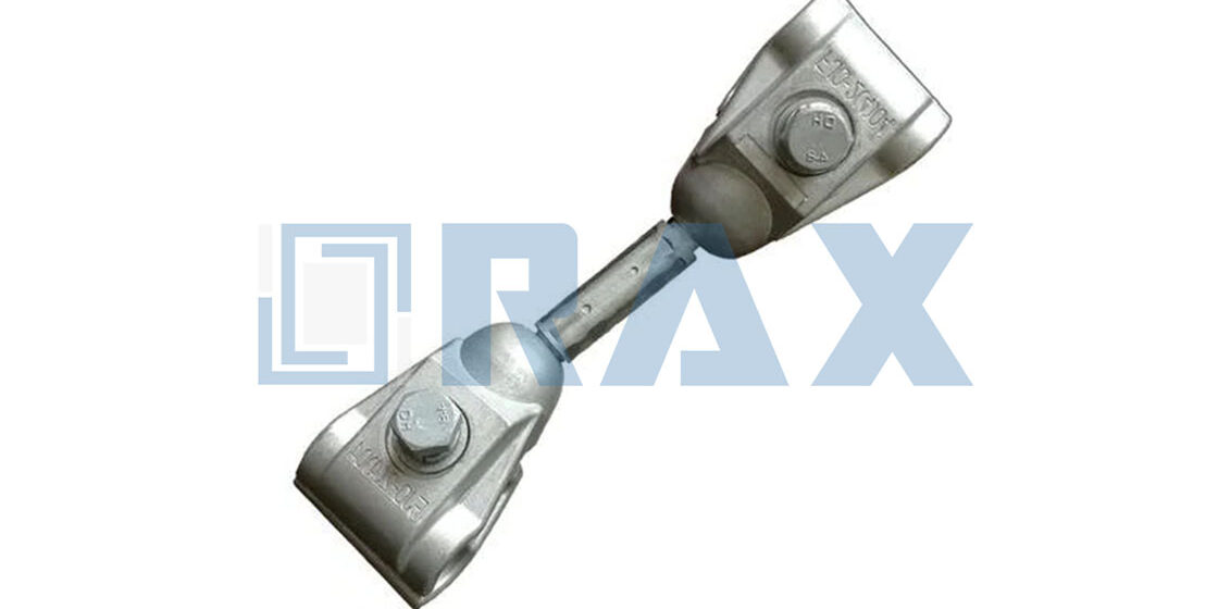
Wake-induced oscillation turns bundled conductors into a mechanical fatigue nightmare if the damping ratios miss the mark. Most procurement teams focus heavily on clamp grip strength, yet the real failure mode often stems from mis-sized spacer damper subspan oscillation control that fails to match the specific vortex shedding frequency of the site. Get this wrong, and the hardware actually introduces stress points rather than mitigating them.
Field testing on quad and triple bundles proves that correct spacing choices improve damper performance by a factor of four to five times. That is not a marginal efficiency gain; it is the difference between a 40-year asset life and premature conductor fatigue at the suspension points. Generic “standard” spacing charts rarely account for the aerodynamic drag variances found in real-world terrain.
This guide breaks down the protocols for collecting conductor dynamic load parameters, mapping bundle compatibility charts, and verifying hot-dip galvanizing thickness for corrosion profiles. You will leave with the specific sizing criteria needed to withstand short-circuit loads and maintain bundle geometry under severe wind conditions.
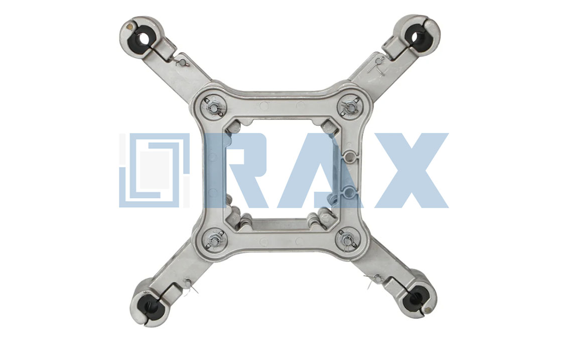
Collect Conductor Dynamic Load Parameters
Accurate dynamic load parameter collection prevents catastrophic subspan oscillation and ensures long-term grid reliability under variable wind loads.
Bundle Geometry and Aerodynamic Drag Mapping
Establishing baseline aerodynamic inputs begins with mapping how your chosen bundle configuration interacts with wind vectors. Multi-conductor bundles generate complex wake interference patterns that fundamentally alter local drag coefficients. Engineers must model these aerodynamic profiles to predict where turbulent eddies will concentrate stress along the transmission corridor. Overlooking these geometric variables inevitably leads to underestimated wind loads and accelerated hardware fatigue.
Our engineering team maps these aerodynamic profiles during the prototype phase to ensure every control grid and spacer damper aligns precisely with your site-specific wind tunnel data. When standard configurations fall short, our custom mold development capabilities allow us to fabricate tailored hardware that accommodates non-standard bundle arrangements without compromising structural integrity.
Conductor Tension and Mass Calibration Steps
Before hardware installation, field engineers must execute rigorous mass-per-meter verification and tension calibration sequences. Conductor weight directly dictates sag-tension relationships, which in turn govern the mechanical load transferred to suspension clamps and dead-end grips. Calibration requires cross-referencing manufacturer delivery certificates with independent field tension meters to eliminate cumulative calculation errors.
- Mass Verification: Confirm linear density against rated tensile strength specifications to ensure grip force calculations remain within safe operational margins.
- Tension Metering: Deploy calibrated hydraulic or digital tension indicators during stringing operations to capture real-time load distribution.
- Sag Profiling: Apply tension correction factors for ambient temperature differentials to prevent over-stressing attachment points during thermal expansion cycles.
We verify mass calibration against the specified RTS to prevent premature fatigue at suspension points. Our automated clamping machinery guarantees consistent dimensional accuracy across bulk orders, ensuring that field-calibrated tension values translate directly into reliable hardware performance without requiring on-site machining adjustments.
Subspan Length Ratio Optimization Parameters
Optimizing the subspan length ratio requires balancing mechanical stiffness against aerodynamic flexibility. Setting interval distances too closely increases torsional rigidity, which can inadvertently transfer destructive vibrational energy into adjacent hardware components. Conversely, excessive spacing reduces damping effectiveness, leaving conductors vulnerable to low-frequency interphase collisions. The optimal ratio hinges on matching hardware elasticity to the expected wind shear profile at your project elevation.
In our facility, we adjust spacer intervals dynamically during dynamic cycle testing to match the optimal damping ratio for your specific grid layout. This iterative calibration process allows utility buyers to secure flexible MOQs and rapid sample prototyping, ensuring that your approved hardware samples perform exactly as engineered before committing to full-scale production runs.
Vortex Shedding Frequency Threshold Calculations
Calculating vortex shedding thresholds is critical for identifying resonance conditions that trigger aeolian vibration. As wind flows perpendicular to the conductor surface, it generates alternating low-pressure vortices downstream. When the frequency of these vortices aligns with the natural mechanical frequency of the subspan, amplitude magnification occurs rapidly. Engineering models must therefore factor in wind velocity ranges, conductor diameter, and atmospheric turbulence intensity to establish safe operating boundaries.
Our in-house IEC 120 load testing explicitly monitors these frequency thresholds to validate that our control grids and dampers dissipate vibrational energy effectively before resonance propagates through the transmission line. By integrating precision hot-forged manufacturing with validated damping characteristics, we deliver turnkey solutions that meet stringent utility reliability benchmarks while streamlining your procurement workflow.
| Parameter | Specification Range | Validation Standard | Manufacturing Edge | Procurement Benefit |
|---|---|---|---|---|
| Conductor Diameter & Tensile Load | 11.4–35 mm / Up to 40 kN | IEC 120 In-House Load Testing | Hot-forged precision with ±1mm automated tolerance | Custom mold development for non-standard bundle configurations |
| Torsional & Radial Stiffness | KT: 800–1200 daN·m/rad / AK: 70,000–90,000 daN/m | SGS-Certified Vibration Fatigue Analysis | ISO 1461 Hot-Dip Galvanizing exceeding 85μm mean thickness | Guaranteed corrosion resistance for extreme climate utility tenders |
| Subspan Length & Wind Response | 30–70 m span / Damping Ratio: 0.05–0.15 | IEC 120 Dynamic Cycle Testing | 10-Person QC Team with mandatory double-review protocol | Flexible MOQ & rapid sample prototyping for project-specific grids |
| Clamp Grip Force & Installation Torque | Slip Load: >20% RTS / Torque: 45–85 Nm | IEC 120 Gauge & Load Testing | Automated machinery ensures consistent dimensional accuracy | OEM design integration with turnkey installation toolkits |
| Structural Alloy & Surface Coating | Steel Grade: Q355 / Zinc Thickness: ≥85μm | ISO 1461 & SGS Material Certification | Advanced hot-forging delivers superior strength vs traditional casting | Direct factory pricing with global certification readiness |
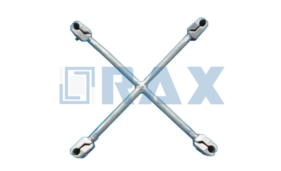
Evaluate Environmental Corrosion Exposure Profiles
Evaluating environmental corrosion exposure profiles for pole line hardware requires strict alignment between material metallurgy, coating thickness verification, and regional utility mandates. Subspan oscillation control grids and clamp systems must be engineered to withstand localized atmospheric chemistry without degrading structural integrity. This demands standardized hot-dip galvanizing protocols, verified alloy grain structures, and rigorous in-house gauge testing before bulk shipment.Corrosion failure in transmission hardware is a procurement risk, not an engineering variable. Verify ISO 1461 compliance, enforce 85-micron minimum coating thickness, and demand double-reviewed QC logs prior to PO approval.
Marine Salt Spray Corrosion Resistance Grading
Coastal and offshore utility corridors introduce aggressive chloride ion penetration that rapidly accelerates pitting and stress corrosion cracking in standard steel fasteners. Industry benchmarks typically classify marine-grade corrosion resistance using ASTM B117 salt spray testing cycles, but practical field longevity depends entirely on coating adhesion and substrate preparation rather than isolated lab hours. For B2B procurement, relying solely on salt spray hour counts without cross-referencing actual coating microstructure leads to premature asset replacement. We specify hot-dip galvanizing processes that metallurgically bond zinc layers to the base steel, ensuring the hardware remains structurally sound even when surface oxidation occurs.
- Atmospheric Zone Classification: Match hardware grades to C4 (industrial), C5-I (coastal), or C5-M (marine off-shore) ISO 12944 categories based on projected line route exposure.
- Chloride Mitigation: Specify continuous zinc-iron alloy layers that prevent electrolytic breakdown under prolonged salt fog conditions.
- Procurement Validation: Require mill test reports correlating batch numbers with documented salt spray performance curves.
Hot-Dip Galvanizing Thickness Verification Protocols
Surface coating thickness is the primary determinant of service life for overhead line hardware exposed to corrosive elements. While many manufacturers rely on spot-check sampling, a single thin zone on a guy clamp or control grid anchor point compromises the entire assembly. Our facility enforces ISO 1461 compliant hot-dip galvanizing technology, guaranteeing a smooth, bright finish with a mean coating thickness exceeding 85 microns. This threshold significantly outperforms standard electro-galvanized finishes, which typically range between 5 to 15 microns and fail rapidly in humid or saline environments.
- In-House Gauge Testing: All production stages undergo mandatory thickness verification per IEC 120 standards using calibrated magnetic induction gauges.
- Dual-Review Inspection: A dedicated 10-person QC team executes a mandatory double-review process. Every single component is inspected twice before packaging to eliminate thickness variance outliers.
- Certification Requirements: Demand SGS-verified coating reports attached to each shipping manifest for full supply chain transparency.
Clamp Alloy Composition for Extreme Climates
Thermal cycling in extreme climates causes expansion and contraction that can fracture brittle cast metal components over time. Traditional casting methods often leave internal porosity and uneven grain structures, creating weak points where corrosion initiates. We utilize advanced hot-forging techniques that realign the steel grain flow along the contour of the clamp, delivering superior tensile strength and fatigue resistance compared to casting. This manufacturing edge is critical for subspan oscillation control grids subjected to continuous wind-induced vibration and temperature fluctuations ranging from -40°C to +70°C.
- Grain Structure Alignment: Hot-forging preserves material continuity, preventing intergranular corrosion pathways common in cast alternatives.
- Custom Mold Development: OEM/ODM capabilities allow us to transform client drawings into finished products with precise alloy compositions tailored to specific thermal stress profiles.
- Load Testing Validation: Rigorous mechanical load testing confirms that alloy composition meets or exceeds required breaking load specifications under cyclic stress conditions.
Regional Utility Corrosion Standard Compliance Mapping
Global transmission networks operate under divergent regulatory frameworks, meaning a one-size-fits-all corrosion specification will result in tender rejections or compliance failures. Utility procurement teams require hardware that aligns precisely with local environmental baselines and maintenance budgets. Rax Power maps our manufacturing outputs directly to these regional demands, adjusting alloy grades, coating thickness tolerances, and packaging standards to satisfy local regulatory bodies.
- Russia & CIS Regions: Specialized in high-breaking load requirements and enhanced anti-corrosion treatments designed for extreme freezing temperatures and permafrost ground conditions.
- South America: Focused on high-tier quality standards and rigorous UV/ozone resistance to match regional utility specifications for tropical and subtropical overhead line infrastructure.
- Southeast Asia: Deep expertise in local tender requirements, manufacturing standards, and high-humidity salt spray mitigation protocols mandated by ASEAN power authorities.
Map Conductor Bundle Compatibility Charts
Bundle Configuration and Geometry Mapping
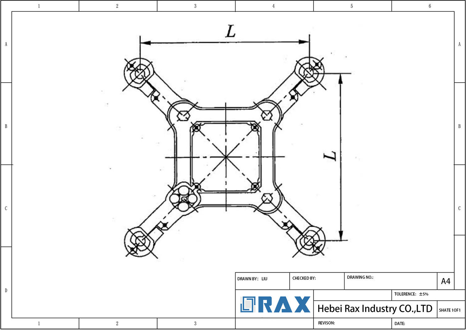
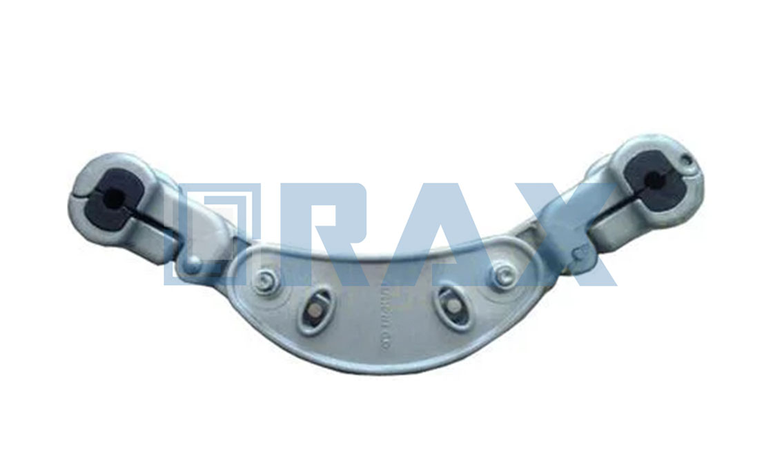
The primary function of a Conductor Bundle Compatibility Chart is to map specific bundle configurations—twin, triple, quad, or hexagonal—to the appropriate frame geometry of spacer dampers or spacers. This cross-referencing is critical because the mechanical advantage and aerodynamic stability of the bundle depend entirely on the precise spatial arrangement of the sub-conductors. When utilizing these charts, engineers must verify that the selected hardware frame supports the exact sub-span distances required by the line design.
- Horizontal or Vertical Twin Bundles: Typically require rigid frame styles designed to maintain a fixed separation distance, often ranging from 400mm to 600mm depending on voltage class.
- Three-Conductor Bundles: Demand triangular frame geometries that equalize the spacing between all three phases to prevent asymmetric wake-induced oscillations.
- Quad and Hexagonal Bundles: Utilize square or hexagonal frame configurations; compatibility charts must specify the “diagonal” versus “side” spacing dimensions to ensure proper fitment within the suspension clamp assembly.
Conductor Diameter to Clamp Interface Correlation
A compatibility chart must strictly define the allowable conductor diameter range for each clamp assembly. The interface between the conductor and the clamp is the most sensitive point of failure; if the viscoelastic bushing is sized incorrectly, it either fails to grip the conductor adequately (causing slippage) or exerts excessive point-load pressure (crushing the aluminum strands). Standard engineering practice requires referencing the chart to align the specific conductor code (e.g., ACSR “Diameter” ranges) with the designated clamp size code.
The chart should differentiate between “standard” and “reinforced” clamp bodies. For larger diameters exceeding 35mm, the compatibility matrix must specify whether the clamp utilizes elastomer bushings or preformed armor rods to distribute the compressive load. This distinction is vital for maintaining the damping performance required to control aeolian vibration and sub-span oscillation.
Short-Circuit and Restoration Load Verification
Beyond static dimensions, the compatibility chart must indicate the frame’s capacity to withstand electromagnetic pinch forces during short-circuit events. The selected hardware geometry must be capable of maintaining conductor separation during high-current faults and subsequently restoring the bundle to its original geometry once the fault clears. Charts typically categorize frames by their “Short-Circuit Current Withstand” rating (kA), which is directly influenced by the bundle spacing and the stiffness of the frame structure.
When cross-referencing data, ensure that the chart confirms the frame’s ability to handle the calculated mechanical loads resulting from ice and wind shedding. A strong compatibility mapping will list the maximum recommended sub-span length for each bundle arrangement to prevent dynamic instability under extreme environmental loading.
Calculate Subspan Natural Frequencies
Accurately determining natural frequencies is the primary defense against wake-induced oscillation in bundled conductors, ensuring spacer dampers are positioned at optimal nodal points to maximize energy dissipation.
Fundamental Frequency Mechanics
Calculating the natural frequency of a conductor subspan requires a precise understanding of the tension-to-mass relationship. The fundamental frequency ($f_n$) is not a fixed value but a dynamic property dependent on the mechanical state of the line. In engineering practice, this is derived using the taut string approximation, where the frequency is inversely proportional to the span length and directly proportional to the square root of the tension over the unit mass. When dealing with multi-conductor bundles, the effective mass must account for the combined weight of all sub-conductors plus the mass of attached spacer dampers, as even small mass additions can slightly shift the resonant bands.
- Tension ($T$): Must be measured at the average ambient temperature of the installation site, as frequency shifts of 0.5 Hz to 1.0 Hz can occur between summer sag and winter tension conditions.
- Mass per Unit Length ($m$): Calculated based on the specific conductor diameter (e.g., ACSR or AAAC) and ice loading coefficients if applicable.
- Span Length ($L$): The distance between two adjacent suspension points or spacer dampers. Unequal subspans create multiple resonant peaks that must be individually mapped.
Subspan Ratio Optimization
Research indicates that equal subspan lengths often yield suboptimal damping performance. Establishing a non-dimensional characteristic relating the ratios of adjacent subspans to nodal positions allows for the disruption of standing waves. By deliberately varying subspan lengths (e.g., employing a 0.6:0.4 ratio instead of 0.5:0.5), the system introduces mismatch between the natural frequencies of adjacent spans. This detuning prevents the energy transfer required for sustained oscillation. Field tests demonstrate that the performance of a spacer damper in a given mode can be improved by a factor of four to five times simply by the correct choice of spacings, rather than changing the hardware itself.
Aerodynamic Damping and Resonance Bands
The calculation of natural frequencies must be cross-referenced with the vortex shedding frequency of the wind. If the calculated natural frequency of the subspan falls within the “unstable window” of wind-induced vortex shedding (typically 0.5 Hz to 10 Hz for transmission lines), resonance occurs. Aerodynamic damping coefficients serve as the counter-force; they represent the energy dissipated by the conductor movement through the air. However, in bundled conductors, the wake effect from the windward conductor reduces aerodynamic damping for the leeward conductor, effectively narrowing the safety margin.
To validate the design, engineers utilize the logarithmic decrement ($\delta$) to quantify damping efficiency. A target logarithmic decrement of 0.05 to 0.10 is typically required for stability in critical wind zones. The placement of spacer dampers with viscoelastic bushings is intended to increase this mechanical damping. If the calculation shows that the natural frequency intersects the wind energy input frequency and the system damping is below the critical threshold, the subspan spacing must be recalculated to shift the resonant frequency outside the dominant wind excitation band.
Define Technical Sizing Parameters
Optimal sizing aligns mass, inertia, and torque tolerances with dynamic load calculations and environmental exposure profiles.
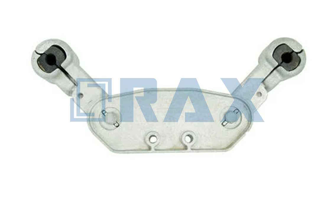
Defining technical sizing parameters for overhead line hardware requires more than selecting standard physical dimensions. Engineers must calibrate mass distribution, moment of inertia, and structural cross-sectional area to match calculated dynamic frequency ranges and site-specific environmental loads. When sizing vibration control devices or pole line fasteners, the primary objective is ensuring that mechanical resonance frequencies fall outside operational wind spectra while maintaining sufficient ultimate holding strength under extreme shear and tension. Incorrect parameter mapping leads to accelerated conductor fatigue, anchor withdrawal, or premature galvanizing failure.
Calibrating Mass Distribution and Moment of Inertia
Vibration suppression hardware relies on precise mass allocation to target specific sub-span oscillation frequencies. The device must counteract aerodynamic drag forces without introducing excessive inertial loads that could distort bundle geometry. Engineers calculate the required moment of inertia by mapping the conductor’s dynamic mass against the expected aeolian vibration bandwidth. Viscoelastic integration within the hardware must restore the original bundle posture following high-impact events, such as short-circuit currents or ice accumulation, without permanent deformation.
Aligning Anchor Specifications with Soil and Torque Benchmarks
Utility pole anchoring parameters demand rigorous correlation between soil classification, installation torque, and load capacity metrics. For helical systems, distinguishing between soil Class 5 and Class 6 directly dictates shaft diameter, pitch depth, and bearing plate surface area. No-wrench screw anchors require pre-calculated pull-out thresholds to prevent catastrophic foundation failure during storm-induced tension spikes. Similarly, sizing a 3/4-inch guy anchor necessitates verifying its ultimate holding strength against regional utility codes, factoring in soil displacement resistance and lateral shear limits. Dimensional consistency remains critical; automated production maintains strict ±1mm tolerances across alley arms and braces, ensuring bolt-hole alignment under heavy strain.
- Torque Application Limits: Installation torque must strictly adhere to specified yield thresholds to avoid thread stripping or premature galvanizing micro-fractures.
- Corrosion Allowance Sizing: Protective coatings must meet ISO 1461 standards, requiring a mean thickness exceeding 85 microns to preserve structural cross-sections in marine or industrial environments.
- Geotechnical Bearing Ratios: Helical anchor diameter and flight pitch must scale proportionally to Class 5 versus Class 6 soil density metrics to prevent rotational settlement.
- Dynamic Safety Factors: Guy anchor load ratings must exceed maximum design tension by a minimum safety factor of 1.5 to account for unmodeled wind gusts and ice loading.

Specify Clamp System Material Grades
Selecting the correct clamp alloy and elastomer durometer prevents conductor surface degradation and structural slippage under dynamic wind and thermal loading.
When specifying clamp system materials, the primary engineering failure occurs when the fixture alloy lacks sufficient yield strength relative to the conductor tensile rating, or when the internal gripping medium is too soft to resist shear forces. Utility engineers must match clamp metallurgy and bushing hardness precisely to the conductor profile and expected mechanical load to ensure long-term grid reliability.
Base Alloy Selection and Structural Integrity
Clamps handling high-tension or bundled conductors require aluminum alloys with documented minimum yield strengths exceeding 200 MPa. Standard cast aluminum components frequently fracture under dynamic galloping conditions due to inherent porosity. Wrought aluminum alloys, specifically heat-treated grades meeting ASTM B221 specifications, deliver the necessary structural rigidity. For steel-reinforced conductors, clamps often utilize forged steel bases to prevent galvanic corrosion while maintaining precise clamp-on torque specifications. The manufacturing method fundamentally alters fatigue life: hot-forged components establish a continuous grain flow that resists crack propagation far better than sand-cast alternatives, directly increasing the ultimate breaking load capacity.
Elastomer Bushing Hardness and Conductor Matching
The interface between the clamp body and the conductor dictates long-term performance. Elastomer bushings must be formulated to balance grip retention with conductor surface preservation. Shore A hardness typically ranges from 50 to 70 depending on the conductor material composition. Softer conductors, such as AAAC or composite variants, require lower durometer compounds to prevent indentation and embedded fiber damage during thermal expansion cycles. Heavier ACSR or AAC bundles demand higher durometer viscoelastic materials that maintain clamping force across wide temperature fluctuations without cold-flow or permanent deformation.
- Shore A 50–60: Optimized for soft-strand composite or AAAC conductors to distribute contact pressure evenly and prevent surface marring.
- Shore A 65–70: Designed for heavy ACSR or AAC bundles requiring maximum shear resistance and vibration energy dissipation through controlled hysteresis.
- Viscoelastic Formulation: Ensures the bushing returns to original geometry after short-circuit or ice-load events, maintaining bundle spacing integrity.
Load Ratings, Coating Continuity, and Verification Protocols
Material grade specification must account for the operational environment and mechanical stress thresholds. Structural metal components require protective metallurgical barriers that survive transport, installation torque, and decades of field exposure. Hot-dip galvanizing remains the baseline standard, with coating thickness strictly maintained above 85 microns per ISO 1461 requirements to guarantee zinc-to-steel adhesion. In high-stress applications, every fastener—from double-arming bolts to secondary racks—must undergo independent gauge and load verification per IEC 120 parameters before deployment. This double-review process ensures that galvanizing continuity does not compromise electrical isolation or mechanical shear capacity under maximum design wind loads.
Correct material alignment eliminates the need for field re-torquing and extends the maintenance cycle to decades. By matching alloy yield limits to conductor tensile strength and calibrating bushing durometers to strand softness, engineers ensure that transmission hardware performs as a unified mechanical system rather than a collection of mismatched components.

Set Installation Spacing Interval Limits
Installation spacing is not a standardized distance but a calculated limit derived from the conductor’s tension-to-mass ratio and the damper’s specific stiffness to detune natural frequencies.
Establishing precise installation spacing intervals is the primary defense against sub-span oscillation (SSO) and aeolian vibration in bundled conductors. The spacing interval essentially defines the length of the vibrating string between two support points. If the interval is too wide, the natural frequency of the sub-span drops into the critical range of wind-induced excitation (typically 0.5 Hz to 3 Hz for SSO), leading to high-amplitude conductor movement and potential clashing. Conversely, excessively narrow intervals increase material costs and weight without offering proportional benefits in damping efficiency. The optimal interval limit is determined by solving the wave equation for the specific conductor type and tension, ensuring the sub-span frequency remains decoupled from the dominant vortex shedding frequencies.
The End-Span vs. Inner-Span Rule
A critical distinction often overlooked in field installation is the difference in boundary conditions between suspension points and spacer dampers. The suspension clamp at the tower acts as a near-fixed boundary, whereas the spacer damper behaves as an elastic support with distinct rotational stiffness. Due to this disparity in boundary rigidity, applying uniform spacing across the entire span creates a “weak link” at the ends. To prevent resonant buildup in the outer sections, the end-spans—the intervals between the suspension clamp and the first spacer damper—must be shorter than the inner-spans.
Adhere strictly to the 0.6 to 0.7 ratio rule: set the installation spacing for end-spans to approximately 60-70% of the calculated inner-span distance. This compensation accounts for the higher stiffness at the tower and prevents the end sub-spans from acting as resonant levers that accelerate fatigue at the suspension points.
Variables Defining Interval Limits
Calculating the maximum permissible spacing requires analyzing the interaction between the mechanical properties of the conductor and the damper. The limit is reached when the damping efficiency of the spacer damper can no longer dissipate the energy input from wind-induced vibration. Engineers must consider the following dynamic parameters when setting these limits:
- Conductor Tension (H): Higher tension increases wave velocity, raising the natural frequency of a given span. As tension varies with temperature and loading, spacing limits must be calculated for the “everyday temperature” (EDT) scenario, not the maximum operating tension, to ensure protection during the most common wind conditions.
- Conductor Mass per Unit Length (m): Heavier conductors (e.g., ACSR “Drake” vs. smaller ACSR “Rail”) possess higher inertia, shifting natural frequencies downward. Consequently, heavier bundles typically require shorter maximum spacing intervals to maintain frequencies above the dangerous threshold.
- Damper Arm Stiffness: The bending stiffness of the spacer damper’s frame determines how effectively it decouples adjacent sub-spans. The installation limit must be short enough so that the damper can mechanically restore the bundle geometry against the aerodynamic forces without excessive deflection.
Never average the spacing for uneven terrain. If a span length varies or involves angle changes, recalculate the intervals for that specific section. Using a standard spacing derived from a level tangent span for a steeply inclined span can result in vertical geometry mismatches, causing the lower damper to bear excessive static weight and losing damping capability.
Verify Damping Coefficients Against Standards
Validating damping coefficients requires strict IEC wind-profile alignment, rigorous in-house dynamic testing, and audit-ready utility compliance documentation to prevent long-term conductor fatigue.
IEC Vibration Damping Performance Benchmark Alignment
Aeolian vibration manifests as high-frequency, low-amplitude oscillations that rapidly induce mechanical fatigue at suspension points. Matching your hardware to IEC 60873 wind profiles ensures the damping curve captures energy exactly where the conductor experiences maximum stress. Misaligned damping characteristics simply shift fatigue points higher up the span, delaying maintenance but accelerating structural degradation.
We design our spiral dampers to follow standard logarithmic decrement requirements, ensuring the system absorbs oscillation energy without introducing parasitic tension spikes. This alignment is critical for multi-bundle configurations where aerodynamic interference patterns change rapidly across different wind angles.
In-House Load Testing Protocol Validation
Paper specifications rarely reflect the chaotic reality of long-term grid operation. Our engineers run continuous dynamic load simulations that mimic decades of wind exposure within compressed laboratory cycles. These protocols verify grip integrity under cyclic loading, ensuring the core mechanism retains its energy dissipation properties without hardening or cracking.
Every production batch undergoes gauge verification before dispatch. We cross-reference our internal load curves against manufacturer torque recommendations to eliminate installation variances that typically compromise damping efficiency in the field.
Damping Coefficient Tolerance Range Verification
Real-world damping performance inevitably fluctuates due to temperature shifts, conductor aging, and environmental contamination. Establishing a strict tolerance band during manufacturing prevents the system from either under-damping or over-damping, both of which transfer excessive shear loads to the clamp body.
- Material Consistency: Raw alloy composition directly impacts the stiffness modulus, requiring batch-level spectroscopic analysis.
- Manufacturing Precision: Automated bending and forming reduce geometric deviations that would otherwise skew the effective damping radius.
- Environmental Sealing: Protective coatings prevent moisture ingress into the core mechanism, preserving the intended coefficient across operational lifespans.
Utility Reliability Benchmark Compliance Documentation
Modern utility tenders demand unbroken traceability from raw material intake to final dispatch. A thorough compliance dossier must include independent third-party certification, detailed test reports, and full material passports that align with regional grid codes.
Our quality control framework generates standardized documentation packages ready for international utility audits. By maintaining transparent records of every test cycle and coating thickness measurement, we optimize the procurement approval process and reduce pre-installation compliance friction for global project managers.
| Standard/Parameter | Verified Specification | Testing Protocol | Engineering Benefit | Commercial/Manufacturing Edge |
|---|---|---|---|---|
| IEC 60873 / IEEE 738 (Aeolian Vibration) | Damping coefficient ≥ 0.05 N·m/rad | In-house dynamic load testing & gauge verification (IEC 120 compliant) | Prevents conductor fatigue and clamp slippage under steady wind conditions | Custom mold development for specific damping curves; flexible MOQ for pilot runs |
| CIGRE TB 387 / IEEE 524 (Subspan Oscillation) | Validated energy dissipation rate for bundle spacing 400–800mm | Staggered positioning simulation & torsional stability validation | Mitigates inter-subspan clashing and reduces long-term wear on spacers/dampers | OEM engineering support with CAD-to-production turnaround; standards aligned with utility tender requirements |
| ISO 1461 (Hot-Dip Galvanizing) | Mean coating thickness > 85 microns; smooth bright finish | Double-review QC inspection by 10-person team; 100% pre-packaging verification | Maintains consistent damping performance over 30+ year lifecycle without degradation | Automated production ensuring high dimensional accuracy; SGS third-party certification included |
| Project-Specific Assembly Guidelines | Pre-formed grip tension calibrated to manufacturer torque specs | Rigorous load testing & gauge testing per IEC 120 before dispatch | Eliminates field installation errors that compromise damping efficiency | Technical documentation & installation guides provided; dedicated support for global markets |
Conclusion
Specifying spacer dampers is strictly a physics exercise, not a generic hardware selection. You must match the unit’s mass and clamp geometry directly to the conductor’s tension and bundle spacing to avoid fatigue. If you ignore the local vortex shedding frequencies or salt-spray exposure levels, the hardware will degrade quickly. Proper sizing requires precise damping coefficients rather than relying on generic charts. Always prioritize the aerodynamic drag mapping and verify the corrosion resistance ratings.
- Validate conductor tension data against subspan length ratios.
- Confirm hot-dip galvanizing protocols for your specific climate zone.
- Consult our engineering team to double-check your IEC damping benchmarks at no obligation.
Frequently Asked Questions
How do spacer dampers suppress subspan oscillation?
Spacer dampers mitigate subspan oscillation by introducing controlled mechanical friction and energy dissipation between parallel conductors. The device utilizes interlocking aluminum or steel strands that deform slightly under wind-induced movement, converting kinetic energy into heat. This continuous friction prevents the resonant standing waves that typically cause conductor fatigue and hardware failure at suspension points. Proper spacing and tension calibration ensure the damper engages precisely when oscillation thresholds are exceeded.
How does span length affect damper selection?
Longer transmission spans increase conductor tension and amplify low-frequency oscillation amplitudes, necessitating heavier-duty damper configurations. Engineers must adjust strand count and grip geometry to match the extended subspan width and higher mechanical loads. Shorter spans generally require lighter, more flexible units that respond quickly to gust-induced movements without excessive rigidity. Span-specific calculations also account for tower spacing variations and terrain-induced wind acceleration patterns.
When should spacer dampers replace spiral dampers?
Spacer dampers should replace spiral dampers when parallel conductor configurations exist within tight subspan distances requiring structural separation. Spiral designs excel at single-line vibration absorption but cannot physically bridge multiple conductors to prevent inter-line rubbing. Utility projects involving bundled transmission lines or closely spaced distribution circuits benefit significantly from the rigid yet flexible geometry of spacer assemblies. The transition ensures optimal load distribution while eliminating the clearance violations common with traditional spiral units.
Can spacer dampers manage aeolian vibration?
While primarily engineered for subspan oscillation, spacer dampers provide secondary mitigation against low-frequency aeolian vibration through their inherent structural damping properties. The flexible strand design absorbs minor high-frequency oscillations caused by steady crosswinds, reducing stress concentration at clamp interfaces. However, dedicated spiral vibration dampers remain the industry standard for primary aeolian control due to their optimized mass and stiffness characteristics. Engineers typically deploy both systems in series for comprehensive vibration management across varying wind regimes.
How is optimal installation torque verified?
Optimal installation torque is verified through calibrated digital torque wrenches set to manufacturer-specified Newton-meter ranges. Technicians must cross-reference these readings with conductor diameter and alloy specifications to prevent over-compression or insufficient clamping force. Post-installation pull testing and visual inspection of strand alignment confirm uniform load distribution across the grip interface. Regular torque audits during commissioning ensure long-term mechanical integrity under thermal cycling and wind loading.