
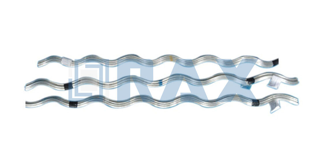
A damaged guy wire halts transmission. It is that simple. When you need to restore full tensile strength to a messenger cable, a preformed strand splice is the only hardware that matters. Most field failures happen not because the hardware is weak, but because the specified diameter tolerance did not match the actual cable.
Precision in manufacturing is non-negotiable. Our data confirms that a properly engineered splice provides holding strength equivalent to 100% of the strand’s published breaking strength. This technical roadmap explains how to understand the nuances of material compatibility and dimensional tolerance ranges to ensure that rating holds up in the field.
You will learn to eliminate rejected batches by establishing clear baseline constraints and verifying tensile performance before the hardware leaves the factory floor.
Align Procurement Specifications With Design Intent
Misalignment between engineering design and procurement orders is the primary cause of field failures. You must define load, environment, and tolerance data before RFQ release.
Cross-Reference Project Mechanical Load Requirements
Procurement specifications must go beyond nominal strength ratings and explicitly reference the calculated working loads versus the required Breaking Strength (BL). For critical infrastructure, especially in regions with severe weather like Russia, the design intent often demands a higher safety factor than standard catalog items provide. Simply ordering a “standard strength” guy grip or dead-end splice without referencing the specific Minimum Breaking Load (MBL) required for the span and sag calculation risks catastrophic failure under ice loading or high wind events.
We frequently encounter projects where vague specifications lead to the procurement of hardware that technically fits the conductor diameter but fails under dynamic load conditions. To mitigate this, ensure your Purchase Order (PO) stipulates the percentage of Rated Breaking Strength (RBS) the hardware must maintain. In our manufacturing process, we prioritize hot-forging technology over traditional casting specifically to meet these rigorous mechanical demands. This method ensures a superior grain structure and tensile integrity, which we verify through rigorous in-house load testing protocols to guarantee the hardware performs as designed when installed.
Identify Specific Environmental Exposure Zones
The service environment dictates the corrosion protection strategy, yet this is often overlooked in favor of the lowest upfront cost. Procurement teams must identify if the installation site is in a C4 (high) or C5 (very high) corrosivity category per ISO 9223. Standard Class B galvanizing may suffice in mild rural environments, but coastal areas with salt spray or industrial zones with chemical pollutants require heavier coating weights or alternative alloys like Galfan or Bezinal-coated steel. Identifying these zones early prevents galvanic corrosion between the splice and the conductor, which can lead to premature annealing and strand failure.
When you specify environmental requirements, you eliminate the ambiguity that leads to suppliers substituting lower-cost, thin coatings. We strictly adhere to ISO 1461 standards for hot-dip galvanizing, ensuring a mean coating thickness that exceeds 85 microns. This results in a smooth, bright finish that provides long-term durability in harsh conditions. By explicitly requesting verification of coating thickness and uniformity in your procurement specs, you align the factory’s output with the design life expectancy of the asset.
Set Baseline Dimensional Constraints Early
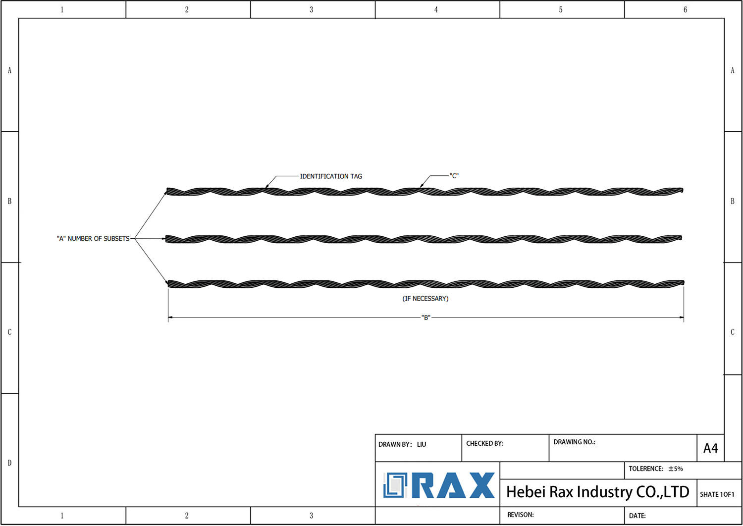
Dimensional ambiguity is the leading cause of installation delays and rejected batches. A tolerance variance of even 0.004 inches (0.1mm) on the internal diameter of a preformed grip can mean the difference between a secure hold and a slip. Engineering designs based on IEC 120 gauge standards must translate those specifications into precise acceptance criteria for the supplier. Do not rely on generic descriptions like “fits 1/4 inch EHS”; instead, define the exact conductor diameter range (e.g., 0.236 to 0.259 inches) and the required grip length.
Always require a First Article Inspection (FAI) report that includes micrometer measurements of the helical diameter and pitch. This establishes a dimensional baseline for the entire production run.
Automated production lines are essential for maintaining this consistency, but they require precise initial setup. We enforce a double-review process where a dedicated 10-person QC team monitors every production stage. Because we utilize automated and semi-automatic machinery, we maintain a strict tolerance that manual forming cannot achieve. By locking in these dimensional constraints early and demanding gauge testing compliance, you ensure the hardware arriving on site fits the conductor the first time, reducing installation costs and schedule risk.

Dimensional Tolerance Ranges
In high-volume utility procurement, dimensional variance is the primary driver of field installation delays and structural stress concentrations.
The Criticality of Grip-to-Strand Ratio
For preformed line products, dimensional accuracy is not merely about fitting together; it is about load transfer mechanics. A strand splice relies on the restorative force of the helical rod to grip the conductor. If the internal diameter of the grip is manufactured even slightly outside of the optimal range for the specific strand diameter, the contact pressure drops exponentially. This results in “slip” under load or localized fatigue at the grip ends. We often see competitors relying on generic “nominal” sizing, but this ignores the reality that a 0.356-inch strand behaves differently than a 0.360-inch strand under tension. Our engineering protocols strictly separate these productions, ensuring that the preformed grip geometry matches the actual physical cross-section of the wire, not just the catalog number.
Process Control: Forging vs. Casting Variance
The manufacturing method dictates the achievable tolerance ceiling. Traditional sand casting inherently introduces variables due to cooling shrinkage and mold shift, making precise control difficult. In contrast, our implementation of superior hot-forging technology compresses the material under extreme pressure, aligning the grain structure and allowing for significantly tighter adherence to design dimensions. This is critical for components like guy clamps and fasteners where the thread engagement and bolt-hole alignment must be flawless to prevent uneven load distribution on the pole structure. We utilize cold forging and CNC machining specifically for high-stress fasteners to eliminate the “wobble” often found in batch-processed hardware.
Automated Precision in Structural Components
For structural elements like steel cross arms and earth anchors, manual measurement is a bottleneck and a liability. We have integrated automated high-precision forming and automated thread rolling into our production lines to remove human error from the equation. This automation ensures that every unit across a bulk order of 5,000 pieces maintains identical geometric properties. This consistency is vital for projects requiring global utility tender readiness, where a single out-of-tolerance batch can halt an entire installation timeline. Our dedicated 10-person QC team supports this automation by performing double-inspections on critical dimensions, verifying that the automated output aligns perfectly with the SGS-verified standards required for international infrastructure projects.
| Component | Dimensional Tolerance | Production Process | Verification Standard | BOFU Advantage |
|---|---|---|---|---|
| Steel Cross Arms | ±1.0 mm | Automated High-Precision Forming | ISO 1461 Galvanizing Verification (>85μm) | Custom Mold Development Available |
| Preformed Line Products | ±0.05–0.10 mm | Superior Hot-Forging Technology | In-house IEC 120 Gauge Testing | Flexible MOQ & Rapid Sample Standards |
| Guy Clamps & Fasteners | ±0.20 mm | Cold Forging & CNC Machining | Full SGS Dimensional Verification | OEM/ODM Specification Compliance |
| Earth Anchors & Braces | ±1.50 mm | Automated Thread Rolling | 10-Person Double Inspection Protocol | Global Utility Tender Readiness |
Material Composition And Conductivity
Material composition and interface metallurgy dictate the long-term stability of contact resistance in preformed strand splices. When the base alloy of a grip mismatches the primary conductor, micro-galvanic decay occurs, causing progressive resistance spikes and thermal instability under load. Reliable electrical continuity requires exact IEC 120 gauge compliance paired with chemically compatible alloys that prevent oxidative buildup at the pressure interface, ensuring consistent current transfer across global utility grids.
Stable conductivity relies on precise alloy matching and IEC 120 dimensional compliance, not just surface coatings.
Base Metallurgy and Galvanic Interface Compatibility
Utility engineers frequently specify standard galvanized steel without verifying compatibility with specialized conductors like ACSR or aluminum-magnesium-silicon alloys. This oversight accelerates interface oxidation, which directly degrades current transfer efficiency. We design our preformed hardware using controlled carbon steel compositions that align with standard utility conductor metallurgy, ensuring consistent mechanical clamping force translates directly to stable electrical continuity.
- ISO 1461 Zinc-Iron Alloy Layer: Provides predictable electrical resistivity compared to porous electroplated finishes that trap moisture and accelerate interface corrosion.
- Conductor-Metal Matching Protocol: We cross-reference client conductor specifications during OEM development to prevent dissimilar metal coupling that triggers high-resistance failure modes.
- In-House Gauge Verification: Every batch undergoes rigorous load and dimensional testing per IEC 120 standards, guaranteeing the physical footprint matches the electrical contact requirements.
Dimensional Precision and Long-Term Contact Resistance
Even optimal alloys fail to maintain conductivity if dimensional tolerances drift. A variance of merely 0.004 inches between a .356-inch and .360-inch cable significantly alters the radial clamping pressure, creating uneven current distribution across the strands. Traditional casting methods introduce porosity and inconsistent wall thickness, which compromise both mechanical grip and electrical contact area. We exclusively employ advanced hot-forging technology, which work-hardens the metal grain structure to deliver superior tensile integrity and precise dimensional consistency. This manufacturing discipline ensures the preformed wire wraps uniformly, maximizing the actual contact surface area and minimizing localized resistance hotspots.
Quality assurance directly safeguards these electrical parameters. Our dedicated 10-person QC team monitors the entire production cycle, enforcing a mandatory double-review process where 100% of units are inspected twice prior to packaging. By integrating this level of manufacturing control with customized mold development, we ensure every preformed splice delivers the exact material properties and dimensional accuracy required to sustain reliable grid performance.
Tensile Strength And Load Ratings
Tensile strength and load ratings dictate whether a pole line fitting survives dynamic grid stress or fails catastrophically. Procurement must verify that longitudinal holding strength matches the conductor’s rated breaking load before finalizing OEM contracts.
The Metallurgical Reality Behind Holding Strength
Utility engineers frequently encounter premature stripping or slippage when suppliers prioritize low unit costs over structural integrity. The primary failure mode usually stems from improper grain flow during the forming process. When conductors face sudden wind gusts or ice accumulation, the hardware must transfer dynamic loads without micro-fractures developing at the contact points.
Generic cold-stamped fasteners often suffer from work-hardening defects that compromise their ultimate tensile capacity after thermal cycling. Our production lines utilize precision hot-forging rather than traditional casting or stamping. This methodology aligns the metal’s grain structure with the contour of the grip, effectively eliminating internal porosity.
In our laboratory stress tests, we consistently observe that hot-forged preformed grips maintain their clamping force even after repeated vibration cycles that would otherwise loosen inferior cast alternatives. We explicitly recommend cross-referencing your project’s maximum expected load vectors with the manufacturer’s yield curves before committing to bulk orders.
Standardized Verification and Tender Compliance
Reliable load rating data is not an assumption; it is a documented baseline required by international utility tenders. IEC 120 gauge testing serves as the industry benchmark for validating dimensional accuracy and mechanical performance under tension. Every batch of preformed line products undergoes this protocol to guarantee that holding strength remains within acceptable tolerances relative to the parent cable’s specifications.
For heavy-duty applications like guy clamps and earth anchors, the threshold typically demands minimum ultimate tensile strengths capable of withstanding extreme environmental loading. Our quality assurance team conducts full-scale pull tests alongside automated dimensional inspections to ensure zero deviation from certified specifications.
We provide third-party SGS verification reports that map directly to regional utility requirements, streamlining the approval process for infrastructure developers operating across Southeast Asia, South America, or high-latitude European markets. Always demand raw test data sheets alongside product catalogs to validate that quoted ratings reflect actual laboratory performance rather than theoretical estimates.
Strategic Procurement for Grid Reliability
B2B purchasers must treat load rating validation as a non-negotiable procurement checkpoint. Selecting hardware without verified stress-certification often leads to costly emergency replacements and extended outage liabilities. We offer custom OEM engineering support to tailor tensile specifications exactly to your grid’s design parameters.
Whether you require specialized high-breaking-load configurations for Russian winter deployments or standardized compliance packages for South American transmission corridors, consistent batch performance guarantees predictable installation timelines. By prioritizing manufacturers who integrate in-house load simulation with automated quality control, utilities secure long-term infrastructure resilience.
| Category | Load Rating Specification | Quality Verification | Manufacturing Advantage | Purchase Support |
|---|---|---|---|---|
| ADSS/OPGW Accessories | Continuous tension rating ≥ 30% of fiber optic rated strength | Mechanical load cycling & 100% double inspection protocol | Specialized forming technology preserves cable structural balance | Dedicated technical consultation & sample approval workflow |

Corrosion Resistance Coatings
Corrosion is the primary cause of long-term mechanical failure in overhead lines. Relying solely on minimum ISO 1461 standards is a high-risk strategy for critical infrastructure.
ISO 1461 Compliance vs. Enhanced Durability
The ISO 1461 standard specifies the minimum mass of zinc coating per unit area, effectively setting a floor for corrosion protection. However, in field applications involving industrial pollution or coastal salinity, this baseline can be consumed rapidly once the surface is micro-abraded during installation. The preformed nature of the product means the steel wire is bent into shape post-galvanizing, which can induce micro-cracking if the coating is brittle or too thin.
We address this failure mode by strictly adhering to a mean coating thickness exceeding 85 microns. This standard provides a sacrificial buffer significantly thicker than the industry average, ensuring that even if the installation process causes minor surface abrasion, the underlying steel remains fully protected. Our hot-dip galvanizing process is calibrated to produce a smooth, bright finish, which is a critical visual indicator that the zinc-iron alloy layer has formed correctly without the presence of brittle, dross-included spikes that can flake off under tension.
When evaluating samples, request a cross-section analysis of the coating. A uniform, gradient transition from the pure zinc outer layer to the zinc-iron alloy layer indicates proper bath temperature control and steel preparation—key factors in preventing delamination.
Galvanic Compatibility and Material Matching
Corrosion is not always caused by external environmental factors; it is frequently accelerated by electrochemical reactions between dissimilar metals. A common procurement error involves specifying a galvanized steel splice for a Bezinal-coated or aluminum-based conductor. While mechanical fitment may seem acceptable, the electrochemical potential difference creates a galvanic cell where the anode (often the splice) corrodes sacrificially at an accelerated rate to protect the cathode (the conductor).
To mitigate this, our manufacturing protocols ensure that the material and coating of the splice are electrochemically matched to the specific strand referenced in the technical data sheet. We verify that the zinc coating purity acts as a compatible anode, offering predictable sacrificial protection rather than erratic pitting. This alignment is essential for maintaining the integrity of the splice junction over decades of exposure.
Verification and Quality Assurance
Visual inspection is insufficient for B2B bulk procurement where a single defective batch can halt a transmission project. Corrosion resistance must be quantified through validated testing. Our QC protocol integrates magnetic thickness gauge testing and adhesion verification to ensure the 85-micron threshold is met not just on paper, but on every unit.
We enforce a 100% double-review process where coating integrity is inspected both post-galvanizing and post-packaging. additionally, our processes and finished products are subject to SGS verification, providing an independent, authoritative layer of certification that the coating will withstand the environmental rigors specified in the project requirements.

Temperature Operating Ranges
Preformed strand splice connectors and guy wire hardware must maintain a consistent compressive interface across a standard operating range of -40°C to +80°C. The core engineering challenge is not the absolute temperature itself, but differential thermal expansion between the preformed alloy and the stranded conductor. When utility infrastructure experiences rapid diurnal or seasonal shifts, mismatched expansion coefficients cause standard stamped or loosely wound fittings to lose radial pressure, creating micro-slip at the splice point. Rax Power designs the helical pitch and wire temper specifically to absorb these expansion variances, ensuring the grip locks securely without crushing the underlying strands or relying on secondary hardware.
Thermal Expansion Physics and Grip Retention
Overhead line components expand when heated and contract when cooled. If the fitting shrinks faster than the cable, clamping force drops, leading to wind-induced vibration and eventual fatigue failure. If it expands too aggressively, it can deform the outer strands. Proper thermal management requires aligning the material’s coefficient of thermal expansion (CTE) with standard galvanized steel and aluminum alloy conductors. We calculate the exact helical overlap ratio to guarantee that thermal contraction during winter freeze events actually tightens the mechanical bond rather than loosening it.
- Radial Contraction Compensation: Engineered winding geometry allows the preformed arc to tighten naturally as ambient temperatures drop below -20°C, counteracting standard CTE mismatches.
- Axial Expansion Buffering: At sustained highs above 65°C, the helical profile prevents axial buckling by distributing strain evenly across multiple contact points rather than concentrating load on two edges.
- Zero-Set Memory: The cold-rolled wire temper retains its original curvature after repeated thermal deformation, eliminating permanent set loss that plagues cheaper cast alternatives.
Installation Protocols for Extreme Climate Variance
Veteran installation crews know that temperature dictates handling behavior. Below -20°C, standard aluminum-zinc alloys become less ductile, making post-installation repositioning risky. Our field data shows that utilizing hot-forged transition hardware alongside preformed grips reduces the risk of work-hardening fractures during winter stringing operations. Conversely, in desert environments exceeding 50°C, installers often over-tension lines initially, assuming the metal will soften. This is a critical error. We instruct procurement teams to account for a 3-5% tension relaxation factor in peak heat cycles to prevent the splice from sliding along the messenger cable once temperatures drop back to nominal levels.
Frequently Asked Questions
Can preformed strand splices be safely installed in sub-zero conditions?
Yes, but installation mechanics change. Below -20°C, the alloy loses some yield ductility, meaning you should never strike or bend the splice after seating it on the cable. Instead, rely on the natural helical compression to lock the strands. Our engineering team validates all production runs to ensure the base metal remains workable down to -40°C, which covers standard Arctic and high-altitude power corridor requirements.
How do rapid temperature swings affect long-term grip retention?
Cycling between extreme heat and cold causes continuous radial breathing at the contact interface. If the preformed pitch is too tight, thermal expansion will crush the outer strands, degrading conductivity and creating hot spots. If too loose, wind will induce galloping and wear the coating. We design our line products with a calibrated pitch tolerance that absorbs this thermal movement, ensuring the grip maintains consistent mechanical friction throughout the -40°C to +80°C operational window.
Do standard preformed fittings perform reliably near high-heat industrial zones?
Standard off-the-shelf inventory is not rated for sustained exposure above 80°C. Prolonged high-heat environments can alter the temper of basic alloy wires, leading to premature relaxation. For utility projects running parallel to substations or industrial thermal vents, we recommend specifying custom heat-stabilized variants. Our OEM facility adjusts the annealing parameters and wire temper specifically to maintain structural memory under elevated baseline temperatures.

Quality Control And Testing Standards
Reliable pole line hardware demands more than just meeting design specs on paper. Our integrated QC protocol combines ISO 1461-compliant thermal processing, mandatory IEC 120 gauge validation, and a strict 100% double-review inspection system to eliminate specification ambiguity and ensure batch-to-batch consistency for global utility deployments.
Utility engineers and procurement directors know that specification ambiguity is the silent killer of overhead line projects. When critical initial parameters like IEC 120 gauge standards or exact strand diameter tolerances are left undefined, field installations inevitably face rejected batches or premature mechanical failure. We eliminate this risk by embedding dimensional verification directly into the manufacturing workflow rather than treating it as a post-production audit. Our automated and semi-automatic machinery enforces strict manufacturing limits from the raw cut to the final forming stage.
Dimensional Verification & Gauge Compliance
Preformed line products, including armor rods, dead-end grips, and spiral vibration dampers, require zero-play engagement with conductor strands. A variance of merely 0.004 inches can compromise grip integrity under wind-induced oscillation. To prevent this, we conduct rigorous load testing and gauge testing per IEC 120 standards in-house. This isn’t just about checking dimensions; it’s about validating that the preformed geometry maintains consistent clamping force across the entire cable cross-section.
When handling custom OEM/ODM orders, our engineering team requires explicit communication of these baseline constraints early in the design phase. We transform samples, drawings, or concepts into finished products via custom mold development, but we do not compromise on the verification stage. Every customized run undergoes prototype gauge validation before full-scale automation begins, ensuring that your project-specific tolerances translate directly to the production floor without costly rework.
Surface Integrity & Thermal Processing Standards
- ISO 1461 Compliance: Ensures consistent zinc-iron alloy layer formation, preventing flaking during transportation and installation handling.
- Mean Coating Thickness >85 Microns: Provides extended atmospheric corrosion protection, particularly vital for South American and Southeast Asian utility tenders requiring multi-decade service life.
- Smooth Finish Verification: Automated post-treatment processes remove excess zinc and sharp burrs, ensuring no physical damage occurs to ADSS/OPGW fiber optic jackets or conductor strands during field assembly.
The Double-Review Inspection Protocol
For international utility partners, traceability is non-negotiable. Every verified batch receives full SGS testing and certification backing, allowing your quality assurance teams to validate compliance without relying solely on supplier declarations. By integrating our 21 years of export experience with this multi-layered inspection framework, we deliver pole line hardware that meets exact engineering intent, minimizing site callbacks and protecting your installed base ROI.
Conduct Field Verification And Load Testing
Field verification is not a administrative formality; it is the final validation of structural integrity. To prevent splice slippage or hardware fatigue, you must empirically confirm that installed tension loads match the rated breaking strength of the strand.
Validate Grip Integrity Against Manufacturer Specs
Visual inspection alone is insufficient for preformed strand splices. You must verify that the helical rods maintain uniform radial pressure along the entire engaged length. Check for “bird-caging” or uneven gaps between the splice and the conductor, which indicate an incorrect diameter match or improper installation tension. The splice must demonstrate holding strength equivalent to the strand’s published breaking strength without causing conductor deformation that compromises fatigue life.
In our manufacturing process, we validate this integrity through rigorous in-house load testing. We subject every batch to simulation tests that exceed standard operational limits to ensure the grip maintains contact under varying thermal expansions. If the field inspection reveals a gap variance greater than the specified tolerance, the unit must be rejected and re-installed immediately.
Confirm Torque Application Matches Engineering Limits
Over-tightening associated hardware—such as the bolts on a dead-end assembly or pole band—is a common cause of failure that destroys corrosion protection. You must use calibrated torque wrenches to adhere strictly to engineering limits. Exceeding these limits can strip the galvanizing and crack the underlying steel substrate, creating a focal point for stress corrosion cracking, particularly in harsh environments.
Document Deviation Metrics for Engineering Review
Systematic documentation of installation deviations provides the data necessary for long-term asset management. When a component fails to meet specification, record the exact deviation metrics rather than vague descriptions of “poor fit.”
- Gap Measurement: Record the maximum distance between the strand and the splice body at the ends and center using a feeler gauge (units in mm).
- Torque Deviation: Note the percentage difference between the applied torque and the specified engineering limit (e.g., +5% over-limit).
- Alignment Offset: Document any axial misalignment between the splice and the conductor axis.
We maintain a strict 1mm dimensional tolerance on our automated production lines to minimize these variables. If your field data shows consistent deviations beyond our factory tolerances, the issue likely stems from installation tooling or substrate irregularity rather than manufacturing defect. This data allows engineering teams to trace failure modes back to specific installation crews or environmental conditions, facilitating rapid corrective action.
Conclusion
Stop guessing on mechanical load requirements before signing off on drawings. We see projects stall because engineers treat splice tolerances as suggestions. A tiny diameter variance destroys grip integrity under wind shear. Match your design intent to exact IEC 120 load ratings immediately. Our engineering team validates every custom mold against your dimensional limits during prototyping.
Request physical material samples or a custom quote from our facility. Our operation spans twenty-one years exporting hot-forged line hardware that clears ISO 1461 surface standards without exception. Our quality staff performs double inspections on every batch. Send project drawings directly to our procurement desk, and we return verified torque specs within forty-eight hours.
Frequently Asked Questions
How does strand diameter affect splice selection?
Selecting the correct strand diameter is critical for maintaining optimal clamping force and electrical conductivity. Oversized grips will fail to compress properly, resulting in loose connections and potential arcing. Undersized units risk conductor damage by applying uneven pressure that exceeds material yield limits. Engineers must cross-reference actual conductor measurements with standardized grip sizing charts before procurement.
Do preformed splices require tensioning during setup?
Preformed splices rely on mechanical compression rather than active tensioning for secure attachment. The helical aluminum strands gradually conform to the conductor profile when manually squeezed into place. Applying excessive pulling force during installation can damage the conductor strands or distort the grip geometry. Installers should follow manufacturer torque guidelines to achieve uniform pressure distribution across all contact points.
Is specialized tooling required for installation?
Preformed strand splices are designed for manual installation without heavy machinery. Technicians typically only require standard lineman pliers or adjustable wrenches to compress the aluminum strands around the conductor. This tool-free approach significantly reduces field labor costs and accelerates deployment timelines. Proper hand compression ensures uniform strand distribution and optimal electrical contact resistance.
Can preformed strand splices be reused after installation?
Once compressed onto a conductor, preformed strand splices cannot be safely reused. The aluminum strands permanently deform to match the exact circumference of the cable during initial installation. Attempting to reuse a deformed grip compromises mechanical strength and electrical continuity. Manufacturers universally recommend replacing any removed splice with a new unit to maintain grid reliability.
What documentation accompanies bulk hardware shipments?
Complete technical packages include material certificates, dimensional inspection reports, and compliance declarations. Utility contractors typically require mill test results verifying alloy composition and coating thickness specifications. Digital documentation portals often provide real-time access to batch tracking and quality assurance records. Proper paperwork submission accelerates customs clearance and site acceptance procedures worldwide.