
Picture the rebuilt crossarm at the top of the morning’s work order. New pins sit in the truck box beside a carton of polymer pin insulators, every thread packed with factory mastic. The job looks like simple threading, yet the sequence decides whether the unit stays tight for years or works loose within a season.
Crossarm pins and pin insulators ship on the same export orders, and the pairing questions reach the RaxPower order desk before crews install polymer pin insulator units in the field. Which thread does the insulator expect, what stops the tightening, and what keeps the conductor seated in the groove. Those three questions are the steps below.
What a Polymer Pin Installation Actually Involves
A pin insulator carries the conductor load in cantilever, from the tie at the groove, through the housing, into the pin and the crossarm. The anatomy and the load path belong to this what is a pin insulator explainer, so they stay brief here. What concerns a crew on the pole is the interface chain: pin thread, insulator thread, mastic, hardware, and tie.
Choosing the unit itself is a separate discipline of voltage, creepage, and cantilever ratings, covered in this composite pin insulator engineering guide. This page stays on the hands-on sequence. Read the five steps in order, because each one protects the interface the next one builds.
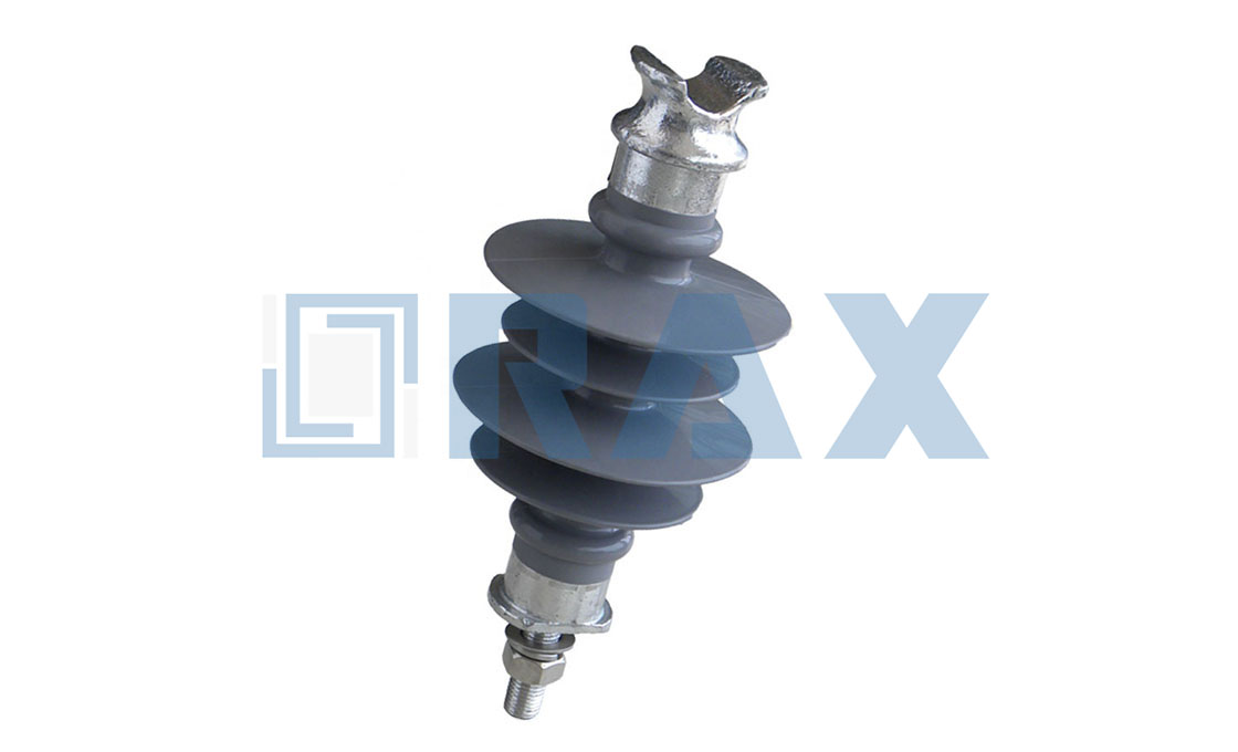
One caution sets polymer apart from its porcelain ancestors. The housing is a rubber jacket over a fiberglass core, so the tightening discipline lives in the thread interface, never in leaning on the shed with a wrench. Every rule below follows from that single material fact.
The staging list comes together on the tailgate. The insulator, a spare pin of the correct thread, a file for dressing thread nicks, the wrench that fits the pin hardware, and the ties travel up in one trip. One missing item turns a pole-top visit into a second climb, and nobody thanks the truck for that.
Step 1: Check the Pin and Thread Seat
Crews who install polymer pin insulator hardware start on the ground, not at height. Confirm the pin is straight, fully threaded, and standing square to the arm, because a bent pin loads the housing sideways from day one. Dress light nicks out of the threads with a file, and reject any pin with crushed or flattened thread crests.
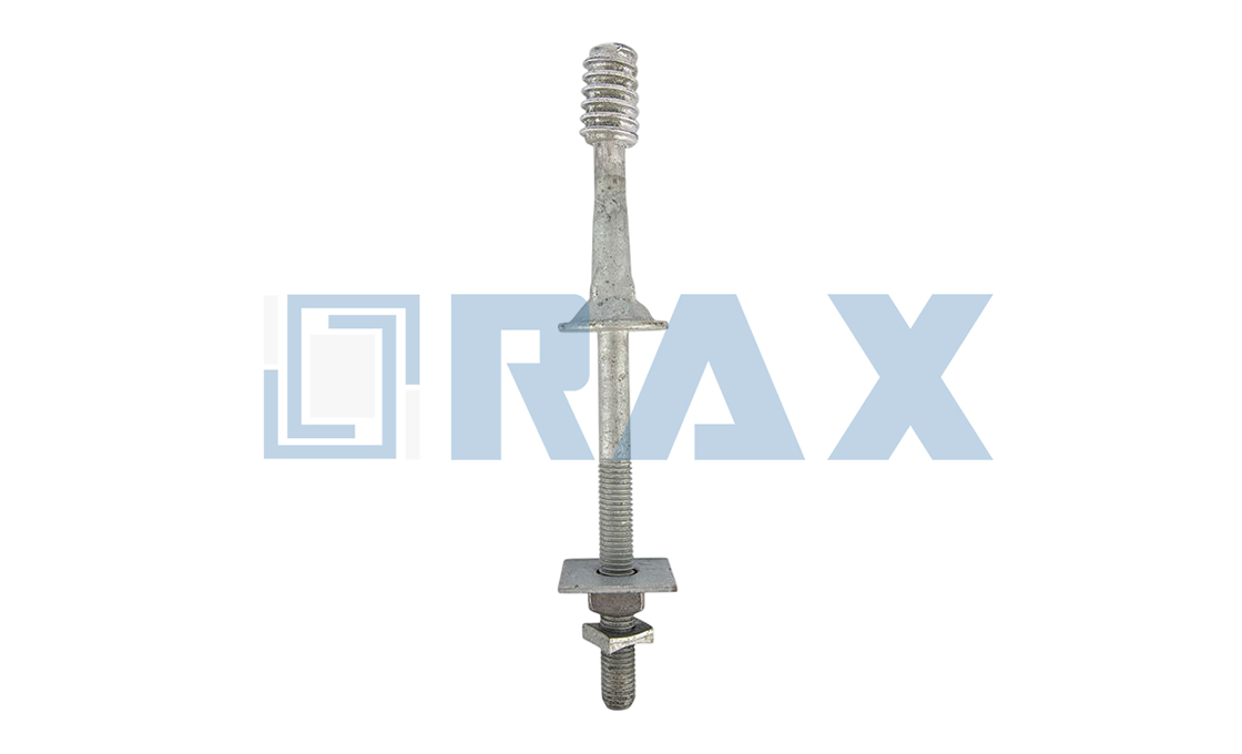
Thread matching is the heart of the check. The pin data worth working from names two standards to meet. Forged steel pins come with molded nylon alloy or cast lead threads, in 1-inch or 1-3/8-inch ANSI sizes, hot-dip galvanized per ASTM A-153. Published polymer pin insulators mount on the same two pin diameters. The published tie-top line states it plainly: 1-inch or 1-3/8-inch pins. Its head and neck dimensions match ANSI C29.5 and C29.6 porcelain designs.
Run the check as a short sheet rather than from memory.
| Check Item | What Passes |
|---|---|
| Pin thread size | 1-inch or 1-3/8-inch ANSI/NEMA thread, matching the insulator bore |
| Thread material | Molded nylon alloy or cast lead, undamaged over the full engagement length |
| Shank and height | Short or long shank chosen for the arm build and the clearance |
| Coating | Hot-dip galvanizing intact, per ASTM A-153 |
| Insulator bore | Factory mastic present, no cracked sheds at the base |
A mismatch found here costs a truck trip. The same mismatch found at height costs a return visit with the arm already rigged. Ten minutes of ground work buys the whole job.
Step 2: Hand Tighten Until the Mastic Resists
Start the insulator square onto the pin, the way you would start a jar lid, because crossed threads never recover at height. Hand pressure is the specified tool for this step, and the factory compound is the specified gauge.
“Install the insulator on the pin and hand tighten until the mastic material provides resistance to the installation rotation.” — polymer tie-top insulator installation procedure, Step 1
The mastic in a new insulator thread is not packing residue. It is the designed interface, and the firm, even drag you feel as it engages tells you the thread is seating without crossing. Run the housing in with gloved hands until that drag says the stop is reached, and leave the wrench in the truck.
Crews sometimes ask whether hand force really holds. The engagement length of a full ANSI thread, seated against factory compound, is what the design counts on for service. Forcing it tighter adds nothing except risk to the housing.
The reuse rule on the same sheet draws the line cleanly for vise-top bodies. VT polymer insulators may be reused if they are in good condition, while their torque bolts may not. That asymmetry tells a crew where the wear actually lands: in the hardware that makes the joint, not in the housing that guides it.
Step 3: Align the Groove With the Conductor
The tie groove must sit in line with the run of the conductor. Published procedure allows up to an additional one half turn past the mastic stop for exactly this alignment, and no more.
If the half-turn is spent and the groove still misses, the fix lives in the pin, not the housing. Loosen the nut on the pin, rotate the whole insulator until the groove lines up, and retighten the hardware. The same guidance adds one condition worth keeping in view: the insulator must remain tight on the pin and in contact with the mastic.
Backing a seated unit off to hunt for the groove destroys that contact. The half-turn allowance exists so the stop and the alignment can both be true. That is how a crew can install polymer pin insulator units on an arm built around old porcelain pin sizes without guessing at either one.
Which groove takes the conductor is written into the construction standard for the position, top groove on tangent builds and side groove where the line turns. The ANSI head carries both profiles, and the tie that fits the neck size confirmed in Step 1 is the tie that seats without forcing.
Step 4: Tighten the Hardware to Its Stop
The wrench belongs to the pin hardware, never to the housing. Where the construction uses a double-arm pin or a bracket stud, the nut and washer under the arm carry that duty. They take the torque value the construction standard calls for. Write the documented figure on the work order, because a feel-based guess is not a value anyone can audit later. That paperwork habit matters doubly on jobs where crews install polymer pin insulator units beside existing porcelain, because the two tightening stops differ.

Vise-top polymer insulators move the torque limit into the hardware itself. Their nylon torque bolts tighten until a reaction ring shears off flush with the hex head, bottom bolts first, then the top. The broken ring is the torque record, readable by anyone who looks up at the pole.
“Secure the conductor in the VT insulator by first tightening the BOTTOM torque bolts until the ring breaks off flush with the hexagonal head of the bolt. Next, tighten the TOP torque bolt in the same manner.” — vise-top polymer insulator procedure, Step 4
The same sheet carries a warning worth repeating to every new hand. Torque bolts that have already snapped never go back in, and any bolt that has been loosened for any reason is replaced with a new one. In our experience, the crews who carry a bag of spare torque bolts are the ones who never improvise with a used one.
A stop that never arrives is its own finding. If the pin nut keeps turning without the reading climbing, the thread is already damaged, and the honest fix is a new pin rather than a deeper wrench. The same rule protects vise-top hardware: a torque bolt that spins without shearing has failed, and it comes out, not back in.
Shed Orientation and Spacing on the Crossarm
A pin insulator works shed-down, umbrella fashion, so rain and washing water leave the housing without creeping along the skirt. Mount the unit upright on a vertical pin and the geometry takes care of itself. A unit set off angle defeats the shed shape it was molded with, however tight its thread may be.
Pole-top pins extend the same rule above the arm. Units mounted on vertical pins at the pole top follow the identical upright discipline, and they deserve the identical ground-check treatment, because nothing about height relaxes the geometry. Where the design steps up to post or suspension hardware, that assembly has a procedure of its own, and this page does not reach it.
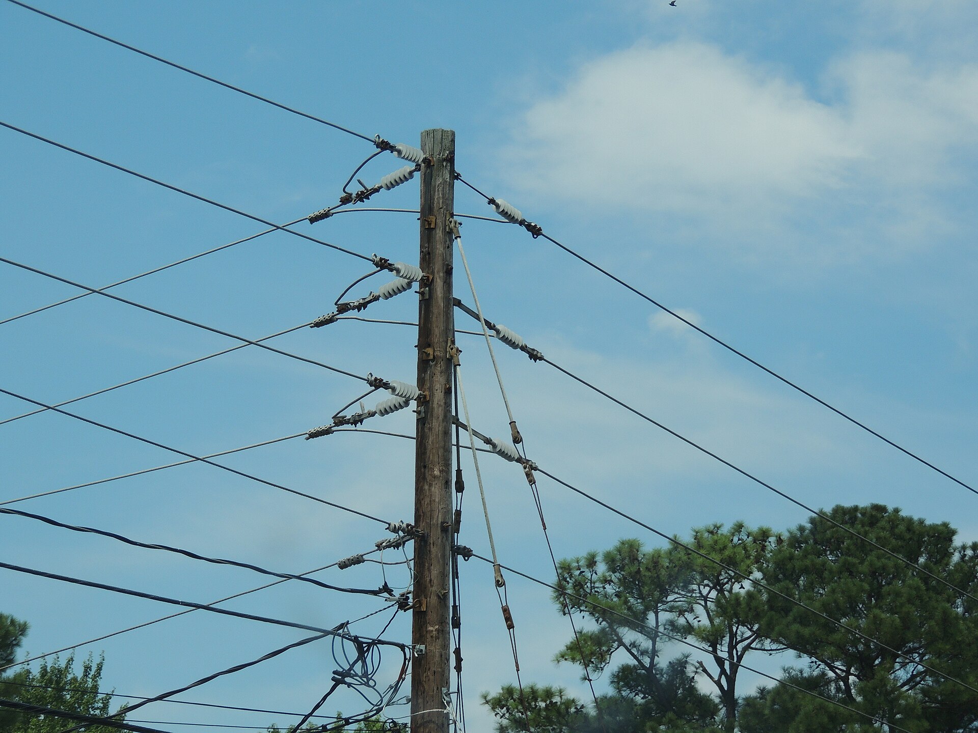
Spacing is the second quiet discipline. When the arm carries three phases on separate pins, each unit gets the same seating and alignment routine, because one loose insulator hands its load to its neighbors. Keep the clearances in the line design’s own sheets, and let the housing, not the hardware, own the air between phases.
The in-service half of the bargain starts the day the tie goes on. Tie wear, neck checks, and the re-tie or replace decision belong to this pin insulator support hardware maintenance guide, and they pick up where this procedure stops.
Step 5: Tie the Conductor and Close Out the Job
With the unit seated, aligned, and tight, the conductor goes into the top groove or the side groove per the design, and the tie closes the mechanical loop. Formed wire ties drop straight onto ANSI-profile heads, which is the point of the standardized neck dimensions in the first place. Hand ties follow the same geometry when formed ties are not on the truck.
The Close-Out Record
Acceptance is a short list run twice, once by the crew and once by the record. Walk it from the ground after the tools are stowed.
- Thread engagement is full, with the mastic stop reached and the half-turn allowance spent on alignment only.
- The groove runs parallel to the conductor, with no sideways lean in the housing.
- Pin hardware sits at its documented value, or every vise-top ring rests broken off flush.
- The tie is complete, with ends dressed and no bare strand working out of the groove.
- A photo and a note put the pole, the pin size, and the date into the job record.
Records like this earn their keep later. A pole number and a pin size turn next season’s question into a lookup. The photo settles what the arm looked like before the weather had its say.
By the time the bucket comes down, the whole job should read as one chain: the ground check, the mastic stop, the half-turn, the hardware, and the tie. RaxPower packs crossarm pins and pin insulators for exactly that chain, in matched ANSI sizes. The last discipline when crews install polymer pin insulator assemblies is therefore the same as the first. Nothing on the pole was left to feel.
Frequently Asked Questions
Do polymer pin insulators need a torque wrench?
Tie-top designs do not. The specified stop is hand pressure against the factory mastic, plus at most a half-turn for groove alignment. Vise-top designs replace wrench settings with break-off torque bolts, tightened until the ring shears flush.
Why is the thread of a new insulator full of mastic?
It is the designed interface, not packing residue. The resistance you feel at hand tight is the stop the procedure counts on, and the seated unit must stay in contact with that mastic.
What pin thread does a polymer pin insulator expect?
Published designs mount on 1-inch or 1-3/8-inch ANSI thread pins, with C, F, or J neck profiles for the tie. Confirm the pin size on the ground, before the climb.
Can the insulator be backed off to line up the groove?
Only within the published half-turn allowance. If the groove still misses the conductor, loosen the nut on the pin, align the whole insulator, and retighten instead of forcing the housing back.
How tight is a vise-top insulator supposed to get?
Tighten the bottom torque bolts until the reaction ring breaks off flush with the hex head, then the top bolt the same way. Never reinstall torque bolts that have already snapped.