
Our order desk still receives inquiries that say "pin insulator" on the drawing and "spindle insulator" in the same notes. One product carries two names, and rarely a short definition. Buyers from distribution utilities and buyers from railway or telecom backgrounds often mean the same hardware while describing it in different words.
This article settles the term once. It defines the term and walks through each part of its anatomy: the body, the sheds, the groove, and the threaded seat. It then explains the steel pin beneath the body and marks the voltage range where this design is the right answer.
What the Name Pin Insulator Actually Means
A pin insulator is the porcelain, glass, or polymer body that screws onto a separate steel pin to carry a single conductor on an overhead line. The American National Standard test-methods document ANSI C29.1 captures the mechanical idea in one clause, calling it "an insulator having means for rigid mounting on a separable pin". Every other feature of the design flows from that arrangement: a rigid insulating body, a separable metal pin, and a structure to hold both.
In field vocabulary the word can refer to three different things. It may mean the insulating body alone, the steel pin alone, or the pair assembled together. Suppliers catalog the steel fitting as an "insulator pin" or "crossarm pin", so a specification saying "pin insulator" almost always means the body. TTF Power's technical overview describes the assembled role plainly, defining it as "a type of electrical insulator used in overhead power line construction to support and separate conductors".
One boundary matters before anything else. The assembly supports one conductor at one phase position. It is not a strain assembly. The conductor stays supported in near-vertical loading, and any line angle or dead-end force beyond a few degrees moves the design toward suspension or strain hardware.
Anatomy of a Pin Insulator, Part by Part
Picture the body turned upside down on a bench, the way a storeroom keeper receives it. From top to bottom you find the same four features on nearly every design. There is a conductor groove, one or more weather sheds, a side groove on tie-top variants, and a threaded or cemented seat that grips the steel pin.
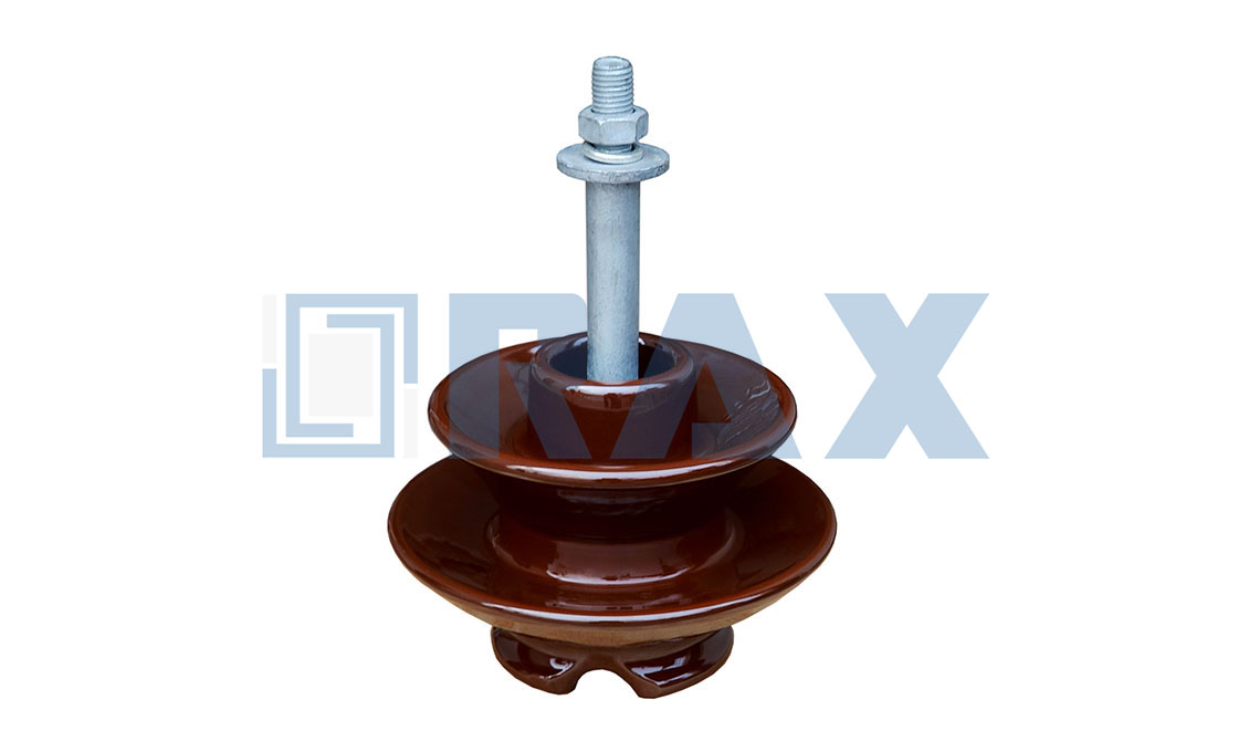
The top groove is the saddle where the conductor rests. The sheds, also called skirts or petticoats, are the umbrella-shaped flanges that extend the leakage path down the outside of the body. SUNJ Electric's overview puts their function in one line, noting that these bodies "are made with several skirts to increase surface area and creepage length". More sheds mean a longer leakage path and steadier behavior in rain and pollution.
The threaded seat inside the skirt is where the separable pin enters. On porcelain bodies this cavity is usually cemented to a galvanized steel thimble that carries a standardized lead thread. The body therefore never threads directly against bare steel. The way you thread a mason's anchor into a wall plug is a fair analogy. The soft, standardized interface takes the wear so the strong parts behind it do not.
History explains why porcelain took the lead. Wet-process ceramic bodies were the first mass-produced insulation for overhead lines, and the manufacturing route is well understood on every continent. Kaolin, quartz, and feldspar fire into a dense, glazed shell that ignores sunlight, resists surface tracking, and holds its threads for decades. Glass followed as a rival body material, and polymer arrived last with a weight and vandalism story of its own.
The Steel Pin That Does the Real Holding
The insulator body gets the name on the drawing, but the steel pin under it carries the working load. TTF Power notes the assembly "mounts directly on a pole using a metal pin". In practice that pin is a hot-dip galvanized steel or malleable iron fitting with three defining features.
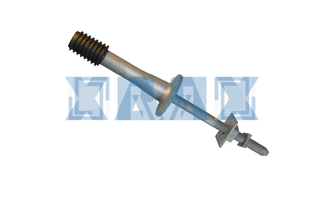
The first feature is a lead-thread head that the insulator screws onto. The second is a shoulder that seats the body at the correct working angle. The third is a square or tapered shank that bolts into the cross-arm.
This division of labor explains the whole concept. The porcelain or polymer body handles the electrical duty, standing the line voltage off from the grounded arm. The steel pin handles the mechanical duty of conductor weight, wind, and ice, and passes those loads into the cross-arm. Because the two parts separate, a cracked body can be replaced without changing the pin, and a bent pin can be swapped without touching a sound insulator.
The pin itself is a small catalog of variants once you look closer. Shank lengths differ so the body clears the arm flange by the right distance. Square shanks grip round bolt holes on wood arms, while tapered fittings seat into ironwork. Some heads take a solid cemented body, others carry a replaceable thimble thread. None of this shows in the product name, which is why the drawing and the packing list both need a second look before an order is placed.
How the Conductor Sits on the Top Groove
The conductor is not bolted to the body; it is tied. TTF Power describes the standard practice, in which the conductor "clamps onto the top groove of the insulator" and is secured with binding wire. A soft aluminum or copper tie wire wraps the conductor into the groove in practiced patterns. Linemen speak of "top ties", "side ties", and "tie-top" designs as a small discipline of their own.
The tie is a deliberate wear part. It flexes with conductor wind motion for decades, so utilities inspect ties on regular patrol rounds instead of waiting for a failure. Reading tie-wire wear, neck checks, and the meaning of a leaning unit are maintenance topics. We treat them separately in the support hardware upkeep guide. The anatomy point here is simpler: the groove-and-tie interface is a designed friction joint, not an afterthought.
Tie patterns deserve a line of respect as well. A top tie locks the conductor against uplift on open spans, while a side tie holds it against a direction the wind favors. The patterns are simple once learned but unforgiving when improvised. Most utilities limit crews to two or three standard wraps across the network, so any lineman can read any pole.
Porcelain, Glass and Polymer Body Materials
Three body materials cover nearly every unit sold today. Each one changes the maintenance story more than the electrical story. The table below lines them up against the features a buyer actually weighs.
| Body material | What it is made of | Field character |
|---|---|---|
| Wet-process porcelain | Kaolin, quartz, and feldspar, glazed after firing | The long-service default; rigid, heavy, unaffected by UV |
| Toughened glass | Annealed, heat-treated glass | Damage shows visibly; shells shatter on failure instead of hiding it |
| Polymer (composite) | Silicone rubber housing over a fiberglass core | Light to handle; hydrophobic surface sheds water in wet service |
PGC's materials comparison highlights the glass advantage exactly as linemen use it, praising a transparency "which facilitates easy inspection for internal damage". For polymer, the same source describes a housing of "silicone rubber molded over a fiberglass core". It adds that composites "excel in wet conditions thanks to their hydrophobic properties". Porcelain remains the volume choice for distribution work because its glaze sheds water predictably and its rigidity suits the pin-and-groove arrangement.
Material choice also sets the purchasing checklist. Porcelain bodies are audited through porosity and thermal-shock tests, polymer bodies through housing tracking and core tests. Each path has its own factory-QC sourcing tests. The polymer branch of the family sits close to the composite longrod covered in the complete polymer insulator guide, with the pin seat adapted for direct cross-arm mounting.
Which body suits which buyer comes down to service priority. A utility stocking one spare for mixed feeders usually standardizes on porcelain for its predictable glaze behavior and long shelf life. A buyer in a high-vandalism corridor often moves to polymer because a lightweight composite unit has little scrap value and survives handling drops that would crack a shell. Glass suits owners who want failures to announce themselves: a shattered shell is visible from the ground on the next patrol.
Why the Pin Design Rarely Goes Above 33 kV
This design is a distribution-class workhorse, and its voltage ceiling comes from geometry rather than materials. The whole line-to-ground voltage stands across one body mounted on one rigid pin. Every voltage step upward demands a longer, wider body, and the cantilever load on the pin grows with it.
The traditional porcelain ladder runs in one-piece, two-piece, and three-piece builds. TTF Power's construction overview gives the classic bands. Single-piece designs serve systems up to 11 kV, two-piece designs handle up to 22 kV, and three-piece designs are ideal for 33 kV systems. Above that level the body grows heavy and costly enough that the pin arrangement loses to alternatives. MacLean Power Systems catalogs its pin-class polymeric units for "distribution class applications at voltages below 35kV", the same boundary stated as a product range.
| Line voltage class | Typical build | Shed count, porcelain |
|---|---|---|
| Low voltage / to 11 kV | One-piece body on a single pin | 1–2 sheds |
| 11–22 kV | Two-piece body, cemented stack | 2–3 sheds |
| 22–33 kV | Three-piece body, or polymer equivalent | 3+ sheds |
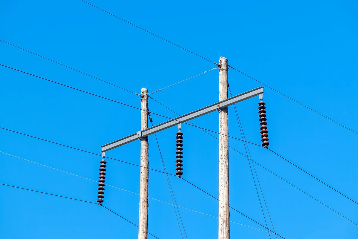
| Above 33 kV | Suspension strings or line posts take over | Not economical as pin type |
Within the pin family's own range, the selection questions decide which unit fits. Creepage for pollution zones, cantilever strength, and thread style top that list. Those sizing questions are engineering-guide territory. They are covered line by line in the composite selection guide and the companion piece on choosing the right composite unit.
Where a Pin Insulator Mounts on the Pole
In service, position tells you the job. The pin bolts vertically into a wood or steel cross-arm, the body screws onto the pin, and the tied conductor runs past the arm at its phase position. Distribution poles commonly carry two arms, so a single structure holds six phase positions, each on its own insulator.
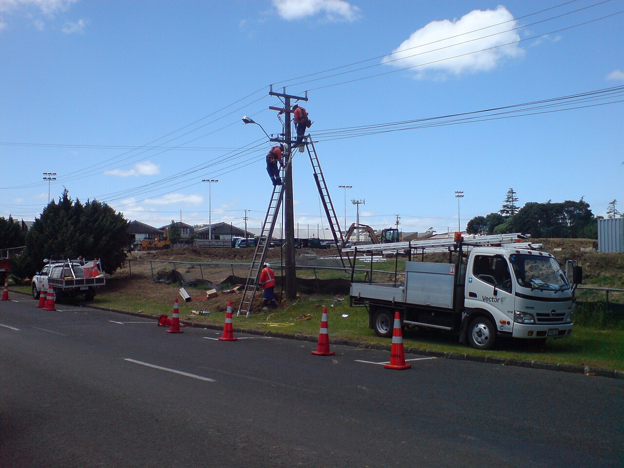
The cross-arm mounting separates a pin insulator from its nearest neighbors. A cross-arm insulator is the broader category: any insulator standing at the arm position, including posts and spools. The arm-attachment mechanics are explained in the cross-arm insulator explainer. A pin insulator is one specific answer at that position, with a body plus separable pin and a tied conductor on top. A line post, by contrast, bolts directly to the arm without a separable pin and leans on its own cantilever strength instead.
The mounting position also dictates the failure view. The body sits upright with the conductor tied above it. Flashover damage therefore marks the skirts from the tie wire downward, and mechanical failures show first as a lean. That lean is the visible symptom which sends crews back to check the pin, the seat, and the tie, in that order.
Clearances close the checklist. The tied conductor must keep its regulated distance from the arm, from the pole, and from neighboring phases through wind swing, and the body height is what buys that distance. Crews therefore treat the body as a dimensioned component, not a generic fitting. Any substitution goes back through the line drawings rather than being judged by eye at the pole.
Sourcing a Pin Insulator That Fits Your Line
Defining the term is step one — matching the body, pin, and thread to your line voltage is step two.

Between definition and purchase sit the practical gates. These are factory compliance paperwork, mechanical and electrical test reports, and galvanizing verification on the pin side. Buyers who need a defensible incoming-quality process can start from the five factory QC sourcing tests run on these units before shipment. The anatomy above then folds directly into their own receiving checks.
Frequently Asked Questions
What is a pin insulator in simple terms?
An insulating body, usually porcelain or polymer, that screws onto a separate steel pin on the cross-arm and carries one tied conductor, generally on lines up to 33 kV.
What is the difference between the insulator and the pin?
The insulator is the porcelain, glass, or polymer body that handles the electrical duty. The pin, also called a spindle, is the galvanized steel fitting beneath it that carries the mechanical load into the cross-arm.
How is the conductor fixed to the insulator?
It rests in the top groove and is secured with binding wire tied in standard patterns. Top ties and side ties are chosen per line position, and the tie is treated as a renewable wear part.
Why are sheds added to the insulator body?
Sheds extend the leakage path along the outside surface, increasing creepage distance. More sheds improve performance in rain and pollution by keeping part of the surface dry and protected.
What voltage can this insulator handle?
Conventional designs serve systems up to 33 kV: one-piece bodies to about 11 kV, two-piece to 22 kV, three-piece to 33 kV. Above that, suspension strings and line posts take over.