
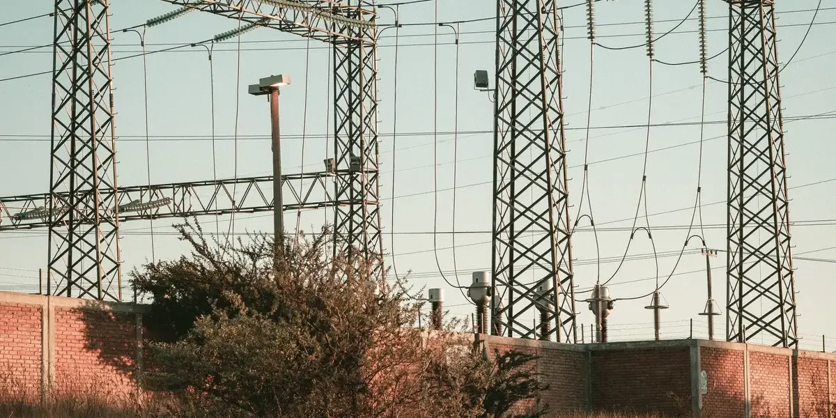
Scaling utility infrastructure usually means fighting concrete cure times and soil variability, which wrecks grid rollout schedules. A ground screw foundation offers immediate load capacity and zero cure time, but the engineering requirements differ vastly between a fixed-tilt solar array and a high-voltage transmission tower. You cannot swap specs between these projects and expect the same result.
Solar arrays prioritize wind uplift resistance and speed, while transmission towers demand deep, high-torque anchors to handle massive static loads. While solar farms often rely on smaller diameters for rapid deployment, utility-grade transmission structures require the increased bearing capacity of shafts up to 139.7mm to ensure stability over decades. We analyze how soil testing protocols diverge and why installation machinery costs vary significantly across these terrains.
Misapplying solar-grade specs to transmission corridors invites anchor failure, yet over-engineering solar farms with transmission-grade steel destroys your unit economics. Understanding these technical distinctions protects your project from non-compliance and keeps your total installed cost on target.
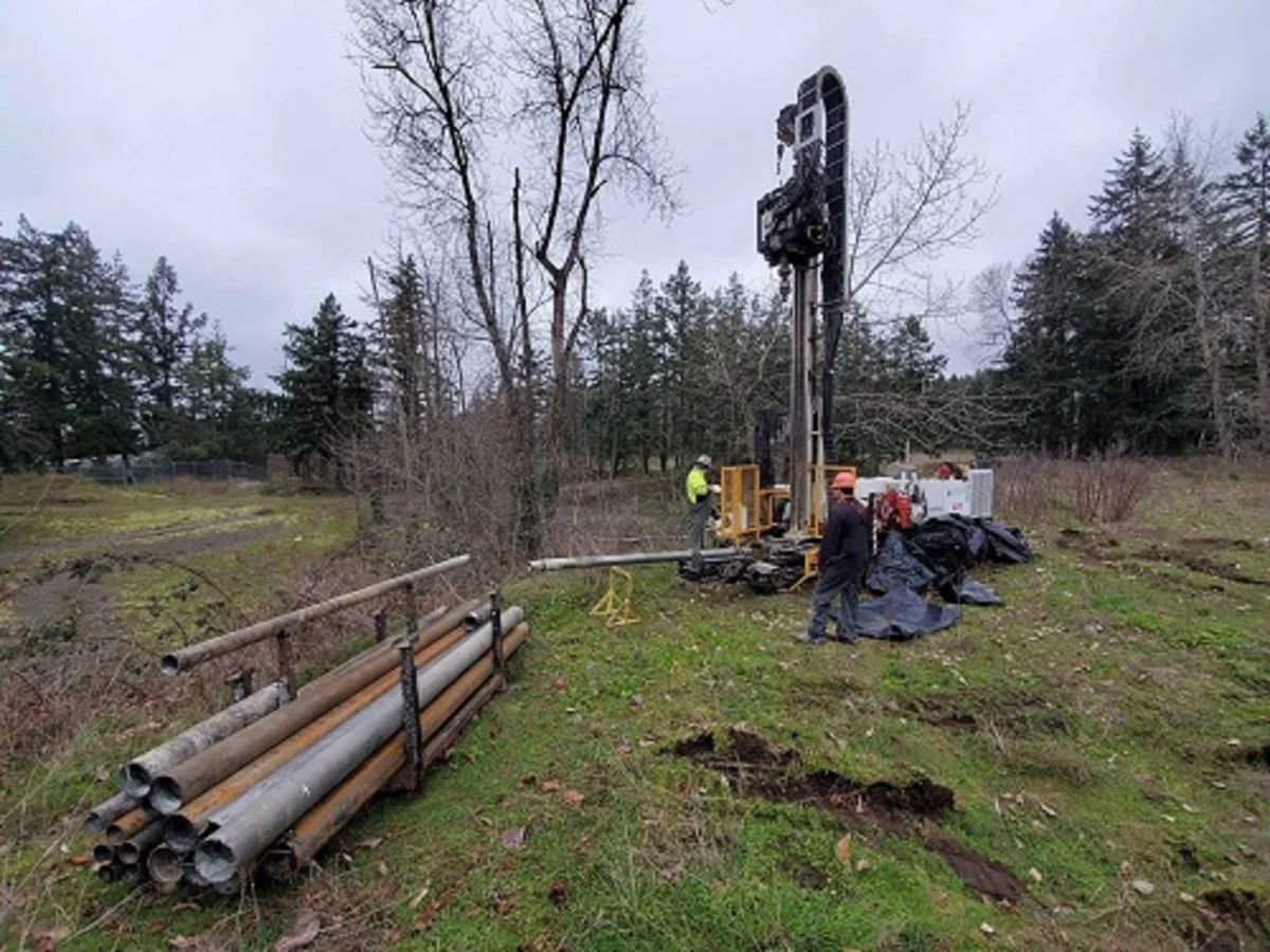
How Ground Factors Drive Screw Choice
Soil density, required installation torque, and anticipated environmental loads dictate helix geometry, shaft forging methods, and galvanizing specifications before a single anchor is driven.
Selecting the correct ground screw foundation is not a generic catalog exercise. The soil profile determines whether a single large helix, a multi-plate configuration, or a no-wrench expanding anchor is appropriate. The operational load profile dictates shaft integrity and torque tolerance. The environmental exposure sets the galvanizing standard required to meet the project lifespan. Mismatching any of these factors leads to installation refusal, shaft fatigue, or premature corrosion failure.
Soil Density Impact on Helix Configuration
In dense, compacted soils, a smaller pitch and robust single-plate helix drive efficiently without over-stressing the installation rig. Loose, silty, or variable strata require multi-helix arrangements that distribute bearing load across a wider soil volume, or engineered extension rods that bypass unstable topsoil to reach competent bearing layers. The helix diameter and plate spacing must be calculated against the actual geotechnical report, not assumed from regional averages.
- High-density clay or gravel: Single large-diameter helix with aggressive pitch reduces installation time while maintaining holding strength.
- Silty or loose sandy substrates: Multi-plate helical configurations increase surface area engagement, preventing premature settlement under cyclic loading.
- Unstable upper layers: Custom extension rods allow the active helix to reach designated depth without altering the foundation head elevation.
Our engineering team sizes these configurations using in-house IEC 120 load testing and SGS-verified pull-out data, ensuring the selected helix geometry matches the actual soil mechanics rather than generic assumptions. We validate holding strength through rigorous gauge testing and load cycles before authorizing production runs.
High-Torque Requirements for Transmission Anchors
Transmission guy wires and tower foundations subject anchors to extreme lateral and tensile forces during commissioning and field operation. The driving torque required to install these units must not compromise shaft integrity. Traditional cast steel components can harbor micro-porosity that fails under peak torque loads, making hot-forged shafts the baseline for utility-grade transmission anchors.
We specify hot-forged manufacturing for our helical and no-wrench screw anchors because it aligns the grain structure of the steel with the shaft axis, delivering superior tensile strength compared to casting methods. Every batch undergoes a double-review inspection protocol where 100% of products are checked twice before packaging, eliminating defective units from reaching the site. This level of scrutiny is non-negotiable for projects operating in extreme environments, such as the high-breaking load requirements typical of Russian utility corridors.
- Shaft integrity: Hot-forged round and square shafts withstand high installation torque without risk of torsional failure.
- Corrosion specification: Hot-dip galvanizing compliant with ISO 1461 and ASTM A153 Class C provides a mean coating thickness exceeding 85 microns, protecting against aggressive soil chemistry over a 50-year tower service life.
- Load validation: Rigorous in-house load testing per IEC 120 confirms that holding capacity meets design margins before shipment.
Wind Uplift Resistance for Solar Arrays
Utility-scale solar arrays generate significant upward lift forces during high-wind events, particularly in open terrain or areas prone to storm surges. The ground screw choice must prioritize pull-out resistance over pure driving efficiency, which shifts the focus toward helix diameter, plate spacing, and soil engagement depth. Solar-specific foundations are engineered to handle cyclic wind loading without progressive soil degradation around the helix.
For solar farm applications, we design helical anchors and ground screw foundations to maximize uplift capacity while maintaining compatibility with powered installation rigs used across large-acreage sites. Custom mold development allows us to adjust flange geometry and helix profiles to match specific wind load calculations provided by EPC contractors. Automated production ensures dimensional consistency across high-volume orders, meaning every anchor in a multi-hectare array performs identically under operational stress.
- Uplift optimization: Larger helix diameters and optimized pitch angles engage more soil volume per rotation, directly increasing resistance to vertical withdrawal forces.
- Installation consistency: High-precision manufacturing tolerances ensure uniform torque-to-load conversion across all installed units.
- Regional adaptation: Configurations are tuned for local wind data and soil reports, with proven deployments across Southeast Asian tenders, South American utility standards, and high-wind solar corridors.
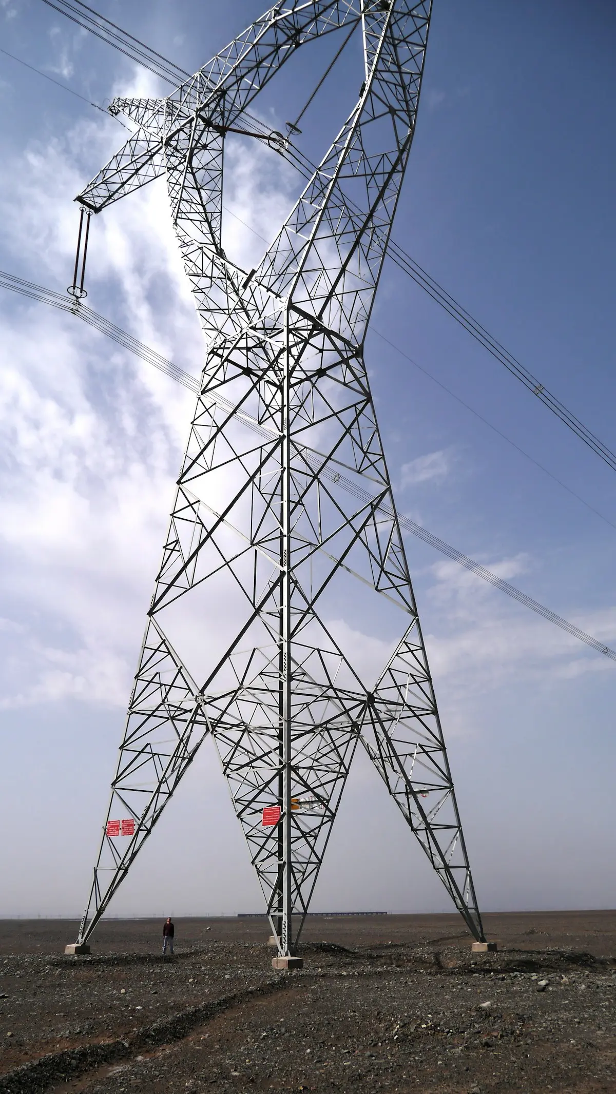
How Soil Testing Differs for Solar and Transmission
Solar arrays require broad, grid-based validation for wind uplift, while transmission projects demand deep, point-specific analysis to resist high-tension guy wire loads and mitigate long-term soil creep.
Sampling Strategy: Grid Density vs. Point Precision
The fundamental divergence in soil testing begins with the sampling area. For solar farms, the challenge is managing risk across vast acreage. Geotechnical engineers typically employ a grid-based sampling approach, often using methods like the Standard Penetration Test (SPT) or Dynamic Cone Penetrometer (DCP) at regular intervals (e.g., every 50 to 100 meters). The objective is to map the uniformity of the shallow soil layers—usually the top 1.5 to 2.5 meters—where ground screws or helical anchors will sit. This ensures that the racking system experiences consistent settlement behavior and that the array remains planar.
Conversely, transmission tower testing is highly localized and significantly deeper. Since a single anchor failure can compromise an entire span, testing focuses on the specific coordinate of each structure or anchor point. Engineers look beyond the topsoil to analyze deep strata mechanics, as transmission anchors—particularly helical types used for guy wires—often require depths exceeding 4 to 6 meters. The investigation prioritizes identifying distinct soil layers (sand, clay, rock) that could cause variable shaft friction or unexpected refusal during installation.
Load Validation: Proof Testing Protocols
While laboratory reports provide theoretical capacity, on-site proof testing remains the final arbiter for both sectors, yet the execution differs. In solar construction, proof loading is often a statistical process. Contractors may perform pull tests on a representative sample (e.g., 1% to 2% of the total anchors) to verify that the installation torque correlates with the theoretical holding capacity derived from the soil report. The primary failure mode being tested is vertical uplift to counteract wind forces on the panel tables.
Transmission protocols are far more rigorous regarding proof loading. Given the critical nature of grid infrastructure, proof testing frequently targets 100% of guy anchors or utilizes a higher statistical sampling of tension anchors. The test loads are typically a higher percentage of the ultimate capacity (often following ASTM D3966 or IEEE standards) to simulate extreme weather events. Unlike solar, where a slight shift might only require panel adjustment, anchor creep or movement in a transmission line can alter wire tension, leading to cascading structural failures.
The Critical Role of Soil Creep Analysis
A critical but often overlooked difference is the analysis of soil creep, particularly in cohesive soils like clay. For solar foundations, some long-term settlement is structurally permissible provided it is uniform across the array. The testing focus is on bearing capacity to prevent the rack from sinking.
For transmission towers, especially those using guy wires, soil creep is a "red flag" parameter. If an anchor experiences gradual downward movement (creep) under constant tension, the guy wire will slacken, transferring dynamic loads onto the pole structure which it is not designed to handle. Consequently, transmission soil testing must include consolidation estimates and long-term deformation analysis, requiring more sophisticated triaxial testing or consolidation tests in the lab phase compared to the standard shear strength tests often sufficient for solar farms.

How Load Demands Compare for Solar and Transmission
Solar and transmission foundations operate on completely different force vectors. Photovoltaic racking relies on distributed compression and uniform static uplift across hundreds of anchor points, while transmission towers concentrate massive dynamic line tension into a single location, generating severe overturning moments that require deeper soil engagement and heavier shaft geometry.
Solar Racking Loads: Distributed Compression and Static Uplift
A utility-scale solar array transfers structural weight through a grid of low-profile mounting rails. Each foundation point carries a relatively modest compressive load from the module weight, combined with consistent thermal expansion cycles. When wind suction acts on the panels, the resulting tension is spread evenly across the field. This distribution means individual anchor points do not need to resist catastrophic single-axis failure. Instead, the design priority is dimensional consistency, uniform settlement prevention, and long-term fatigue resistance under cyclic loading.
Transmission Towers: Concentrated Overturning and Dynamic Line Pull
High-voltage corridors tell a different story. A single transmission structure supports heavy conductors, crossarms, and dynamic line tension that can shift rapidly during ice accumulation or emergency conductor breakage. Unlike solar racking, the load path is highly concentrated. The foundation must absorb massive overturning moments that attempt to rotate the tower around its base. This requires helix configurations that dig deeper into stable soil strata and shaft geometries engineered to resist bending stress without plastic deformation.
Why Generic "High Load Capacity" Ratings Mislead Procurement Teams
Specification sheets frequently highlight a single maximum pull-out number, which creates a dangerous illusion of interchangeability. A solar ground screw rated for high compression does not automatically translate to transmission-grade performance. The difference lies in how the load is transferred into the soil. Solar anchors prioritize broad plate surface area and rapid deployment efficiency. Transmission anchors prioritize helix pitch optimization, shaft tensile strength, and resistance to rotational shear under asymmetric loading. Swapping one for the other compromises the entire load path.
- Load Path Direction: Solar systems manage vertical gravity and evenly distributed uplift, whereas transmission structures battle lateral overturning forces and concentrated conductor tension.
- Helix Geometry Priority: Solar designs favor wider plate spacing for rapid installation and soil displacement control. Transmission designs require tightly engineered pitch ratios to maintain stability under asymmetric dynamic stress.
- Failure Tolerance: A single underperforming solar anchor can often be compensated by adjacent mounting points. A transmission foundation failure directly threatens grid integrity and requires zero-defect load validation.
Marketing materials often push "universal" ground screws for both applications to simplify purchasing. Treat any claim of equal performance across solar and transmission classes with skepticism. If the manufacturer cannot provide separate load-path engineering documentation, specify distinct products for each infrastructure type.
Speed of Installation Versus Long-Term Structural Confidence
The construction industry has grown accustomed to poured concrete footings because they offer predictable curing timelines and decades of historical precedent. Ground screws eliminate cure wait times and reduce site excavation, but that speed occasionally triggers valid concern regarding immediate holding strength. The reality is that screwed foundations derive capacity from mechanical interlock with compacted soil layers, not chemical bonding. When installed to verified torque-to-load correlations, the holding capacity is measurable and repeatable from day one. This removes the variable of concrete quality control, which is highly sensitive to mix ratios, moisture content, and environmental curing conditions during placement.
For EPC contractors managing tight grid-connection deadlines, understanding the fundamental difference between distributed solar compression and concentrated transmission overturning prevents costly redesigns during commissioning. Selecting the correct foundation architecture upfront ensures that each anchor point performs exactly within its intended load envelope, regardless of site accessibility or schedule pressure.
| Load Parameter | Solar Foundation Demand | Transmission Foundation Demand | Rax Power Engineering Response |
|---|---|---|---|
| Tensile / Pull-Out Resistance | Moderate uplift resistance against distributed wind suction across photovoltaic arrays. | Extreme high-breaking load tolerance to stabilize towers under severe wind, ice, and seismic stress. | Hot-forged helical shafts with optimized plate geometry, validated through IEC 120 pull-out testing. |
| Compressive / Vertical Bearing | Medium bearing capacity focused on settlement prevention and soil compaction along continuous threads. | High axial compressive strength required to support heavy conductors, crossarms, and dynamic line tension. | Hot-forging automation ensures superior shaft integrity and dimensional precision for uniform vertical load distribution. |
| Corrosion & Service Life | 25–30 year outdoor durability in varied agricultural or coastal terrain with minimal maintenance. | 30–50 year infrastructure lifespan across harsh climates, including extreme cold and high humidity. | Hot-dip galvanizing compliant with ISO 1461 and ASTM A153 Class C, ensuring a mean coating thickness exceeding 85 microns. |
| Installation Torque & Depth | Rapid powered installation without concrete curing, enabling fast utility-scale rollout and site reversibility. | High-torque mechanical driving into stable strata, frequently requiring custom extension rods to bypass unstable soil. | Compatible with hydraulic screw-pile drivers; full OEM/ODM capability with custom drive adapters and engineered extension solutions. |
| Quality Validation Protocol | Verified holding strength through standardized load and gauge testing for EPC contract compliance. | Rigorous in-house load testing with zero-defect tolerance due to critical grid safety requirements. | 10-person QC team executes 100% dual-stage inspection, with holding strength verified via IEC 120 and independent SGS load testing. |
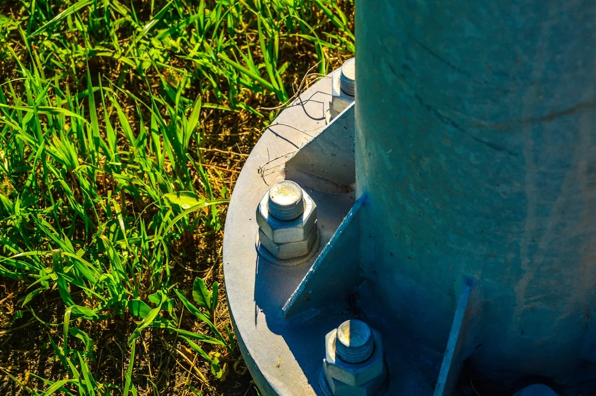
Galvanized Steel for 25-Year Solar and 50-Year Towers
Key Takeaway: The viability of galvanized steel anchors beyond their service life hinges on zinc coating density, not just steel thickness. A mean coating exceeding 85 microns acts as the primary differentiator between a 25-year solar asset and a 50-year transmission foundation.
Debunking the "Disposable" Myth in Ground Screw Engineering
A significant skepticism among utility project managers and solar EPCs is the perception that galvanized ground screws—often marketed as "fast and cheap"—are structurally inferior to concrete foundations. The fear is not that the steel will snap, but that corrosion will eat through the zinc layer, leading to premature rust and structural compromise within a decade. This concern is valid only if the galvanization process fails to meet industrial benchmarks. In reality, the corrosion protection mechanism relies on the zinc acting as a sacrificial anode, corroding preferentially to the steel substrate. The critical variable is the thickness of this barrier.
The 85-Micron Benchmark: ISO 1461 Compliance
To ensure longevity, manufacturers must adhere to strict hot-dip galvanizing standards. The industry baseline for quality assurance is ISO 1461, which governs the coatings applied to iron and steel articles. While entry-level competitors may hover around the minimum 60–70 micron range, high-performance specifications demand a more substantial buffer.
- Mean Coating Thickness: Premium-grade pole line hardware and ground anchors typically exceed 85 microns. This additional 15–20 microns of zinc can add decades of service life in moderate soil conditions.
- Surface Quality: The finish must be smooth and bright, free from slag, ash, or bare spots. A rough finish often indicates poor pre-treatment, which can trap moisture against the steel and accelerate localized corrosion.
- Material Consistency: Underlying steel, typically Q235B for general applications, must be properly pickled and fluxed to ensure the zinc metallurgically bonds to the surface rather than just sitting on top.
Mapping Service Life: 25-Year Solar vs. 50-Year Towers
The distinction between a solar farm and a transmission tower is not just the load, but the expected design life. Solar projects are generally capitalized for a 25-year operational cycle, while utility transmission infrastructure is engineered for 50+ years. Therefore, the galvanization strategy must scale accordingly.
For 25-year solar applications, a mean coating thickness of >85 microns is typically sufficient to withstand atmospheric and soil corrosion, provided the soil pH is not aggressively acidic. However, for 50-year transmission towers, the margin for error is zero. Engineers often specify heavier coating weights or require secondary protection measures for the below-grade section of the anchor. In this context, a manufacturer that consistently delivers >85 microns provides a necessary safety buffer, ensuring that even with natural zinc consumption over five decades, the steel substrate remains protected well beyond the asset's depreciation schedule.
Verification Protocols for Buyers
To verify that the "85 micron" claim is not marketing fluff, buyers must demand non-destructive testing reports. A magnetic thickness gauge should be used on random samples from the batch—not just the top layer of the shipping crate. Variance is acceptable, but any reading falling below 70 microns on a product rated for heavy-duty utility use constitutes a failure to meet ISO 1461 standards for structural safety.

Access Challenges for Solar Farms and Transmission Routes
Terrain Geometry and Rig Selection
Access constraints are rarely uniform between solar farm developments and linear transmission corridors, even though both rely heavily on screwed foundation systems. Solar projects typically occupy expansive, relatively flat plots where equipment mobilization follows a planned grid pattern. Transmission routes, however, traverse narrow rights-of-way, steep gradients, and ecologically sensitive zones where heavy machinery simply cannot follow the proposed alignment. This fundamental difference dictates the selection of installation rigs, the achievable deployment rate, and the level of specialized training required to hit target torque values safely.
Solar farm sites often allow standard excavator-mounted torque heads because the ground is graded and the array layout provides clear access lanes. Contractors can maintain high cycle rates, frequently completing multiple piles per hour once the base equipment is positioned. Transmission infrastructure tells a different story. The corridor width may be only a few meters, and slopes can exceed 30 degrees. In these conditions, full-sized rigs must be replaced with compact, track-mounted, or manually carried rotary drives. The switch in equipment directly reduces installation speed and increases the reliance on experienced operators who understand how to stabilize a rig on uneven ground while maintaining vertical alignment.
- Solar Farm Mobilization: Standard excavators with quick-attach torque heads work efficiently on cleared, flat terrain with wide access paths.
- Transmission Corridor Mobilization: Compact rotary drives, winch-assisted track carriers, or sectional rig components are required to navigate narrow, sloped, or restricted rights-of-way.
- Speed Variance: Deployment rates drop significantly when moving from open-field solar layouts to constrained linear routes, requiring tighter schedule buffers.
DIY Feasibility Versus Professional Installation Demands
The question of whether ground screw installation can be handled as a do-it-yourself project depends entirely on the application scale and load class. For low-load solar mounting points in accessible agricultural fields, smaller hydraulic or electric rotary tools can sometimes be operated by trained crews without needing certified heavy equipment. However, this flexibility vanishes the moment the foundation enters a transmission or high-wind uplift category.
Structural safety for transmission anchors relies on hitting precise torque-to-capacity thresholds. Soil resistance varies along a route, meaning a pile that meets specifications at one location may require additional revolutions or a different helix configuration at the next. Without professional torque monitoring equipment and field engineering oversight, there is no reliable way to verify that the anchor has achieved its design load. Attempting to install high-strength guy wire anchors, transmission towers, or heavy-duty support structures with uncalibrated handheld tools introduces unacceptable risk of under-driven foundations or twisted shaft damage.
- Torque Verification: Professional rigs include calibrated telemetry that records final torque in real-time, providing the documentation utilities and engineers require for commissioning.
- Alignment Control: Off-vertical installation reduces lateral holding capacity. Trained operators use guide frames or hydraulic positioning to keep the screw within acceptable plumb tolerances.
- Site Adaptation: Unforeseen subsurface obstructions or rock layers demand immediate adjustment to installation strategy, something ad-hoc crews are not equipped to handle safely.
Relying on manual installation for anything beyond small-scale solar racking ignores the torque calibration requirement. An under-torqued anchor may appear fully seated but will fail under service loads. Always verify that the installation contractor carries certified torque logging equipment and follows the geotechnical design report.
How Easy Is Land Recovery for Solar Versus Towers
Land restoration is fundamentally asymmetric: solar arrays require complete reversibility for leased land, whereas transmission towers are generally treated as permanent assets where abandonment is the standard decommissioning protocol.
Reversibility Dynamics in Solar Foundations
In the utility-scale solar sector, land lease agreements typically mandate "zero trace" decommissioning. This contractual obligation makes the choice of anchor critical. Round shaft helical piles are the preferred solution for these projects because they offer 100% recoverability. Unlike concrete footings which require demolition and haul-away, helical piles can be extracted using the same hydraulic drive equipment used for installation. The extraction process generally requires less torque than installation because the soil has relaxed, though this depends heavily on soil consolidation over a 25-year lifecycle.
The primary advantage for developers is the preservation of topsoil integrity. Because the installation involves a small pilot hole rather than wide trenching, the stratigraphy of the soil remains undisturbed. Upon removal, the narrow shaft hole can be backfilled with native soil, allowing the land to immediately return to agricultural use without the subsidence risks associated with large concrete excavation.
Transmission Anchors and Abandonment Protocols
Conversely, land recovery for transmission towers is rarely a priority during the initial engineering phase. These assets are installed on permanent easements with lifespans exceeding 50 years. The anchors used—typically expanding anchors, heavy-duty square shaft helical piles, or cross-plate anchors—are engineered for maximum permanent grip rather than removability. Specifically, square shaft configurations, while offering superior torque resistance and high pull-out ratings for guy wires, are prone to binding during extraction attempts due to soil friction against the square edges.
In the utility industry, the standard practice for decommissioning transmission lines is often "abandonment in place." Attempting to extract deep-set transmission anchors poses significant logistical challenges. The shafts can extend 20 to 40 feet below grade, and the force required to break the soil suction can damage surrounding cabling or adjacent foundations. Consequently, decommissioning budgets usually account for cutting the anchor off at grade level and capping it, rather than full extraction.
Coating Integrity and Extraction Risks
A critical technical factor in land recovery is the condition of the steel's corrosion protection system after decades of burial. For solar projects where extraction is mandatory, anchors rely on hot-dip galvanizing with a mean coating thickness generally exceeding 85 microns to prevent corrosion-welding to the soil. If the coating integrity is compromised by aggressive soil chemistry, the steel surface roughens, increasing friction with the soil and making extraction mechanically difficult. If an anchor cannot be removed cleanly, the contractor risks shearing the shaft, leaving a dangerous obstruction underground and failing the land restoration requirement.
- Soil Displacement: Helical piles displace less than 5% of the soil volume compared to concrete piers, facilitating immediate land reclamation.
- Shaft Geometry: Round shafts allow for "unscrewing" the anchor; square shafts often require heavy machinery to pull vertically, increasing cost and surface disturbance.
- Decommissioning Cost: Solar pile extraction is fast and low-impact; transmission anchor removal is often cost-prohibitive, leading to abandonment clauses in right-of-way agreements.
For solar projects on rented agricultural land, mandate "reverse-torque testing" during the pilot phase. This verifies that the specific soil type will not seize the helix over time, ensuring the theoretical "100% recovery" is actually physically possible at the end of the lease.
Cost Differences Between Solar and Transmission Ground Screws
Solar farm anchors compete on per-unit volume pricing and fleet installation speed. Transmission anchors compete on shaft integrity and validation cost. The equipment bill follows different curves.
Volume Pricing Tiers for Solar Farms
Utility-scale solar sites operate on a fundamentally different commercial model than power grid infrastructure. Procurement teams typically move thousands of no-wrench screw anchors per project, which allows suppliers to structure pricing around volume brackets rather than individual unit quotes. When you lock in tiered purchasing, the anchor itself becomes a commodity-grade component with tight margin expectations.
The reason standardization matters at this scale is that field crews can rotate through identical installations without retooling or retraining. Automated hot-forging lines produce consistent dimensional accuracy across large batches, which means a solar EPC can expect every anchor arriving on site to match the previous one. That repeatability is what makes volume discounts commercially viable.
- Bulk order brackets: Pricing structures shift at common deployment thresholds, rewarding committed project quantities with predictable per-unit economics.
- Standardized no-wrench designs: Simplify handling and reduce labor overhead across thousands of installation points.
- Extension rod flexibility: Sites with variable topography can use custom extension rods to bypass unstable soil without changing the anchor platform itself.
In our experience, the hidden cost variable on solar projects is rarely the anchor price itself—it is the supply chain consistency. A delayed shipment of ten thousand anchors stalls an entire field crew. That is why manufacturers with high-volume automated capacity and documented QC protocols matter more to solar procurement than margin shaving on a single unit.
Heavy-Duty Steel Costs for Transmission Stability
Transmission ground screws sit on the opposite end of the cost spectrum because they are engineered for extreme environmental stress and long-service structural demands. The material specification alone drives unit costs higher—thicker shafts, heavier forging profiles, and more rigorous metallurgical validation are non-negotiable when a guy wire or tower leg depends on that anchor for decades.
The premium here is not simply about using more steel. It is about the manufacturing process that produces that steel. Hot-forging automation delivers superior shaft integrity and dimensional precision compared to traditional casting methods, which matters significantly when failure tolerance is effectively zero. Every anchor leaving the line carries validation data, not just a certificate.
- Shaft integrity engineering: Higher breaking load requirements demand robust forging specifications that increase material and processing costs.
- Validation burden: Rigorous in-house load and gauge testing per international utility standards adds cost per batch but protects project budgets from field failures.
- Double-review inspection protocols: A dedicated QC team conducting 100% two-pass inspections reduces failure risk and rework costs on critical infrastructure.
Our team sees this gap clearly every quarter. Solar clients optimize for speed and scale. Transmission clients optimize for certainty. The cost structure reflects that difference, and any supplier claiming equal performance on both markets without clear engineering separation is usually hiding somewhere in the middle.
Installation Machinery Rental and Time Analysis
The machinery question is where project economics actually converge. Both solar and transmission ground screws replace concrete piers, which eliminates curing wait times and opens up faster deployment windows. However, the rental footprint and operational tempo differ enough to affect total installed cost.
Solar farm installations favor rapid fleet deployment. Field crews work through standardized anchor patterns at high rotation speeds, meaning machinery utilization centers on throughput rather than precision calibration. Transmission routes demand more measured installation节奏, where each anchor must achieve verified structural seating before moving to the next position. The machinery cost per hour may be similar, but the time allocation per anchor diverges significantly.
- Fleet installation speed: Standardized no-wrench screw designs support rapid deployment across large solar footprints with minimal reconfiguration.
- Precision installation pacing: Utility routes prioritize immediate structural safety verification, which changes how long machinery stays on site per anchor.
- Concrete lead time elimination: Powered installation for both sectors removes curing delays, labor bottlenecks, and extensive site restoration costs.
Procurement teams often underestimate the machinery logistics budget until mobilization day. Solar projects burn through equipment fast but cover massive acreage. Transmission projects move slower per anchor but traverse longer linear distances with stricter clearance windows. The total installed cost tells a different story than the per-unit anchor price alone.
| Parameter | Solar Ground Screw Profile | Transmission Ground Screw Profile | Cost Implication | Rax Power Capability |
|---|---|---|---|---|
| Load Capacity & Design | Optimized for distributed module arrays with moderate tension/compression loads across large utility-scale footprints. | Engineered for high-breaking load requirements, guy wires, and extreme environmental stress on power grids. | Transmission anchors carry higher unit costs due to robust shaft integrity and heavy-duty forging specifications. | Hot-forging automation delivers superior shaft integrity and dimensional precision, outperforming traditional casting methods for both applications. |
| Corrosion Protection | Standard durability sufficient for renewable energy sites with consistent exposure profiles. | Enhanced resilience required for harsh, coastal, industrial, or extreme-climate infrastructure environments. | Premium coating costs are justified by longevity; Rax standard exceeds baseline requirements for both sectors. | Hot-dip galvanizing compliant with ISO 1461 and ASTM A153 Class C, ensuring a mean coating thickness exceeding 85 microns. |
| Soil Adaptation & Depth | Flexible layouts accommodate variable screw depths based on site topography and soil conditions. | Deep anchoring often necessary to bypass unstable surface layers and ensure maximum holding strength. | Custom extension rods eliminate expensive excavation and concrete piers while maintaining structural reliability. | Custom extension rods available to bypass unstable soil, delivering engineered solutions for complex terrain. |
| Quality Assurance & Validation | High-volume consistency is critical to support rapid EPC deployment schedules. | Rigorous in-house load and gauge testing is mandatory per strict international utility standards. | Double-review protocols reduce failure risk and rework costs, protecting project budgets across all applications. | A 10-person QC team executes a 100% double-review inspection protocol, supported by IEC 120 load testing and SGS certification on all products. |
| Installation Efficiency | Speed-critical deployment favors standardized no-wrench screw designs for rapid fleet installation. | Precision installation ensures immediate structural safety without waiting for concrete curing times. | Powered installation for both eliminates concrete lead times, labor bottlenecks, and extensive site restoration. | High-volume automated capacity supports powered installation for both sectors, delivering spec-compliant anchoring systems designed for maximum reliability. |
Conclusion
Solar projects win on installation speed when you switch to ground screw foundations. Transmission routes demand more torque and deeper helix engagement, so you size those anchors based on raw soil density before mobilizing crews. We've seen dealers lose margin guessing helix diameter instead of running standard penetration tests. Your engineers should lock the load capacity table against local soil classes, then order the matching galvanized steel spec. That discipline protects your warranty claims down the line.
- Request site-specific soil reports before quoting volume orders.
- Confirm ASTM A153 hot-dip galvanizing for every anchor type.
- Contact our engineering team with early-stage design questions—no obligation, just technical backup for your racking and tower layouts.
Frequently Asked Questions
How do ground screws work?
Ground screw foundations transfer structural loads through helical plates embedded in the soil. As the shaft rotates during installation, the plates grip surrounding earth layers to resist uplift and compression forces. This mechanical anchoring eliminates the need for poured footings or curing time. At Raxpower, we design these systems to match specific geotechnical requirements for both renewable and utility projects.
What soil types suit them?
Helical anchors perform best in cohesive soils, loose sands, and mixed granular profiles where mechanical interlock is achievable. They can bypass weak surface layers using custom extension rods to reach competent bearing strata. Highly rocky, karst, or organically saturated peat soils generally require alternative foundation strategies. A geotechnical report should always precede anchor selection and depth calculations.
How do solar foundations differ?
Solar ground screws prioritize broad uplift resistance and rapid field installation across large acreage. Transmission foundations emphasize higher breaking loads, corrosion protection, and compatibility with tensioned conductors or crossarms. Both applications use similar helical mechanics but differ in plate geometry and shaft reinforcement. Project engineers select configurations based on line loading, module weight, and local code requirements.
Are they better than concrete?
Ground screws typically reduce foundation costs by removing material expenses, curing delays, and heavy excavation. They offer faster deployment and reversible installation, which simplifies future site decommissioning. However, concrete may still be preferred for extremely shallow bedrock or specialized seismic zones. Engineers usually select between the two based on soil bearing capacity and project timeline constraints.
Can contractors install them DIY?
Professional powered installation is strongly recommended due to the torque requirements and precision needed for load-rated anchoring. Standard hydraulic drivers mounted on excavators or skid steers achieve consistent penetration without damaging the shaft. Manual driving is impractical for commercial-scale utility or solar arrays. Certified contractors ensure proper alignment, torque verification, and compliance with engineering specifications.