
Most procurement files for basement wall anchors treat galvanizing and steel grade as checkbox items. They aren’t. When lateral soil pressure pushes against a bowed concrete block wall, a thin zinc coat or an off-gauge tie rod doesn’t just fail quietly. It triggers a non-conformance report on a job site three states away. Baseline compliance starts with ASTM A153 minimum average coating mass requirements, and anything below the specified thickness for heavy-section fasteners leaves threaded connections exposed to aggressive soils well before warranty day one.
You need hard limits on tensile strength, hot-forged versus cast steel geometry, and a clear method to verify coating thickness against ISO 1461 before approving a production batch. The following sections show how to cross-reference proof-load test data against dimensional drawings so the hardware you receive actually matches the spec sheet your engineers signed off on. Get the material grades right upfront, and you remove the single biggest variable in foundation repair re-work costs.
Why Anchor Specs Prevent Wall Failure
Wall failures rarely happen suddenly—they progress through material yield, coating degradation, and anchor pullout when specifications fall short of actual soil demands.
Tensile Strength Thresholds for Resisting Hydrostatic Pressure
When drainage systems fail or seasonal moisture saturates backfill, hydrostatic pressure becomes a sustained lateral load pushing directly against your basement walls. The tieback rod and buried anchor must transfer that force into undisturbed soil without yielding, buckling, or pulling free. A spec that looks adequate on paper often collapses under long-term cyclic loading, especially when water tables fluctuate seasonally.
The critical distinction is between peak pull-out rating and sustained holding capacity. Manufacturers publish maximum force values, but real-world performance depends on fatigue resistance across thousands of pressure cycles over a structure’s service life. Our engineers reject installations where the rated anchor capacity does not provide a meaningful safety margin above calculated hydrostatic demand, because a single catastrophic failure point transfers stress to adjacent anchors and accelerates wall movement.
- Sustained Load Rating: Specify anchors tested under repeated cyclic conditions, not just one-time static proof loads.
- Factor of Safety: Design systems with capacity exceeding worst-case hydrostatic calculations by a wide margin to account for long-term soil settlement and coating thinning.
- Corrosion Allowance: Account for cross-sectional loss over decades; a rod that passes initial load tests may still fail prematurely if material thickness is marginal.
Steel Grade Selection for High-Load Foundation Applications
Foundation anchor steel sits in a hostile environment where both strength and ductility must coexist. Low-grade carbon steel yields permanently under heavy lateral pressure, while overly hard alloy steel can snap catastrophically without warning. The ideal specification balances high yield strength with enough elongation to redistribute stress rather than propagate fractures through micro-cracks introduced during installation.
Base metallurgy determines whether an anchor survives decades of buried service or degrades within a few seasons. Higher-grade steel alloys provide superior tensile performance and resist plastic deformation when exposed to continuous soil pressure. We select mill-certified materials and apply controlled heat treatments to maintain consistent mechanical properties across every production batch, ensuring that each anchor performs predictably under design load.
For projects targeting extreme climates or high-breaking load requirements, our technical team develops custom material specifications that exceed standard utility grades. Whether serving cold-weather demands in northern markets or high-tier quality standards for regional utilities, we adjust alloy composition and thermal processing to maintain structural integrity across temperature extremes.
Anchor Plate Geometry Impact on Soil Holding Capacity
The buried anchor plate is where theoretical holding power becomes physical reality. Plate diameter, pitch angle, flight count, and shaft configuration all determine how effectively the anchor engages undisturbed soil layers. Poor geometry spreads load inefficiently, allowing soil to shear around the plate rather than compressing against it to generate passive resistance.
Helical designs rely on screw-action mechanics—each rotation displaces and compacts soil against the plate face, creating a dense bearing zone that resists pullout. Round-shaft helicals offer consistent torque-to-capacity correlation, making installation verification more predictable. Square-shaft and cross-plate configurations serve different engagement profiles depending on whether the target stratum is clay, silt, sand, or rock-adjacent material.
Installation torque is not merely a procedural checkpoint—it is the primary field indicator that plates have penetrated past loose fill and reached competent undisturbed soil. When torque values lag behind expectations, it usually signals that plates are cutting through weakened or saturated zones rather than achieving full soil engagement. Our production team designs plate geometries to provide clear torque response curves, allowing contractors to confirm embedment depth and holding performance during installation without relying solely on visual inspection.
Specifying anchor geometry based only on catalog pull-out numbers ignores soil-specific engagement behavior. Always match plate configuration and shaft profile to the actual borehole strata encountered during excavation, not the worst-case assumption on a generic spec sheet.
| Anchor Specification | Technical Requirement | Applicable Standard | Wall Failure Prevention |
|---|---|---|---|
| Ultimate Tensile Capacity | Sustains up to 18,000 lbs pull-out force | IEC 120 In-House Load Testing | Neutralizes hydrostatic pressure and prevents lateral bowing without plastic deformation |
| Corrosion Protection Layer | Hot-dip galvanized finish exceeding 85 microns thickness | ISO 1461 and ASTM A153 | Eliminates rust-induced cross-sectional loss that compromises anchor holding power in moist soil |
| Steel Forming Process | Hot-forged construction with automated welding for optimized grain structure | Rax Power Dimensional Precision Protocol | Prevents structural micro-fractures and anchor pull-through under dynamic soil loads |
| Torque Application Rating | Withstands installation torque up to 2,300 ft-lbs | Rax Power High-Torque Fatigue Protocol | Ensures secure anchoring in dense soil without mechanical shearing during installation |
| Quality Assurance Protocol | 100% double-review inspection by dedicated 10-person QC team | SGS Certified Verification | Eliminates manufacturing defects that compromise anchor embedment and verified load transfer |
Hot-Forged Steel Delivers More Strength Than Castings
Hot-forged steel offers superior structural integrity and fatigue resistance compared to castings, making it the critical choice for high-load utility infrastructure.
The Metallurgical Physics of Grain Alignment
The fundamental disparity between hot forging and casting lies in the internal grain structure of the steel. In the casting process, molten metal is poured into a mold; as it cools and solidifies, the steel grains form in a random, dendritic pattern. This amorphous structure creates natural weak points where stress can concentrate, significantly reducing the overall tensile strength of the component. Conversely, hot forging involves heating steel billets to a plastic state and applying massive compressive force—often thousands of tons—to shape the metal.
This mechanical pressure causes the steel grains to recrystallize and align along the contour of the part. For critical pole line hardware such as eye bolts, guy clamps, and anchor rods, this continuous grain flow allows the material to withstand multi-directional stress loads effectively. The result is a component that possesses significantly higher ductility and shock resistance, attributes that are non-negotiable for overhead lines exposed to dynamic wind loads and vibration.
Porosity Elimination and Structural Density
One of the most pervasive failure modes in cast hardware is porosity. As molten metal cools and shrinks, air pockets and voids can become trapped within the structure, leading to what engineers term “inclusions.” These internal cavities act as stress risers, which can propagate cracks under heavy tension, resulting in sudden catastrophic failure. This risk is amplified in harsh environments where freeze-thaw cycles or corrosion can exploit these microscopic voids.
Hot forging bypasses this issue entirely by working with a solid billet. The extreme compressive pressure of the forging process squeezes out impurities and welds internal voids shut, yielding a near 100% dense metal structure. For helical anchors and cross-arm braces, this structural density translates directly to a higher safety factor. Field data and load testing consistently demonstrate that hot-forged components exhibit superior fatigue life, enduring repeated load cycles without the material degradation common in porous cast equivalents.
Dimensional Precision and Tolerance Control
Beyond pure strength, the manufacturing method dictates the geometric reliability of the hardware. Cast parts are prone to shrinkage and warpage as they cool, resulting in dimensional variances that can complicate installation on utility poles. If a guy clamp or cross-arm bracket is out of tolerance by even a few millimeters, it can compromise the assembly’s stability or necessitate hazardous field modifications.
Advanced hot-forging processes, utilizing automated and semi-automatic machinery, ensure superior dimensional accuracy. While traditional casting methods may struggle with inconsistent wall thickness, high-end forging operations can maintain strict tolerances—often within 1mm—ensuring that every U-bolt or helical anchor fits perfectly without gaps. This precision is vital for B2B buyers managing bulk installations, as it reduces labor costs associated with re-work and ensures consistent performance across the entire infrastructure project.
- Grain Flow: Forging aligns the steel grain structure to the shape of the part, whereas casting creates a random, weaker structure.
- Density: The compressive force of forging eliminates porosity and air pockets found in castings.
- Impact Resistance: Forged steel absorbs high-impact energy without fracturing, crucial for extreme weather environments.
- Tolerance: Forging achieves higher dimensional consistency (e.g., 1mm tolerance) compared to the variability of cast molds.
Why Hot-Dip Galvanizing Protects Anchors Best
Hot-dip galvanizing outperforms paint and electro-galvanizing because it creates a metallurgical bond with a mean coating thickness exceeding 85 microns, delivering both barrier protection and cathodic defense against aggressive underground environments.
The Metallurgical Bond Advantage
When helical anchors are driven into soil, they endure constant abrasion from rocks, clay, and root systems. Standard paint or powder coatings rely on mechanical adhesion, meaning they can chip or peel when the anchor encounters dense obstructions. Hot-dip galvanizing solves this by creating a metallurgical bond where zinc reacts with the steel substrate to form iron-zinc alloy layers. This fused layer does not flake, even if the anchor is scraped during installation.
Electro-galvanizing, while smoother, typically deposits a coating far too thin for underground utility or foundation applications. For anchors subjected to hydrostatic pressure and soil chemistry, the thicker deposit achieved through hot-dip processing provides the necessary resilience. Premium specifications, such as those aligned with ISO 1461, ensure the coating remains consistent across complex geometries, including helical flights and threaded ends.
Sacrificial Cathodic Protection Mechanism
Beyond acting as a physical barrier, the zinc coating provides active electrochemical protection. In the galvanic series relevant to soil and water environments, zinc is positioned anodically to carbon steel. This means that if the coating is breached and the underlying steel is exposed to moisture, the zinc will preferentially corrode rather than the steel.
- Anodic Priority: Zinc sacrifices itself to protect the steel substrate, preventing rust formation at scratches or cut edges.
- Edge Protection: Unlike paint, which can fail at sharp edges, molten zinc flows and bonds at all contours, ensuring no weak points for corrosion to initiate.
- Long-Term Stability: This cathodic action continues as long as zinc remains adjacent to the steel, extending the service life of the anchor significantly in corrosive soils.
Thickness Standards and Service Life
Coating thickness is the primary determinant of corrosion resistance life. Industry standards like ISO 1461 define the minimum requirements for hot-dip galvanized coatings on fabricated steel products. High-performance anchors manufactured to rigorous export standards typically achieve a mean coating thickness exceeding 85 microns, providing a robust shield against aggressive environments.
A smooth, bright finish often indicates a well-controlled galvanizing process with proper fluxing and temperature management. This visual quality correlates with dense, uniform alloy layers that resist degradation. For B2B buyers specifying anchors for critical infrastructure, verifying compliance with these thickness standards is essential to ensure the hardware meets the projected lifespan of the power or solar foundation project.
Always request certification data confirming the mean coating thickness per ISO 1461. A “shiny” appearance alone does not guarantee sufficient zinc mass; quantitative verification protects against under-specified shipments.
Full Encapsulation for Complex Anchor Geometry
Helical anchors and earth screws feature intricate shapes, including flight edges, central shafts, and internal threads. Painting these components uniformly is nearly impossible without missing recessed areas. Hot-dip galvanizing immerses the entire assembly in molten zinc, ensuring complete encapsulation of every surface, including hard-to-reach inner threads and welded joints.
This uniform coverage is critical for maintaining the structural integrity of the anchor system. Unprotected threads can rust seized, making future inspection or removal difficult. By guaranteeing full metallurgical protection across the entire component, hot-dip galvanizing reduces lifecycle maintenance risks and ensures reliable performance in demanding ground conditions.
Choose Anchors Based on Local Soil Chemistry
Soil chemistry is the primary variable determining anchor service life. Before specifying helical screw anchors, expanding anchors, or cross-plate designs, procurement teams must align the protective coating system with local pH, chloride, and sulfate concentrations.
Soil Corrosivity Classification
Utility projects and solar foundations fail prematurely not because of structural overload, but because the surrounding ground chemically attacks the steel. Soil corrosivity is generally categorized into four tiers based on resistance to metal deterioration.
- Low: Dry, well-drained sands with neutral pH (6.5–7.5) and minimal chloride content.
- Moderate: Silty clay loams with occasional moisture saturation and pH values between 6.0 and 8.0.
- High: Peat, organic soils, acidic clays below pH 5.5, or reclaimed land with elevated sulfate concentrations.
- Very High: Coastal zones exposed to marine aerosols, road-deicing salt runoff, or industrial sites containing aggressive acids and chlorides.
Required Coating Performance by Exposure Tier
A standard mill-galvanized finish is rarely sufficient for high or very-high corrosivity zones. Hot-dip galvanizing remains the baseline specification for export-grade earth anchors because it provides both physical barrier protection and cathodic sacrificial defense.
- Average coating thickness: Exceeds 85 microns per ISO 1461, ensuring prolonged zinc consumption before base steel exposure.
- Local minimum threshold: Typically 70 microns at any single measurement point, preventing early rust formation in low-zinc areas.
- ASTM A153 compliance: Defines requirements for zinc coatings on iron and steel hardware, including weight gain, adherence, and drainage hole specifications.
- Duplex systems: Projects in very-high corrosivity environments often specify epoxy powder coatings applied over a galvanized substrate, targeting total dry film thicknesses above 200 microns.
Hot-Dip Galvanizing vs. Alternative Surface Treatments
Procurement teams frequently confuse electroplated, painted, and mechanical galvanized finishes with true hot-dip protection. For helical screw anchors driven through abrasive soil, thin zinc plating usually measuring 5 to 15 microns fractures during installation and offers negligible long-term corrosion resistance.
Hot-dip galvanizing fuses zinc to the steel substrate at roughly 450°C. The resulting metallurgical bond survives driving torque, backfill abrasion, and hydrostatic pressure far better than cold-applied coatings. When the zinc layer eventually sacrifices itself, it corrodes uniformly rather than delaminating in sheets.
Field Verification and Spec Documentation
Soil chemistry can shift over the operational lifespan of a pole line or solar foundation. Urban fill soils may contain discarded concrete, construction debris, or chemical residues that create localized acidic pockets around anchor shafts.
Specifying anchors with certified coating thickness from the factory removes design-stage guesswork. Buyers should request independent test reports or SGS verification for every shipment, confirming that the galvanizing process meets the stated micron specification before the hardware reaches the job site.
⚠️ Critical Pitfall: Do not accept generic galvanized labels without micron-level verification. Zinc coatings below 50 microns can degrade completely within three to five years in moderately corrosive soils, leading to premature anchor failure and expensive excavation repairs.

Matching Holding Power to Specific Soil Types
Soil Bearing Capacity Dictates Anchor Selection
Holding power is not a fixed number—it scales directly with soil density, moisture content, and particle composition. A helical anchor performing reliably in dense clay may underperform in loose sand, regardless of its rated tensile strength. Utility engineers must match anchor geometry and installation depth to the specific geotechnical profile before procurement.
Soil classification systems such as USCS (Unified Soil Classification System) categorize ground conditions into broad groups: gravels, sands, silts, and clays. Each category exhibits different shear strength and frictional resistance. Anchor holding capacity derives primarily from two mechanisms—frictional resistance along the shaft and bearing resistance at helical plates or anchor heads. The dominant mechanism shifts depending on whether the soil is cohesive or granular.
Cohesive Soils: Clay and Silt Conditions
- Undrained shear strength: Typically ranges from 10 to 200 kPa for clays. Higher plasticity indices indicate greater long-term consolidation potential.
- Anchor performance: Expanding anchors and cross-plate designs generate superior holding capacity through bearing against undisturbed soil mass rather than relying solely on skin friction.
- Installation consideration: Saturated clays reduce effective stress around the anchor body. Over-consolidated clays may offer higher initial resistance but are susceptible to time-dependent creep under sustained loads.
For power transmission applications in cohesive substrates, helical anchors with round or square shafts provide predictable load distribution. The continuous thread engagement ensures uniform friction along the embedded length, which is critical when soil strata vary within the immediate anchorage zone.
Granular Soils: Sand and Gravel Conditions
- Relative density classification: Loose sands (N60 < 10) offer minimal passive resistance; medium-dense sands (N60 = 10–30) provide moderate holding capacity; dense gravels (N60 > 30) deliver maximum bearing resistance.
- Helical plate geometry: Larger diameter flight plates increase displacement volume and engage more soil mass, but require higher installation torque. Square-shaft helical anchors often outperform round shafts in granular media due to enhanced interlocking.
- Drainage behavior: Granular soils drain rapidly during installation. This prevents pore pressure buildup but means anchor performance depends entirely on effective stress, which decreases with rising water tables.
No-wrench screw anchors excel in accessible granular environments where rapid deployment across multiple guy wire or crossarm support points is required. Their self-tapping design eliminates the need for pre-drilled pilot holes, reducing installation time while maintaining consistent embedment depth.
Stratified and Variable Soil Profiles
Field conditions rarely present a single uniform soil layer. Most utility sites contain interbedded clay, silt, sand, and organic topsoil. When anchor installation spans multiple strata, holding capacity becomes a function of the weakest competent layer and the total shaft-soil interface area.
Do not assume published pull-out test values apply across all soil profiles. A rating established in dense clay may be misleading when the same anchor is installed in loose fill or peat. Always verify geotechnical reports for the specific installation coordinates rather than relying on regional averages.
Load Testing and Quality Verification
Manufacturer load ratings must be validated against recognized testing protocols. In-house proof-load testing per IEC 120 provides dimensional and mechanical verification before shipment. For export-grade hardware destined for high-breaking-load environments, third-party certification through SGS confirms compliance with declared specifications.
Hot-dip galvanizing meeting ISO 1461 standards ensures coating thickness exceeds 85 microns on average, protecting anchor integrity across corrosive soil chemistries while maintaining structural dimensions.
Spec Selection by Application Class
- Standard utility pole guying: Helical anchors with round shafts, minimum 85-micron galvanized coating, installed to engineering-specified torque thresholds.
- Solar foundation anchoring: Cross-plate or high-pitch helical designs for shallow bearing strata where deep penetration is restricted by bedrock or groundwater.
- Extreme environment installations: Oversized helical plates and reinforced shaft geometries for regions requiring elevated breaking loads beyond standard catalog ratings.
Matching holding power to soil type begins with understanding whether the ground fails through shear, compression, or progressive displacement. Anchor hardware selection should follow from that failure mode—not from generic manufacturer claims or one-size-fits-all catalog listings.
Do These Anchors Fit Your Foundation Type?
Selecting the correct anchor technology requires precise alignment between the specific soil mechanics, the structural base material, and the load geometry of the application.
The Terminology Trap: Distinguishing Structural Anchors from Soil Nails
A frequent source of specification errors in the field is the interchangeable use of terms like “soil nails,” “rock bolts,” and “tieback anchors.” While these systems may appear physically similar, their engineering functions and load capacities differ significantly. Using a soil nail—designed primarily for passive slope reinforcement—in a high-tension utility or solar application creates a critical failure point. Structural anchors, such as helical screw anchors or expanding anchors, are active systems engineered to resist specific pull-out loads. For project integrity, purchasers must verify that the bill of materials specifies anchors rated for tensile loading rather than mere soil retention.
Matching Anchor Geometry to Soil Conditions
The physical interface between the anchor and the ground determines the holding power. There is no “universal” anchor; the selection must be driven by a geotechnical analysis of the foundation type.
- Helical Anchors (Round vs. Square Shaft): These are ideal for tension loads in varying soil densities. Round shaft anchors typically offer lower installation torque, facilitating deep penetration in loose soils to reach stable strata. Square shaft anchors, with their higher torque ratings, provide aggressive penetration in dense or stiff soils, offering higher immediate capacity in shallower depths.
- Expanding and No-Wrench Anchors: These are specialized for scenarios where rotary installation is impossible due to obstructions or limited clearance. They rely on toggling mechanisms to lock into undisturbed soil, providing stability in holes drilled through existing fill or rocky terrain.
- Cross-Plate Anchors: Best suited for shallow utility applications in softer soils where the plate can provide direct bearing resistance against the earth.
Interfacing with Concrete, Masonry, and Stone Foundations
When anchoring structures supported by concrete pads, masonry piers, or stone foundations, the primary concern is pressure distribution. The anchor must transfer the load to the soil without inducing excessive stress on the structural base itself. For instance, a guy anchor installed too close to a concrete pole base can create a shear force that cracks the masonry. Engineering calculations must ensure the “failure cone” of the soil anchor extends well beyond the footprint of the concrete foundation. Furthermore, connecting hardware (such as guy clamps or eye bolts) must be hot-forged rather than cast to withstand the concentrated stress points at the junction with the concrete foundation or steel pole base.
Verifying Corrosion Resistance for Ground Contact
Foundations present a corrosive environment due to varying soil chemistry and moisture levels. A critical specification often overlooked is the galvanizing standard. While many suppliers offer standard zinc plating, industrial-grade earth anchors require compliance with ISO 1461 hot-dip galvanizing standards. This ensures a mean coating thickness exceeding 85 microns, providing the necessary barrier against soil-induced oxidation for the asset’s design life. Buyers should demand test certificates confirming this coating thickness, as sub-standard galvanizing is the leading cause of anchor failure in aggressive soils.
Always require torque-to-capacity correlation charts for helical anchors. Installation torque is the direct field indicator of holding capacity; if a specified anchor hits refusal (high torque) before reaching design depth, the foundation type may be incompatible with the chosen helix configuration.
Check Manufacturer Claims Against Real Test Data
Verifying anchor performance requires more than accepting a specification sheet; it demands witnessing physical proof load tests and coating reports that guarantee structural integrity.
In-House Load Testing Protocols and Proof Load Values
Validating the ultimate load capacity of helical anchors requires adherence to rigorous testing protocols rather than relying on theoretical tensile strength alone. Reputable manufacturers utilize tension testing rigs that simulate the axial loads found in civil engineering projects. By following standards such as IEC 120, factories can verify that the anchor rod and helix plate assembly maintain structural integrity under stress. We conduct these in-house load tests on every production batch to document the exact proof load values, ensuring that the hardware can withstand the torque and tension required for deep foundation stabilization without premature failure.
Dimensional Tolerance Verification Against Drawings
For basement tieback systems and utility anchors, dimensional accuracy is critical for compatibility with brackets and driving tools. Even minor deviations in shaft diameter or helix pitch can lead to installation jams or reduced holding capacity. Engineering teams must verify finished products against the original manufacturing drawings using calibrated calipers and gauges. We enforce a strict double-review protocol where every unit is measured against CAD data to ensure compliance with the specified tolerances. This verification process guarantees that the hardware will fit seamlessly into existing foundation designs or utility pole configurations.
SGS Certification Requirements for Export-Grade Hardware
When sourcing hardware for international markets, third-party verification is a non-negotiable component of quality assurance. SGS certification serves as an objective audit of the manufacturing process, confirming that chemical composition and mechanical properties meet global standards. For export-grade anchors, this involves rigorous inspection of the steel grade and weld quality. Our facility facilitates full SGS verification to satisfy the strict compliance demands of global tenders, providing buyers with the documentation needed to clear customs and meet local utility regulations.
Coating Thickness Measurement per ISO 1461 Standards
Galvanization is the primary defense against soil corrosion, but visual inspection is insufficient to confirm coating quality. ISO 1461 provides the standard for measuring zinc coating thickness, which must be verified using magnetic thickness gauges at multiple points on the anchor. We measure the coating to ensure it meets or exceeds the minimum requirements for buried infrastructure, focusing on uniformity across the helix plates and rod threads. Validating these measurements ensures the anchor will achieve its design service life without succumbing to rust in corrosive soil environments.
| Parameter | Verified Specification | Testing Standard | Engineering Benefit |
|---|---|---|---|
| Galvanizing Coating Thickness | Mean thickness exceeding 85 microns | ISO 1461 and ASTM A153 | Provides superior corrosion resistance and extended service life for buried infrastructure |
| Ultimate Load Capacity | 18,000 lbs | In-house IEC 120 Load Testing | Validates high tensile strength for demanding civil and utility engineering projects |
| Torque Resistance Rating | Up to 2,300 ft-lbs | High-Torque Fatigue Evaluation | Ensures mechanical stability and secure installation under extreme driving forces |
Conclusion
You can’t gamble with steel grade when hydrostatic pressure pushes against a foundation. Hot-forged steel provides the tensile strength castings lack, yet even that strength fails without proper ISO 1461 galvanizing. Soil chemistry dictates coating life. Verify every proof load value against the manufacturer’s test data. If the coating thickness falls short, corrosion destroys the structural integrity long before the wall stabilizes.
Let our engineering team review your soil reports before you finalize your procurement list. We run rigorous in-house load testing to ensure anchor geometry matches your specific holding power requirements. Use us as a technical resource to verify dimensional tolerances against ISO standards. We will confirm installation torque aligns with soil mechanics before you commit to a bulk order.
Frequently Asked Questions
What are the components of a wall anchor system?
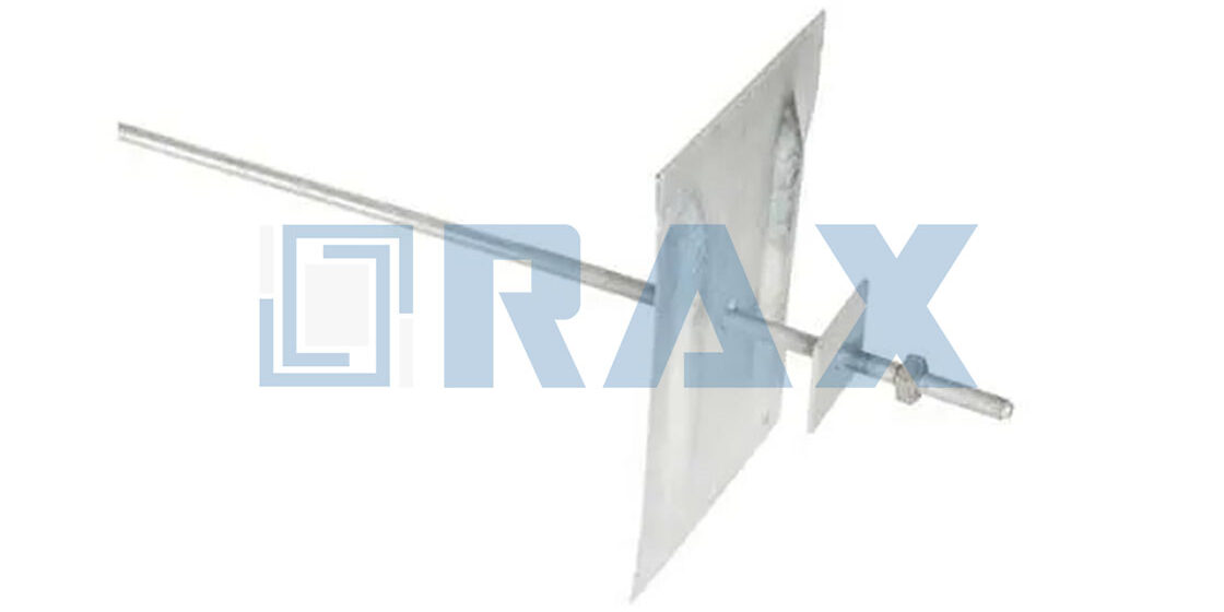
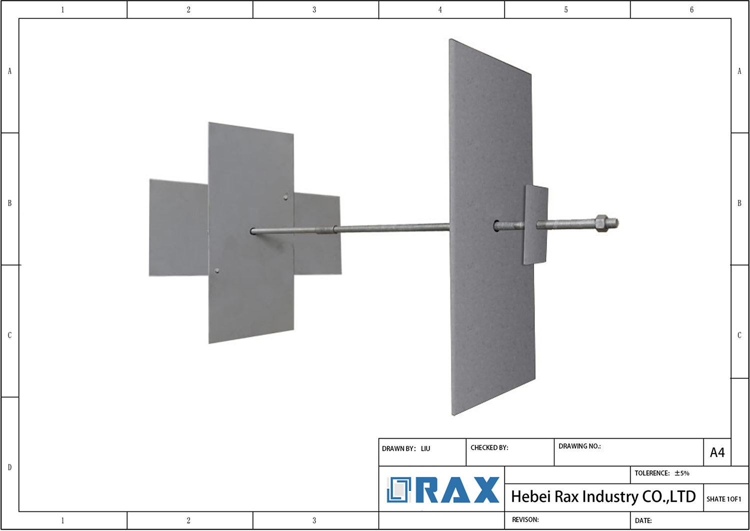
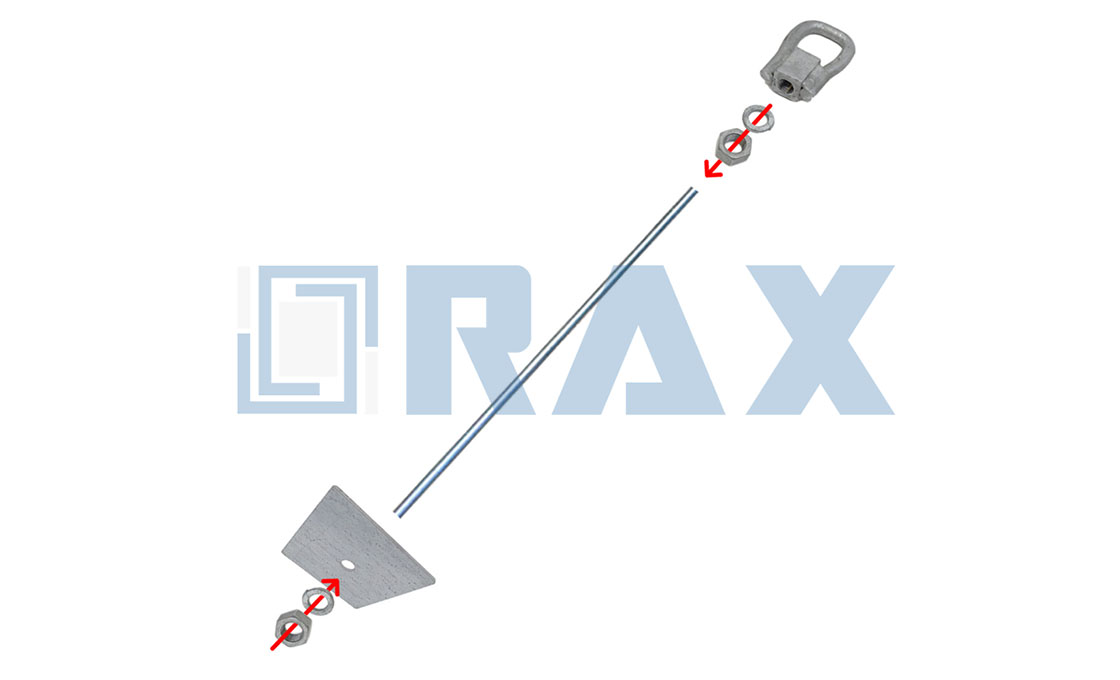
A basement wall anchor system typically consists of an interior tie plate, a steel rod, an exterior anchor plate buried in stable soil, and a coupling mechanism. The interior plate applies tension against the foundation wall while the exterior plate resists movement through the surrounding earth. Proper integration of these components ensures effective load distribution across the wall structure.
Can anchors straighten bowed walls?
Foundation wall anchors can gradually correct minor bowing by applying controlled tension over time as the soil stabilizes. The process involves tightening the rod to pull the wall back toward plumb, though significant structural deformation may require additional stabilization methods. Engineers typically monitor progress during installation to ensure the wall returns within acceptable tolerance limits.
How do carbon fiber and steel anchors compare?
Steel anchors provide higher tensile strength and are preferred for active stabilization of significantly bowed walls requiring substantial force. Carbon fiber straps are lightweight and corrosion-resistant, making them suitable for non-structural reinforcement or environments where rust prevention is paramount. The choice depends on the required load capacity, installation constraints, and long-term performance expectations.
How is water leakage prevented through anchor penetrations?
Water intrusion through anchor penetrations is prevented by installing waterproof membranes and specialized sealants around the rod exit point. Proper flashing details direct moisture away from the basement wall interface, while high-density rubber gaskets create a barrier along the rod. Engineering specifications should mandate watertight detailing to eliminate seepage risks during hydrostatic pressure events.
Do wall anchors require maintenance?
Once installed and properly tensioned, earth anchors generally require minimal maintenance due to their passive structural role. Periodic visual inspections of the interior tie plate and rod connections help detect any signs of corrosion or settlement. Most systems remain functional for the lifespan of the structure when protected against environmental degradation.