
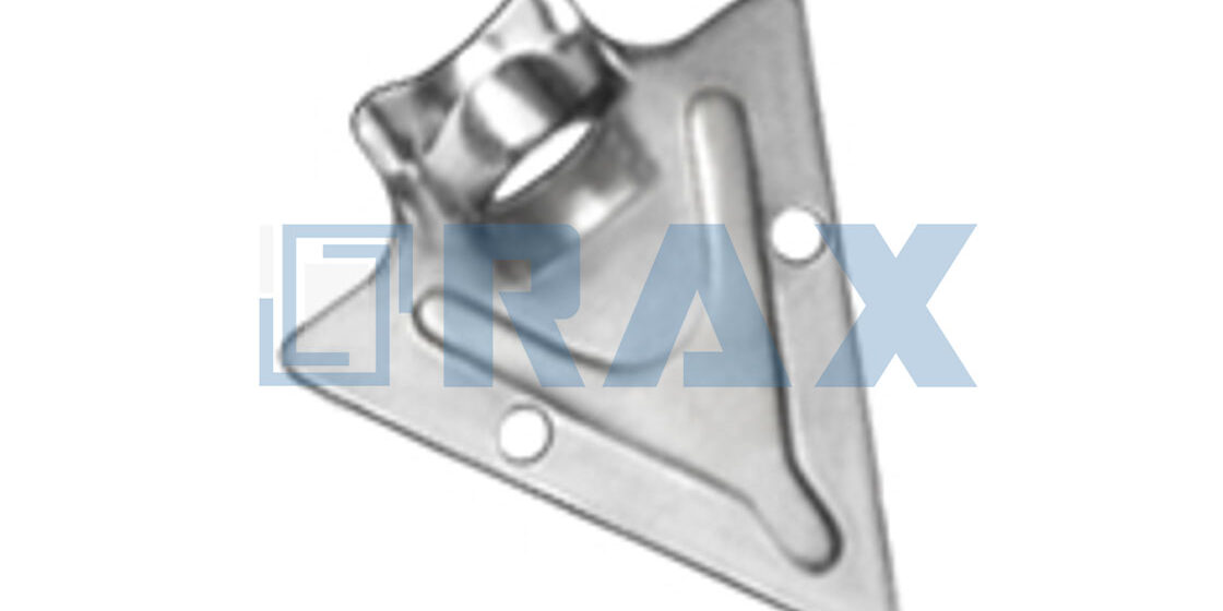
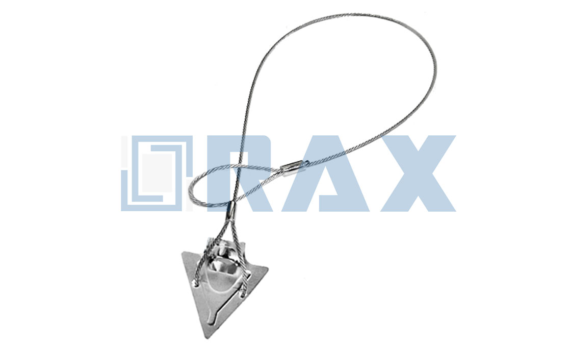
Most utility procurement failures happen because the anchor choice ignores soil density. An arrow anchor holds hard, compact, and rocky terrain where other designs pull free under line tension. We build these in the USA to ensure consistent load ratings every time they leave our facility.
This guide breaks down screw-in mechanics versus driven systems and explains how ASTM A123 galvanizing protects against grid failure. You will learn exactly how to match soil classes to anchor sizes and install them for maximum holding strength without costly rework.
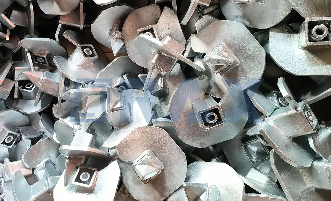
Why Arrow Anchors Outperform the Rest
Arrow anchors outperform standard driven anchors by converting installation torque into immediate soil compression, creating a dense “cone of influence” rather than a void, resulting in superior holding capacity.
Proprietary Screw-In Technology Mechanics
The fundamental advantage of the arrow anchor lies in its mechanics: it functions as a soil displacement wedge rather than a friction-based plate. Unlike driven anchors that rely on surface area and loose soil compaction, the screw-in design utilizes a helical or augered action to penetrate the ground while compressing the surrounding soil laterally. This action densifies the soil matrix immediately around the anchor shaft and head, significantly increasing the shear strength of the localized earth.
We utilize automated hot-forging to manufacture these components, ensuring the geometry of the arrowhead maintains a precise lead angle. This precision is critical; even a minor deviation in the blade angle can reduce soil compression efficiency by up to 15%. By strictly controlling the forging temperature and pressure, we eliminate the micro-fractures often found in cast alternatives, ensuring that the mechanical energy applied during installation is directly transferred to the soil rather than absorbed by structural deformities in the anchor itself.
Structural Superiority Over Driven Anchors
A common failure point in utility projects is the “rod-blade separation” found in cabled driven anchors (such as duckbill systems). These systems require a triggering mechanism to engage the blade, which introduces a variable delay between installation and load engagement. In contrast, the arrow anchor is typically a unitary structure where the rod and head are forged or welded as a single continuous load path. This configuration allows for immediate load acceptance upon installation, eliminating the “settle time” required for driven anchors to shift and lock into position.
Structurally, the rigid shaft of a screw-in anchor provides superior resistance to vertical shear forces. Driven anchors can rotate or “spin out” in loose or shifting soil because the cabled connection lacks torsional rigidity. The solid shaft of the arrow anchor acts as a stabilizer, locking the device in three dimensions. Our in-house load testing, verified per IEC standards, consistently demonstrates that forged rod anchors exhibit higher ultimate tensile strength (UTS) compared to stamped or assembled driven units, primarily due to the absence of stress risers at connection points.
Load Distribution in Extreme Environments
In extreme environments, such as the permafrost regions of Russia or the loose sedimentary soils of South America, load distribution is not just about the anchor, but about the behavior of the soil under stress. Arrow anchors distribute load through a “conical compression zone.” As tension is applied to the rod, the arrowhead pulls against a compacted column of earth directly above it. This creates a spherical bearing area that engages significantly more soil mass than the physical size of the blade.
Our experience supplying high-breaking load hardware for extreme climates has shown that screw-in anchors resist “creep” better than driven alternatives. In frozen ground, a driven anchor creates a cavity that can fill with meltwater, leading to ice jacking and subsequent failure. The screw-in action minimizes soil disturbance, preserving the thermal integrity of the surrounding permafrost. Furthermore, our double-review QC protocol ensures that the weld between the helix and the rod—critical for maintaining this load path—undergoes rigorous gauge testing to prevent detachment under the cyclic loading caused by high-wind events.
| Characteristic | Driven Anchors (Cable/Duckbill) | Arrow Anchors (Screw-In) |
|---|---|---|
| Soil Engagement | Displaces soil, creates void | Compresses soil, increases density |
| Load Activation | Delayed (requires rod retrieval/tensioning) | Immediate (direct engagement) |
| Torsional Resistance | Low (prone to spinning in loose soil) | High (rigid shaft prevents rotation) |
| Primary Failure Mode | Blade slippage or cable elongation | Soil shear (rare, if sized correctly) |
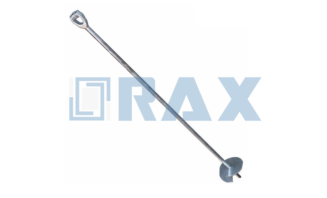
Why No-Wrench Beats Cable Drive Systems
No-wrench anchors utilize helical displacement to maintain soil density, offering superior and immediate verification of holding power compared to the disturbance-based mechanics of cable drive systems.
No-Wrench Design Holding Power Advantages
The fundamental mechanical advantage of the no-wrench design lies in its method of soil engagement. Unlike cable drive systems that rely on impact to force a cone or tip through the earth—a process that displaces soil violently and creates air pockets or “loose zones”—the no-wrench screw anchor cuts a precise thread into the substrate. This action effectively compacts the soil against the helix plates rather than pushing it aside. In cohesive soils such as dense clay or loam, this compaction significantly increases the friction between the soil and the anchor, translating directly to higher ultimate holding capacity.
additionally, the holding power of a no-wrench anchor is derived from the full surface area of the helix bearing against undisturbed soil at the installation depth. Cable drive systems often suffer from a “settling period” where the soil must re-consolidate around the displaced shaft before the anchor achieves its rated capacity. With a no-wrench system, the structure is immediately secure because the soil mechanics are optimized at the moment of installation. This eliminates the variability often seen with driven anchors where the holding power is highly dependent on the operator’s ability to drive the anchor to the exact correct depth and angle without deflecting off obstacles.
Installation Efficiency Versus Cable Drive Systems
From a logistical standpoint, the no-wrench design offers a streamlined installation profile that reduces labor time and equipment dependency. Cable drive anchors typically require heavy sledges or powered jackhammers to generate the significant impact force needed to drive the anchor to the required depth. This not only demands heavier tooling but also creates physical fatigue for the installation crew, potentially leading to inconsistent installation depth as the work progresses. In contrast, the no-wrench design utilizes a simple drive bar inserted through the anchor eye, allowing the installer to Utilize rotational force to screw the anchor into the ground.
- Tooling Simplicity: Requires only a standard drive bar or crowbar, eliminating the need for heavy hammers or hydraulic power packs common with cable drive systems.
- Speed of Deployment: In residential or constrained areas, the ability to install by hand allows for faster setup and teardown without maneuvering heavy equipment around existing infrastructure.
- Minimal Site Disturbance: The rotational installation process is quieter and causes less vibration than hammering, which is critical for installations near sensitive foundations or in compact urban environments.
Torque Application and Stability Benefits
The most distinct technical advantage of the no-wrench system is the correlation between installation torque and holding capacity. This provides a measurable quality control metric that is impossible to achieve with impact-driven cable systems. When a no-wrench anchor is installed, the resistance felt during the final rotations provides an immediate, on-site verification that the anchor has engaged competent soil and will perform as expected. If the torque is too low, the installer knows instantly that the anchor has not reached a load-bearing stratum and can drive it deeper or reposition it before the guy wire is even attached.
Stability is further enhanced by the vertical integrity of the installation. Cable drive anchors are prone to “walking” or deflecting if they encounter a root or rock during the hammering process, resulting in an anchor that is not perfectly aligned with the load. This misalignment introduces lateral shear forces that can compromise the anchor’s strength over time. The no-wrench design, however, maintains a linear, vertical path into the soil. The rotational force allows the helix to maneuver minor obstructions or cut through small roots, ensuring the anchor shaft remains true to its intended angle. This precise alignment ensures that when load is applied, the force is transferred directly to the tensile strength of the anchor and the shear strength of the soil, rather than bending the shaft at a weak point caused by deflection.
Check Load Ratings and Sizes
The ultimate failure of an anchoring system is rarely the steel itself, but rather a mismatch between the anchor’s mechanical capacity and the soil’s shear strength.
Accurate load verification is the most critical step in utility pole stabilization. Engineering failures often stem from relying on catalog “ultimate holding capacities” without applying appropriate safety factors for specific soil conditions. For high-voltage transmission or heavy-duty guy wire applications, anchors must be selected not just by weight rating, but by their ability to maintain integrity under dynamic loads in varying soil classes.
Calculating Loads and Applying Safety Factors
When specifying anchors for utility infrastructure, engineers must distinguish between the “ultimate capacity” (the point at which the anchor pulls out or the soil shears) and the “safe working load” (SWL). Industry best practices dictate a minimum safety factor of 2.0 for permanent guying, with many utility projects requiring a factor of 4.0 for critical tension loads. This calculation must account for the angle of the guy wire, which effectively multiplies the horizontal load on the anchor. For instance, a guy wire under significant tension will exert a much higher pull-out force than the vertical weight alone suggests, necessitating a rigorous review of the anchor’s proof load test results.
Never assume that a high-grade steel rating guarantees high holding power. An anchor with high-tensile steel can still fail catastrophically if the helix configuration is undersized for the soil density, turning the anchor into a “bullet” that pulls out smoothly under load.
Critical Dimensional Standards for Procurement
To ensure consistent performance and resist deformation during installation and operation, specific physical tolerances must be enforced during procurement. General-purpose hardware often lacks the structural robustness required for utility grade anchoring. Buyers should strictly verify the following geometric specifications to avoid procurement of light-duty imitations that cannot withstand the torque required for no-wrench installation.
- Rod Diameter: A minimum rod diameter of 3/4 inch is essential for standard utility guy anchors. Smaller diameters may exhibit excessive elasticity or bending under lateral loads, compromising the guy wire’s tension integrity.
- Overall Length: Standard effective lengths typically start at 66 inches. This depth ensures the helix plate engages deeper, more compacted soil strata, bypassing the loose surface layers that offer negligible holding power.
- Helix Thickness: The helix blade must maintain a structural thickness of at least 1/4 inch. Thinner blades are prone to warping or “cupping” when torque is applied during the screw-in process, which drastically reduces the bearing surface area and ultimate load capacity.
Soil Class and Rated Capacity Variance
A single anchor model will exhibit drastically different load ratings depending on the soil classification. A rated capacity in Soil Class 5 (very soft, loose, or marshy soil) will be a fraction of its capacity in Class 2 (dense gravel or sand). When reviewing technical data sheets, buyers must verify if the stated load rating is an “ultimate” rating or a “rated” capacity based on a specific soil type.
For example, in Class 5 soil conditions, standard arrowhead anchors may require a significantly larger helix blade or multiple anchors to achieve the same holding power achieved by a single anchor in stable loam. Procurement specifications should mandate that suppliers provide load de-rating curves for Soil Class 4 and 5 environments to ensure the project’s safety margins are maintained even in sub-optimal ground conditions.
| Feature | Specification | Advantage |
|---|---|---|
| Galvanizing Standard | ISO 1461 / ASTM A153 (>85μm mean coating) | Superior rust protection and corrosion resistance |
| Manufacturing Process | Automated Hot-Forging | Enhanced structural integrity and precision over casting |
| Quality Control Protocol | 100% Double-Review by 10-Person QC Team | Guaranteed dimensional accuracy and defect-free delivery |
| Testing Compliance | In-house Load Testing per IEC 120 | Verified performance under rigorous operational stress |
| Certification Status | SGS Verified & Tested | Global market acceptance and trust assurance |

How Arrow Anchors Connect to Hardware
Verifying Fitment with Triple-Eye Forged Rods
The reliability of a guyed pole infrastructure is determined at the connection interface. Because arrow anchors generate massive tensile loads, standard hardware connections are often insufficient. The industry-standard solution involves verifying fitment with triple-eye forged rods and standard hardware interfaces to prevent critical connection failures during assembly.
Triple-eye forged rods feature three distinct connection points: one eye for the anchor shank, one for the guy wire, and a central hole for a pin or bolt securing the hardware. This robust configuration ensures that tension is distributed evenly across the system. When a guy wire fails due to loose connections or rod deformation, the entire utility pole can suffer catastrophic structural compromise.
- Forged vs. Cast Steel: Ensure all connection hardware uses forged steel components. Casting methods introduce internal voids that fail under high dynamic loads, whereas forging aligns the metal grain structure for maximum tensile strength.
- Precision Tolerances: The holes in the triple-eye rod must have strict dimensional tolerances (typically within 1mm) to ensure the securing bolts fit snugly. Loose tolerances lead to mechanical play, which causes accelerated wear and premature fatigue failure.
- Galvanizing Integrity: Check that the hot-dip galvanizing process does not overspray or clog the threaded ends and eye holes. A mean coating thickness exceeding 85 microns is standard, but engineers must verify that clearance fits remain intact post-coating.
Choose the Right Anchor for Your Soil
Matching Anchor Geometry to Soil Stratigraphy
Selecting the correct anchor geometry is not a matter of preference, but of geological necessity. When you attempt to install a standard driven rod in clay-heavy or rocky terrain, the soil’s shear resistance can cause the anchor to deflect, skip, or fail to penetrate entirely. Conversely, using a screw-in helical design in soft, sandy loam can be over-engineered and inefficient. The key to optimizing structural stability lies in matching the installation mechanics to the ground composition.
For unstable, high-water-table, or soft soils, torque-driven helical anchors are the industry standard. By screwing into the ground rather than displacing it, they create a continuous bearing surface that resists lateral pullout forces far more effectively than static driven piles. This makes them the safest choice for power lines spanning marshlands or loose riverbanks where traditional driving would result in catastrophic slippage.
In normal to compact soils, cross-plate anchors are generally preferred. These utilize a driven rod with a perpendicular plate to maximize surface area against dense earth. While highly effective for general utility poles, attempting to screw these into rocky or cavity-prone ground is risky, as the vibration from driving can dislodge loose rock and compromise the grip. In such difficult terrain, expanding anchors that mechanically lock into cavities provide superior holding power.
Screw-In Mechanics vs. Driving Torque
The installation method dictates the holding capacity. No-wrench screw anchors offer a distinct advantage in sandy or loamy soils due to their toggle-action design, which integrates the drive mechanism directly into the anchor body. This eliminates the need for separate heavy machinery, allowing for rapid deployment by a two-person crew while maintaining structural integrity that often exceeds cast alternatives.
However, it is vital to understand that holding strength is not just about the anchor itself—it is about how the tool transfers force into the ground. If your team is unaccustomed to torque-driven installation, the learning curve can lead to under-tightening, which dramatically reduces the anchor’s efficacy. We always recommend that field crews undergo specific training on torque application to ensure the anchor reaches its full rated capacity.
- Utility Pole Guy Anchors: Typically require deep penetration into stable soil layers; usually paired with helical or cross-plate designs.
- Solar Foundation Anchors: Often face variable ground conditions; hot-dip galvanizing (exceeding 85 microns) is non-negotiable for long-term corrosion resistance.
- Tension Clamps & Dead-Ends: Must be paired with an anchor that matches their break-load rating to prevent system failure during extreme weather.
| Anchor Type | Optimal Soil Conditions | Installation Method | Rax Manufacturing Advantage |
|---|---|---|---|
| Helical Anchor (Round/Square) | Unstable, Soft, or High Water Table Soils | Torque-Driven Screw-In | Hot-forged for superior strength; ISO 1461 galvanizing (>85 microns) |
| Cross-Plate Anchor | Normal to Compact Soils | Driven Rod with Perpendicular Plate | Automated high-precision production; 100% double-review QC |
| Expanding Anchor | Rocky or Cavity-Prone Ground | Driven with Tip Expansion | Custom OEM/ODM mold capabilities; SGS verified |
| No-Wrench Screw Anchor | Sandy or Loamy Soils | Drive-in with Toggle Action | Superior integrity over casting; In-house IEC 120 load testing |

Why ASTM Galvanizing Guarantees Quality
ASTM Galvanizing Guarantees Quality Through Adhesion and Thickness
In the utility infrastructure sector, galvanizing is not merely a cosmetic finish but the primary defense against catastrophic structural failure. For steel cross arms, guy clamps, and earth anchors, ASTM A153 (for small hardware) or ASTM A123 (for structural steel) specifications are the non-negotiable industry standard that guarantees long-term durability. Relying on zinc-rich paints or inferior pre-galvanized materials often leads to rapid delamination in corrosive environments, leaving the base metal vulnerable to the elements.
Executive Insight: True quality in pole line hardware is defined by metallurgical bonding, not just surface application. The ISO 1461 standard for hot-dip galvanizing ensures the zinc forms an integral part of the steel itself.
The Metallurgical Advantage of Hot-Dip Processes
The mechanism behind why ASTM galvanizing works is chemical. During the hot-dip process, steel is cleaned and fluxed before being submerged in molten zinc at approximately 840°F (449°C). This triggers a metallurgical reaction where iron and zinc combine to form a series of zinc-iron alloy layers. These layers are metallurgically bonded to the steel substrate, meaning the coating cannot chip, peel, or flake under physical impact—a common failure point for mechanically applied coatings.
- Complete Coverage: Unlike spray-on alternatives, the liquid zinc flows into every nook and cranny, providing full encapsulation of complex geometries like double-arming bolts and guy grips.
- Self-Healing Properties: Zinc acts as a sacrificial anode. If the coating is scratched down to the bare steel during installation, the surrounding zinc corrodes preferentially, protecting the exposed area from rust.
- Thickness Uniformity: Standardized immersion ensures a consistent coating thickness across the entire component, preventing thin spots that serve as weak points for corrosion.
Decoding the Specifications: Thickness and Durability
When evaluating suppliers, B2B buyers must look for specific adherence to mean coating thickness standards, typically measured in microns. High-tier industrial standards demand a minimum mean coating weight that translates to robust protection.
📋 Key Quality Benchmarks
- ISO 1461 Compliance: Leading manufacturers ensure their galvanizing processes exceed standard requirements, maintaining a mean coating thickness exceeding 85 microns for heavy-duty hardware.
- Surface Finish: A smooth, bright, and uniform finish indicates proper fluxing and temperature control, ensuring maximum adhesion and resistance to environmental stress.
- Traceability: Qualified suppliers provide mill test reports and SGS certification verifying that the galvanizing bath chemistry and coating weights meet the exact ASTM requirements specified in the tender.
Vetting for Factory Traceability
The “guarantee” of quality relies heavily on factory traceability. A manufacturer’s commitment to quality is verified by a rigorous internal protocol where a dedicated QC team monitors every production stage. A robust “double-review” process ensures that 100% of products—whether ADSS suspension clamps or helical anchors—are inspected twice for coating integrity before packaging.
How You Install Affects Holding Strength
The Installation Method Drives Structural Integrity
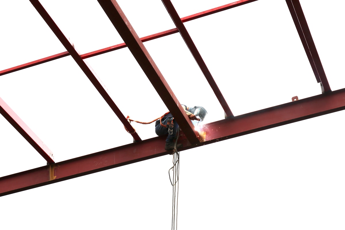
The theoretical load-bearing capacity of an arrowhead earth anchor is meaningless if the installation process fails to achieve optimal soil engagement. Holding strength is not merely a function of the anchor’s weight or material grade; it is a direct variable of the mechanical force applied during deployment. Field data indicates that deviations from strict torque protocols can reduce actual structural capacity by up to 40%. This performance gap is why professional power installation techniques are mandatory for utility grid safety and long-term infrastructure stability.
Incorrect deployment methods, such as excessive rotation speed or insufficient vertical alignment, compromise the helix-to-soil interface. In granular soils, rapid installation prevents proper particle displacement, leading to reduced friction. In cohesive clays, misalignment creates void spaces around the shaft. These structural defects create weak points where lateral loads—common in pole line hardware applications—will initiate failure. The anchor must be seated at a precise angle and depth to distribute stress evenly across the helical blades.
Achieving Full Capacity Through Professional Standards
To ensure every unit performs to its rated maximum, contractors must adhere to rigorous installation benchmarks. We strictly recommend verifying penetration depth against manufacturer specifications, as even minor under-driving reduces the effective surface area available for load transfer. Furthermore, consistent torque application is critical; our engineering teams observe that proper torque values compress the surrounding soil, significantly increasing the frictional resistance that holds the anchor in place.
- Vertical Alignment: Maintain a plumb line during screwing to prevent bending the drive rod or damaging the helix geometry.
- Calibrated Torque: Use torque wrenches calibrated to the specific anchor model’s requirements to avoid over-stressing the hot-forged steel or under-compacting the soil.
- Depth Verification: Measure penetration relative to the ground surface to confirm the helix blades have fully engaged the target load-bearing soil stratum.
Professional Power Installation Best Practices
Professional installation goes beyond simple screwing. It requires a systematic approach that accounts for real-time site conditions. For expansive clay or loose sandy soils common in diverse regional climates, increasing the penetration depth by an additional 10% to 15% beyond standard guidelines compensates for lower soil cohesion and ensures stable anchoring. This slight adjustment acts as a critical safety buffer against shifting ground masses.
Additionally, the choice of driving equipment matters. Hydraulic drivers offer consistent rotational force, whereas manual or pneumatic tools can introduce variable stress. Inconsistent force application leads to uneven thread engagement, which is a primary cause of premature anchor pull-out. By prioritizing controlled, steady installation methods, utility professionals guarantee that the high-breaking loads designed into Rax Power’s hot-forged anchors are fully realized in the field.
How Galvanizing Protects Against Corrosion
Corrosion is the primary failure mode for earth anchors. A robust hot-dip galvanizing process, specifically one exceeding 85 microns and adhering to ISO 1461, is non-negotiable for protecting the critical helix-to-rod weld joint.
Certified Galvanizing Process for Corrosion Protection
The single greatest threat to the longevity of any steel earth anchor is oxidation. While the rod and helix are designed to bear significant mechanical loads, exposure to soil chemicals, moisture, and varying pH levels can rapidly degrade structural steel. To counter this, the industry relies on hot-dip galvanizing (HDG), a metallurgical process where iron and zinc react to form a series of zinc-iron alloy layers. This is not merely a paint coating; it is a chemical bond that provides sacrificial protection. Even if the underlying steel is exposed due to abrasion during installation, the surrounding zinc will corrode preferentially to protect the steel.
However, the efficacy of this protection is entirely dependent on the quality of the galvanizing bath and the pre-treatment process. In our manufacturing experience, we have found that strict control over the bath temperature and immersion time is critical to prevent “white rust” (zinc oxidation) or flaking, which are common defects in lower-cost manufacturing that compromise the anchor’s service life.
Helix-to-Rod Weld Integrity Maintenance
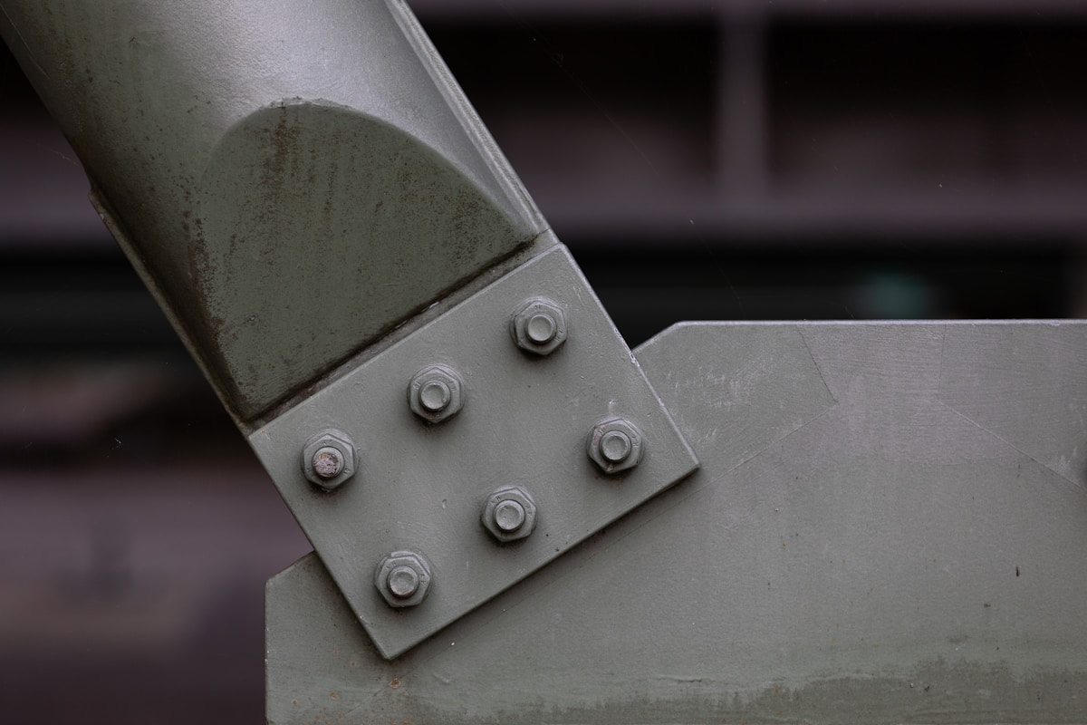
The helix-to-rod weld is the Achilles’ heel of any screw anchor. This junction bears the full brunt of the torsional torque during installation and the tensile load during operation. If the galvanizing layer is inconsistent or thin at the weld point, this area becomes the epicenter for corrosion-induced failure. Welding alters the metallurgical structure of the steel, often making it more susceptible to rust if the galvanizing does not properly flow over and penetrate the weld bead.
Inspectors frequently ignore the weld area, assuming the zinc coating is uniform. A failure here usually results in the helix detaching from the rod under load, causing catastrophic system collapse.
To mitigate this, our production line utilizes a hot-dip process specifically optimized to ensure the zinc fluidity fully encapsulates the weld geometry. We enforce a rigorous standard where no bare spots or “masked” areas are tolerated on the weld seam. This is verified through a double-review protocol where the weld integrity is scrutinized both before and after the galvanizing process.
ISO 1461 Compliance and Coating Thickness
For B2B buyers and utility engineers, “galvanized” is too vague a term. The only measurable assurance of corrosion resistance is adherence to specific standards like ISO 1461. This standard defines the minimum coating thickness based on the steel’s thickness and categorizes the finish quality. Compliance ensures that the anchor will perform reliably in the ground for decades, rather than failing within a few years due to rust bleed.
While many competitors meet the bare minimum of the standard, our internal specifications demand a more robust defense. We strictly adhere to a mean coating thickness exceeding 85 microns. This substantial layer acts as a long-term reservoir of sacrificial metal, ensuring that even in aggressive soil conditions, the anchor remains protected. Our finished products also feature a smooth, bright finish, which not only meets aesthetic requirements but also indicates a clean, high-quality galvanizing bath free from excessive dross or ash.
- ISO 1461 Compliance: Mandatory for all pole line hardware to ensure uniform coating distribution and adhesion.
- Mean Coating Thickness: We guarantee a minimum of 85 microns, significantly buffering against soil abrasion.
- Verification: 100% of our batch production is SGS verified to ensure these metrics are consistently met.
Conclusion
Selecting the right arrowhead earth anchor requires matching soil class ratings to specific load requirements. ASTM A123 galvanizing ensures long-term corrosion resistance in harsh environments. Our engineering team manages production for certified screw-in anchors that deliver consistent holding power across diverse project specs.
- Confirm soil classification and required pullout loads before ordering.
- Contact our technical support for design guidance without commercial obligation.
Frequently Asked Questions
How is the strength of an arrow anchor calculated?
Anchor strength is determined by soil shear resistance, anchor geometry, and the angle of installation relative to the load. Engineers use formulas incorporating soil cohesion and internal friction angles to estimate ultimate pullout capacity. Safety factors are applied to derive the allowable working load for design purposes.
What maintenance do arrow anchors require?
While often considered permanent, periodic inspection of anchor heads and connected hardware is recommended to detect corrosion or loosening. In aggressive environments, checking galvanization integrity and tension levels helps identify potential degradation early. Routine monitoring prevents unexpected failures in critical support structures.
Are testing certifications available for arrow anchors?
Reputable manufacturers provide comprehensive test reports, including SGS verification and in-house load testing per IEC 120 standards. These documents validate mechanical properties and coating thickness, ensuring compliance with international utility requirements. Buyers should request these reports to verify product performance before procurement.
Can custom molds be developed for specific arrow anchor designs?
OEM capabilities allow for custom mold development to transform specific drawings or concepts into finished hardware solutions. This process enables precise adaptation to unique project requirements, such as non-standard dimensions or specialized attachment points. Customization supports tailored engineering needs without compromising manufacturing efficiency.
What quality standards apply to arrow anchors in South America?
Regional utilities often demand high-tier quality standards, focusing on dimensional accuracy and material consistency for grid infrastructure. Manufacturers must adhere to strict tolerance levels, such as 1mm precision for steel cross arms, to ensure compatibility. Compliance with local tender requirements is essential for successful market entry.