
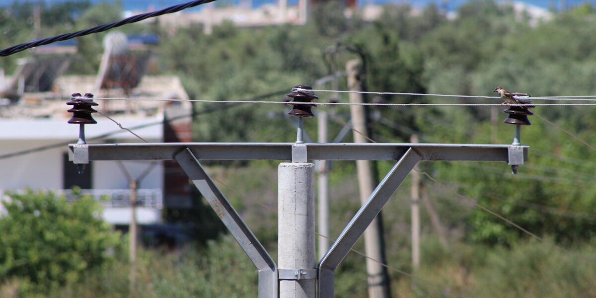
Vibration fatigue and clamp slippage turn a conductor span into a multi-day crew mobilization when strands separate. Most failure reports trace back to one variable. The hardware between the clamp and the conductor lacks the right grip geometry. An armor rod solves this. It wraps a helically formed sleeve around the conductor at suspension and dead-end points, restoring mechanical continuity where bending stresses concentrate. Preformed designs deliver no less than 95% of the parent conductor’s tensile strength. That’s the benchmark utility specs require for high-voltage overhead lines.
This guide covers the specifications that actually determine whether an armor rod performs or fails in the field. Material grades that resist galvanic corrosion with ACSR and AAAC conductors. Helix pitch calculations tuned to wind vibration frequencies. Placement zones defined by ANSI and IEC load testing protocols. You’ll know which parameters to verify on supplier certifications before accepting delivery. Pass commissioning audits on the first attempt.
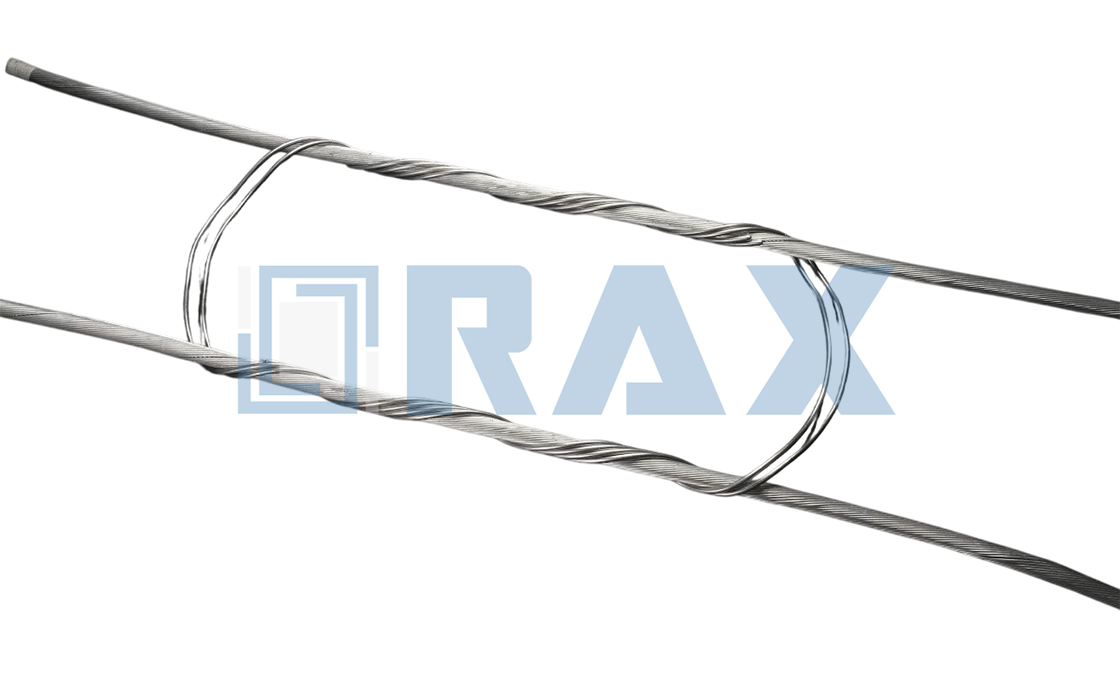
The Materials and Dimensions That Shape Rod Strength
Armor rod performance depends on metallurgical consistency, precise helical geometry, and verified coating integrity—not vague supplier claims.
Aluminum Alloy Grade and Tensile Ratings
The alloy grade determines how the rod behaves when it transfers mechanical load from a suspension clamp back into the conductor strands. Generic aluminum wraps often lack consistent temper, which leads to uneven hardness across the helical surface. When the temper varies, certain sections deform under clamp pressure while others remain too soft to provide meaningful abrasion resistance.
We specify controlled alloy tempering that delivers predictable tensile behavior across every production batch. This consistency ensures the rod grips the conductor firmly without exceeding the mechanical limits of the stranded wire. Procurement teams should request documented tensile ratings rather than relying on material descriptions like “aluminum alloy” without grade verification.
Wire Diameter and Helix Pitch Specifications
Wire gauge and lay length work together to define the protective envelope around the conductor. If the wire diameter fluctuates during extrusion or drawing, the resulting helix becomes irregular, creating high-pressure spots that can indent soft aluminum strands. Consistent wire sizing guarantees that contact pressure distributes evenly along the entire wrap length.
The helix pitch controls how tightly the preformed layers interlock and how well the rod recovers its shape after installation. Precision forming equipment maintains tight pitch control, preventing the wrap from relaxing under thermal expansion or vibrating loose over time. In our production environment, we verify pitch stability against the conductor profile before releasing any batch, because out-of-spec lay lengths compromise both mechanical protection and long-term field reliability.
Hot-Dip Coating Thickness Ensures Corrosion Resistance
For galvanized steel wire components, corrosion resistance is governed by the metallurgical bond formed during the hot-dip process, not merely the visible surface finish. A proper zinc-iron alloy layer penetrates the steel surface, creating a barrier that survives mechanical handling, transport, and field assembly. Thin or poorly bonded coatings chip easily, exposing the base metal to rapid oxidation at stress points.
Industry buyers should treat coating thickness as a non-negotiable procurement requirement backed by mill certificates. We require documented proof of coating weight and finish verification on every lot, ensuring the hardware performs consistently in wet, saline, or industrial atmospheric conditions without relying on visual inspection alone.
Dimensional Tolerance Impact on Conductor Grip
Tolerance control is the difference between a rod that protects a conductor and one that damages it. An oversized wrap creates clearance gaps where moisture and debris can accumulate, while an undersized wrap squeezes the strands and alters the conductor’s effective diameter. Both outcomes reduce the service life of the transmission line and increase failure risk at suspension points.
We hold strict dimensional tolerances through precision-controlled forming and sequential measurement checks throughout manufacturing. A dedicated quality control team inspects every component twice before packaging, catching deviations that would otherwise reach the job site. This disciplined approach eliminates field fitment issues, reduces rework costs, and ensures that each rod matches the conductor envelope exactly as engineered.
| Rod Parameter | Material & Dimension Spec | Strength & Protection Benefit | Compliance & Testing |
|---|---|---|---|
| Base Material Composition | Aluminum Alloy or Galvanized Steel Wire | Matches conductor metallurgy to prevent galvanic corrosion while resisting abrasion, bending fatigue, and dynamic vibration | Conductor-specific compatibility verified for ACSR, AAAC, and ACSS applications |
| Diameter Tolerance | ±1mm Precision Sizing | Guarantees a snug helical wrap that prevents strand deformation or clearance slippage at suspension points | Automated machining and gauge verification per production QC protocol |
| Helical Layer Configuration | Single or Double-Layer Preformed Wrap | Preformed armor wraps protect conductors by distributing mechanical load evenly across the strand surface without relying on specialized termination geometries. | Helical preform geometry and lay direction verified per production QC protocol |
| Surface Protection Coating | Hot-Dip Galvanizing Exceeding 85μm | Delivers superior corrosion resistance for extreme wind, ice loading, and coastal industrial environments | ISO 1461 and ASTM A153 compliant with smooth, bright finish verification |
| Mechanical Load Rating | IEC 120 Documented Tensile & Holding Capacity | Provides documented grip tensile and holding capacity data to prevent line failure under peak utility loads | In-house IEC 120 load testing and SGS third-party verification |
How the Wrap Transfers Stress Away from Strands
Helical Geometry and Friction Distribution
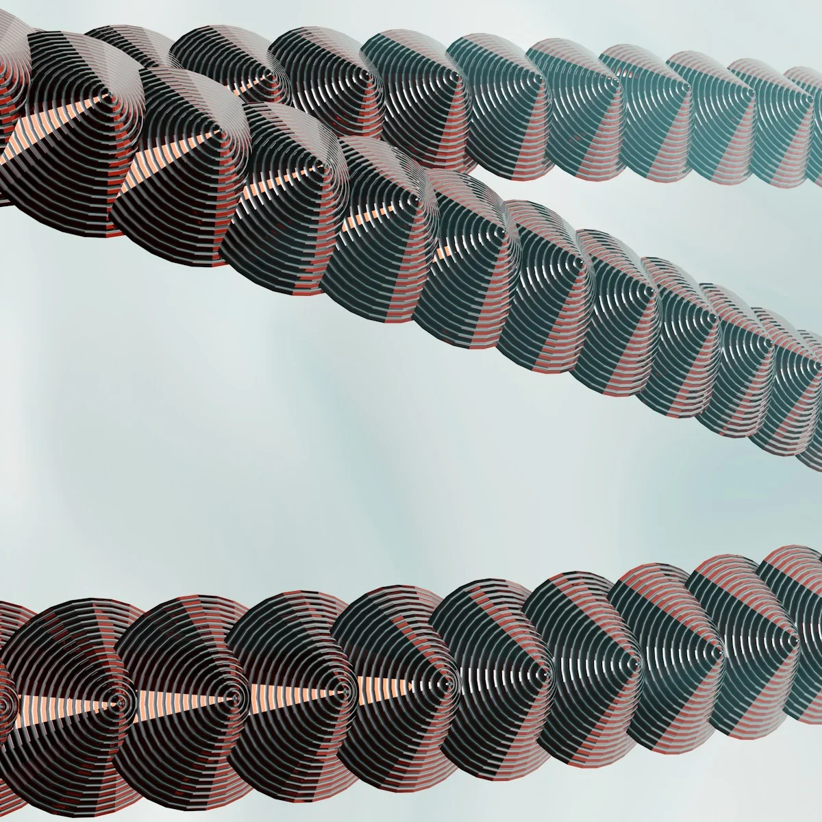
The protective capability of an armor rod is fundamentally rooted in its helical geometry, which is engineered to match the lay length and diameter of the conductor. Unlike a mechanical clamp that relies on point-loading bolts to secure a line, a preformed rod utilizes the surface area of its spiral shape to generate grip. When installed, the rods wrap tightly around the conductor, creating a high-friction interface over an extended length rather than a single inch or two. This geometry converts the radial clamping force—exerted by the rod’s elastic memory—into a distributed holding pressure. Because the contact area is maximized, the friction force resisting slippage is significantly higher, ensuring that the rod does not shift under dynamic loads while simultaneously cushioning the conductor against the hard edges of suspension hardware.
Load Sharing Across Individual Conductor Strands
In multi-strand conductors such as ACSR or AAAC, uneven loading is a primary cause of fatigue failure. Without an interface, a suspension clamp typically bears down only on the topmost strands, leaving lower strands underutilized and creating high shear stress at the edges of the clamp. A preformed wrap acts as a stress-equalizing sleeve that binds the strands together. By enclosing the entire conductor bundle, the armor rod forces the assembly to behave more like a solid, homogeneous unit. This mechanism transfers the tensile load from the clamp directly to the core and inner strands, engaging the full cross-sectional area of the conductor. Consequently, the bending stiffness is uniform, preventing the outer strands from carrying a disproportionate share of the mechanical burden during Aeolian vibration or wind-induced galloping.
Preformed Design Eliminates Localized Strand Abrasion
One of the most critical advantages of the preformed design is the elimination of “fretting” or localized abrasion. Traditional bolted solutions or field-formed wires can create pressure points that cut into the aluminum strands, leading to micro-cracks that propagate over time. Preformed rods are manufactured with a specific set radius that matches the conductor’s neutral axis. When applied, the rod maintains a constant pressure without cutting into the metal. This interface dampens the relative movement between the strands and the suspension assembly. By preventing metal-to-metal rubbing at the suspension point, the design effectively mitigates wear caused by steady-state vibration, preserving the conductor’s tensile strength and electrical conductivity over its operational lifespan.
Tapered Termination Zones for Stress Dispersion
The most vulnerable point in any reinforcement system is the transition zone where the protection ends and the bare conductor begins. To address this, quality armor rods feature tapered termination zones where the grip gradually relaxes. In these terminal sections, the helical pitch may be altered, or the diameter of the last few coils may be reduced. This taper ensures a smooth transition of bending stiffness from the rigid, reinforced section to the flexible, free-span section of the conductor. Without this gradient, a sharp “step” in stiffness would create a stress concentration point at the rod’s end, effectively moving the failure point just outside the protection area. The tapered geometry disperses these bending stresses over a broader distance, ensuring that the conductor is not subjected to a localized bending moment that exceeds its fatigue endurance limit.
How to Verify the Rod Fits Your Conductor
Matching Inner Diameter to Conductor Outer Dimensions
The most common procurement error is assuming all conductors within a nominal size class share identical outer diameters. Stranded aluminum and compacted profiles vary significantly based on manufacturing tolerances and stranding lay lengths. When an armor rod is forced onto a conductor with a larger actual diameter than its rated inner diameter, the helical wrap compresses the strands inward. This localized deformation reduces the effective cross-sectional area and introduces stress concentration points that accelerate fatigue failure.
Conversely, selecting a rod with an inner diameter that exceeds the conductor’s outer dimension creates clearance gaps between the preformed wrap and the strand surface. These gaps allow micro-movement under aeolian vibration. Instead of dampening oscillation, the rod amplifies wear at contact points and fails to distribute bending stress across the full conductor circumference.
- Precise Measurement: Measure the conductor outer diameter at multiple points before specifying the armor rod. Compacted conductors often require different sizing than standard stranded equivalents.
- Profile Sensitivity: Round conductors and compacted round or elliptical profiles demand distinct rod geometries. Substituting one for the other compromises the protective envelope.
Verifying Compatibility Across Conductor Types
Armor rod specifications must align with the specific conductor construction. Preformed line products are engineered for distinct metallic compositions and structural geometries. Standard armor rods are suitable for use on ACSR, Compacted ACSR, Aluminum Alloy All-Aluminum, AWAC Compacted All-Aluminum, ACAR, ACSS/AW, and ACSS/TW conductors. Each of these material systems interacts differently with the rod’s inner surface, requiring verified dimensional compatibility.
Installation method also dictates compatibility. Armor rods may be tapped over aluminum-based conductors, but this technique is strictly prohibited on Alumoweld or steel ground wires. Tapping over incompatible metallic structures can fracture the strand matrix or cause galvanic interaction issues. Where tapping is required, the conductor surface must be thoroughly wire brushed and an oxide inhibitor applied to prevent corrosion initiation at the contact interface.
Always request the conductor manufacturer’s published outer diameter table rather than relying solely on nominal kcmil ratings. Nominal sizes frequently mask actual dimensional variances that directly impact armor rod seating.
Field Inspection Protocol for Rod Fit
Verification does not end at procurement. During installation, the rod must exhibit uniform helical engagement along the entire wrapped length. Visual inspection should confirm zero lift-off at termination zones and consistent pressure across all contacting strands. Any visible radial separation indicates the rod was undersized for the conductor or that the conductor profile deviated from specification.
For damaged conductors where repair armor rods are deployed, the fit verification serves a dual purpose: restoring mechanical strength and re-establishing electrical conductivity. Repair rods are designed to reinstate up to 100% strength and conductivity when conductor damage remains below 7% of the square space. Confirming the correct inner diameter alignment is the only way to guarantee this restoration threshold is met.
Frequently Asked Questions
Why are armor rods incompatible with steel ground wires?
Steel ground wires have different structural rigidity and surface properties compared to aluminum or aluminum alloy conductors. Armor rod wraps designed for metallic flexibility cannot properly conform to steel wire geometry, leading to inadequate grip and potential strand damage during installation or operation.
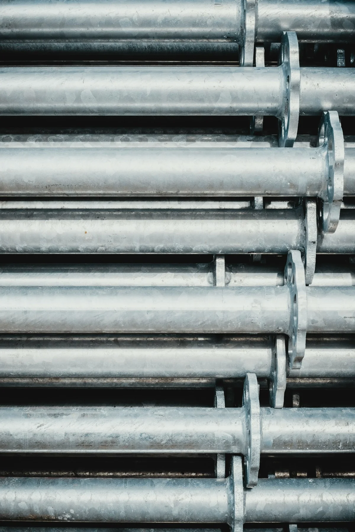
Pick Alloys for Coastal, Industrial, or Wet Sites
Coastal chlorides, industrial SO₂, and constant moisture demand higher minimum coating weights and compatible alloy selection—standard outdoor grades fail prematurely in these environments.
Coastal Deployments: Chloride Exposure
Salt spray accelerates zinc consumption in hot-dip galvanized coatings and promotes pitting on exposed steel substrates. For marine-adjacent or island-grid installations, specification must target the highest corrosion-resistance tier available for pole-line hardware.
- Recommended coating standard: ISO 1461 hot-dip galvanizing with a mean coating thickness exceeding 85 microns, verified by independent measurement rather than visual inspection alone.
- Phase conductor armor rods: Specify aluminum alloy construction to avoid dissimilar-metal corrosion where the rod contacts aluminum conductors.
- Overhead ground wires and OPGW hardware: Aluminum-clad steel provides the necessary conductivity while maintaining structural grip integrity under chloride exposure.
- Marine classification alignment: Match components to ISO 12944 C5-M atmospheric categories when the installation sits within 1–3 km of the coastline or operates in tidal splash zones.
Industrial Atmospheres: Chemical Pollutant Exposure
Utility corridors running through chemical plants, cement facilities, paper mills, or heavy refining zones face sulfur dioxide, ammonia, and acidic particulate deposition. These atmospheres behave similarly to coastal conditions in corrosion testing but often attack coating interfaces faster due to lower pH condensation.
- Minimum coating mass: Specify hot-dip galvanized finishes that exceed local utility tender requirements by one grade when the site is classified as severe industrial.
- Alloy compatibility: Ensure preformed line products and armor rods use aluminum-alloy or aluminum-clad-steel compositions that resist galvanic coupling with polluted moisture films.
- Thread protection: Double-arming bolts, eye bolts, and U-bolts installed in industrial zones require full-thread galvanizing coverage, not partial dip finishes.
- Tender documentation: Procurement teams should request SGS test reports and batch-specific coating thickness certificates for every delivery lot.
High-Moisture and Tropical Environments
Continuous humidity, heavy rainfall, and tropical heat create persistent electrolyte films on metal surfaces. Even without salt spray or industrial chemicals, moisture alone shortens service life when coating porosity or surface preparation is inadequate.
- Surface preparation requirement: Steel components must undergo proper derusting and pickling before galvanizing to ensure metallurgical bond between the zinc layer and the base metal.
- Finish quality check: Accept only smooth, bright galvanized surfaces without bare spots, flux residue, or rough spattering that traps moisture.
- Component selection: Helical and expanding earth anchors used in waterlogged soil should carry the same hot-dip specification as overhead hardware to prevent underground-to-overground corrosion transfer.
- Storage protocol: Bulk shipments destined for tropical deployment must remain wrapped in moisture-barrier packaging until installation day.
Coating Selection Matrix for Harsh Sites
Procurement teams often default to the cheapest available galvanizing option, then replace failed hardware three to five years later. A side-by-side specification matrix removes guesswork and aligns material selection with actual site conditions.
- Standard rural outdoor: Commercial hot-dip galvanizing per ASTM A153 or ISO 1461 meets baseline requirements; suitable for low-pollution, dry climates.
- Coastal or marine: Minimum 85-micron mean thickness per ISO 1461, C5-M atmospheric classification, aluminum-alloy rod bodies for phase conductors.
- Industrial severe: Enhanced coating mass above standard tender minimums, full-thread coverage on all fasteners, SGS-certified batch documentation required.
- Tropical high-moisture: Prioritize surface preparation quality and absence of porosity; combine hot-dip finish with sealed packaging logistics.
Frequently Asked Questions
Can standard galvanized armor rods survive near-sea installations?
Short-term, yes. Long-term, rarely. Standard commercial galvanizing lacks the coating mass needed to sustain service life under continuous chloride exposure. Utilities deploying within coastal zones should specify enhanced hot-dip finishes from the outset rather than planning replacement cycles.
Is aluminum-clad steel always better than plain steel for ground wires in corrosive sites?
For overhead ground wires and OPGW hardware, aluminum-clad steel provides superior corrosion resistance while maintaining electrical continuity. Plain steel components rely entirely on coating integrity and will degrade faster if the zinc layer is breached during handling or installation.
How do buyers verify coating thickness on bulk deliveries?
Request mill test reports tied to production batch numbers, and conduct random magnetic-induction gauge measurements on incoming shipments. Reject lots showing localized readings below the specified mean thickness, especially on threaded fasteners and anchor components.
How to Tune Helix Pitch for Wind Vibration
Matching helix pitch to expected aeolian vibration frequencies prevents suspension-point fatigue. Correct pitch balances radial grip tension against allowable conductor micro-movement, ensuring the rod dissipates vibrational energy instead of concentrating stress at the clamp exit.
Procurement teams frequently specify preformed armor rods by nominal conductor diameter alone. This approach treats the rod as a static sleeve rather than a dynamic vibration control component. In exposed overhead spans, conductors experience aeolian vibration across a broad frequency spectrum, typically ranging from 3 Hz to 100 Hz depending on wind speed, span length, and conductor mass. The helix pitch directly governs the wrap angle, radial pressure distribution, and friction coefficient along the protected zone. When pitch is uniform and properly scaled to the conductor circumference, the rod functions as a distributed spring-damper system that absorbs cyclic bending energy before it reaches the rigid suspension hardware.
The Grip-Tension vs. Vibration-Frequency Tradeoff
Tuning the helix requires resolving a fundamental mechanical conflict. Tighter pitch increases radial clamping force, which prevents longitudinal slippage during gust-driven oscillation. However, excessive grip density over-constrains the strand bundle, restricting the natural micro-adjustments that allow aluminum or composite conductors to flex under high-cycle loading. Looser pitch permits necessary strand movement but reduces anchorage reliability when vibration amplitude exceeds design thresholds. The correct specification does not chase maximum holding force; it targets the pitch density that maintains continuous contact pressure across the full expected lateral displacement range.
- High-Stress Boundary Zones: Pitch is typically concentrated near the clamp exit where dynamic bending moments peak. This maximizes holding force while relying on a smooth transition to prevent stress concentration.
- Mid-Span Distribution Zones: Extended pitch intervals are used in long suspension runs where vibration wavelengths are larger. Even radial pressure distribution reduces localized fatigue initiation.
- Reinforced Double-Helix Configurations: Deployed when wind-induced oscillation amplitudes exceed standard single-wrap tolerances. The secondary layer increases grip without raising wire cross-section or damaging softer conductor strands.
Specifying Pitch for Exposed and Long-Span Installations
Generic inventory selections frequently underperform in high-wind corridors, river crossings, and mountain ridgelines. Procurement specifications should tie helix geometry to the project’s wind exposure class and expected vibration amplitude rather than relying on standard catalog dimensions. The rod must maintain contact pressure across the full oscillation cycle without digging into the conductor surface or losing anchorage during reverse-gust events.
- Wrap Angle Continuity: The helical lay must remain geometrically consistent from the installation start point to the termination zone. Sudden pitch variations create predictable fatigue weak spots.
- Termination Taper Length: The rod must transition gradually from the protected clamp zone to the free conductor. Insufficient taper length concentrates bending stress at the rod edge, negating the vibration-dampening benefit.
- Radial Pressure Validation: Specimens should be tested under simulated aeolian cycling to confirm that grip tension remains stable without exceeding the conductor’s allowable compressive stress limit.
Common Selection Errors That Trigger Premature Fatigue
The most frequent field failures stem from mismatching rod geometry to the actual wind vibration profile. Buyers often assume that a rod covering the correct span length automatically handles all vibration frequencies. In reality, a rod with improper pitch density can amplify standing waves at specific harmonic frequencies, accelerating strand breakage exactly where the hardware was meant to prevent it. The mitigation strategy is straightforward: align the helix pitch and grip tension with the conductor’s measured or modeled aeolian response curve for the specific route conditions.

Ensure the Rod Won’t Score or Corrode the Strand
The interface between the armor rod and conductor is a high-wear zone. The wrong material choice or a rough surface finish creates a “sawing” effect that compromises line integrity under vibration.
Preventing Galvanic Corrosion Through Material Compatibility
The most insidious threat to conductor longevity is not external weather, but internal electrochemical reaction. When dissimilar metals are in physical contact in the presence of an electrolyte (rain, humidity), galvanic corrosion occurs. If an armor rod material is electrochemically more noble than the conductor strands, the conductor effectively becomes the sacrificial anode and corrodes away.
For standard ACSR (Aluminum Conductor Steel Reinforced) or all-aluminum conductors (AAAC), armor rods must be manufactured from aluminum alloy or Al-clad steel. Using standard galvanized steel rods on aluminum conductors is a critical failure point. Over time, the zinc coating will sacrifice itself to protect the aluminum, and once the zinc is depleted, the steel core accelerates the corrosion of the aluminum strands, leading to unexpected annealing and breaks.
Surface Smoothness and the Risk of Mechanical Scoring
Aeolian vibration causes the conductor to oscillate at high frequencies, creating a micro-movement against the armor rod. If the rod surface possesses manufacturing defects—such as rolling marks, flash from stamping, or rough galvanizing spikes—it acts as a file, physically scoring the conductor strands. These micro-cuts act as stress concentration points, drastically reducing the fatigue life of the line.
To mitigate this, high-quality manufacturing adheres to a strict hot-dip galvanizing standard that ensures a smooth, bright finish. While the industry references ISO 1461, premium manufacturers enforce a mean coating thickness exceeding 85 microns. This thickness is not just for rust prevention; it guarantees a uniform surface free from the sharp peaks and burrs found in inferior electro-plated or poorly dipped alternatives. A smooth, consistent zinc layer acts as a lubricating buffer, dampening vibration friction without cutting into the softer aluminum conductor.
Coating Adhesion and Long-Term Abrasion Resistance
Corrosion protection is only as good as the coating’s adhesion under stress. If the galvanized coating is brittle or poorly bonded, the constant vibration of the line will cause it to flake or powder off. Once the coating delaminates, the base metal is exposed to rapid oxidation. The rust oxides occupy a larger volume than the steel, creating internal expansion pressure that crushes the conductor strands.
- Adhesion Testing: Rigorous quality control involves gauge testing and adherence checks to ensure the zinc bond can withstand mechanical deformation without cracking or peeling.
- Uniformity: A mean thickness exceeding 85 microns ensures that even high-friction areas do not wear through to the base metal over the design life of the hardware, preventing the initiation of corrosion-driven fatigue cracks.

Where to Place Armor Rod and Which Standards Apply
Armor rod placement follows a clear engineering rule: position protection exactly where mechanical stress concentrates, and validate every batch against recognized load standards before deployment.
Dead-End Versus Suspension Hardware Placement Zones
In transmission line engineering, armor rods serve a protective function at two distinct stress zones, and confusing the two leads to premature conductor damage. At suspension points, the rod sits between the clamp and the conductor, absorbing bending fatigue caused by wind-induced oscillation and protecting against abrasion where the clamp applies pressure. At dead-end grip interfaces, the rod distributes mechanical gripping stress across multiple conductor strands, preventing localized crushing and strand separation under sustained tension.
These placement zones are not interchangeable. A rod designed for suspension duty may lack the tensile grip profile needed at a dead-end termination, and vice versa. Utility engineers specify the rod configuration based on whether the line hardware is anchoring the conductor or merely supporting it along the span.
- Suspension Clamp Areas: Rods shield conductors from aeolian vibration and galloping wear at rigid support points where bending fatigue accumulates over time.
- Dead-End Grip Interfaces: Rods distribute gripping force across stranded aluminum conductors, preventing strand damage during tension transfer.
- Vibration Damper Tail Ends: Rods protect the free end of spiral vibration dampers from conductor wear at the termination point.
- ADSS and OPGW Support Points: Specialized rods safeguard fiber optic cables from crushing and excessive bending radius violations.
- High-Stress Conductor Restraints: Rods stabilize multi-strand conductors under extreme tension conditions where standard grips cannot distribute load evenly.
Span Length and Fitting Compatibility Requirements
Span length directly influences armor rod selection because longer spans generate greater conductor movement and higher vibration amplitudes. When designing a transmission line, the rod must match the conductor type—ACSR, AAAC, ACSS, or stranded aluminum—and the specific suspension or dead-end hardware used at each support point. Mismatched fittings create clearance gaps or excessive compression, both of which compromise the protective function.
Fitting compatibility extends beyond diameter matching. The helix pitch, lay direction, and overlap length must align with the conductor’s strand construction and the mechanical profile of the adjacent clamp. In our experience, installation teams frequently struggle with applying rods in the correct lay direction or achieving proper tension during wrapping. An improperly applied rod can unwind under vibration or fail to grip the conductor surface effectively, rendering the protection useless exactly where it is needed most.
Shorter spans with rigid support hardware typically require rods optimized for abrasion resistance at the clamp interface. Longer spans demand configurations that address sustained vibration fatigue across a broader protection zone. Utility specification sheets should always state the compatible conductor family, the approved clamp models, and the minimum overlap length before procurement begins.
Using a suspension-rated rod at a dead-end grip or selecting a rod without verifying clamp compatibility can cause strand crushing, loss of tensile integrity, and accelerated conductor failure. Always match the rod specification to the exact hardware assembly before field installation.
IEC Load Testing Benchmarks for Validation
Load testing is the single most important validation step before armor rods enter a transmission line project. The IEC 120 standard defines the mechanical performance benchmarks that utility engineers use to verify tensile strength, grip retention, and long-term durability of preformed line products. These tests simulate real-world tension cycles and confirm that the rod will perform without slippage or deformation under rated load conditions.
Rigorous load testing and gauge testing per IEC 120 are conducted in-house at the factory level, providing documented load ratings for immediate utility audit readiness. Every batch undergoes SGS verification, ensuring that compliance documentation is available during supplier qualification audits. This eliminates the need for distributors to fabricate test certificates or delay projects waiting for third-party lab results.
- In-House Mechanical Validation: Every production batch is subjected to IEC 120 load testing before release, confirming tensile performance against published ratings.
- Third-Party Certification: SGS testing verifies that product dimensions, material composition, and coating thickness meet international standards.
- Audit-Ready Documentation: Batch-level test reports accompany shipments, satisfying utility procurement requirements without additional vendor testing delays.
- Dimensional Accuracy Verification: Automated gauge testing confirms that OD tolerances remain within specified limits across entire production runs.
Regional Utility Compliance Documentation Requirements
Different utility markets enforce distinct compliance frameworks, and armor rod suppliers must provide documentation that satisfies each region’s regulatory expectations. Procurement teams evaluate vendors not only on product performance but also on the completeness and authenticity of their compliance packages. Missing certificates, unverifiable test reports, or non-standard documentation can disqualify a supplier regardless of product quality.
Market-specific requirements shape how vendors structure their documentation. In Russia, utilities prioritize high-breaking load certifications suitable for extreme environmental conditions. South American utility networks demand Tier 1 quality documentation aligned with regional grid standards. Southeast Asian tenders require adherence to local manufacturing specifications and compliance with national utility procurement frameworks.
- ISO 1461 Galvanizing Certification: Documents coating thickness and corrosion resistance for utilities requiring long-term environmental durability.
- ASTM A153 Compliance Reports: Required by North American and certain Commonwealth utility specifications for hot-dip galvanized hardware.
- IEC 61238-1 Conformity Evidence: Validates that suspension and dead-end hardware meets international preformed line product standards.
- IEC 60794 Material Certificates: Required for ADSS and OPGW accessories protecting fiber optic infrastructure in utility networks.
- Custom OEM/ODM Documentation: Vendor-provided mold development records and sample-to-production traceability for non-standard utility specifications.
Before issuing a purchase order, request the full compliance package—including batch-specific IEC 120 test reports, SGS certification, and regional utility documentation. Vendors who can deliver complete audit-ready paperwork upfront save weeks of procurement delays and eliminate non-compliance risk.
| Placement Zone | Engineering Purpose | Compatible Conductors | Governing Standard | Rax Quality Protocol |
|---|---|---|---|---|
| Suspension Clamp Areas | Prevent bending fatigue and abrasion at rigid support points | ACSR, AAAC, ACSS | IEC 61238-1 | ±1mm OD tolerance; SGS verified |
| Dead-End Grip Interfaces | Distribute mechanical gripping stress across conductor strands | Stranded Aluminum Conductors | ANSI/ICEA S-33-274 | 100% double-review inspection |
| Vibration Damper Tail Ends | Shield conductors from aeolian vibration and galloping wear | All Stranded Conductors | IEC 61238-1 | In-house IEC 120 load testing |
| ADSS/OPGW Support Points | Protect fiber optic cables from crushing and excessive bending | ADSS, OPGW | IEC 60794 | Custom dimensional audit & material certification |
| High-Stress Conductor Restraints | Stabilize multi-strand conductors under extreme tension | Multi-Strand Conductors | ASTM B230 | Automated tolerance verification & batch traceability |
Spot Setup Errors That Weaken Conductor Shielding
Even the highest-grade armor rods fail if the helix isn’t perfectly seated. Installation misalignment and tension errors create stress concentrations that negate the conductor’s mechanical protection.
Misaligned Wrap Initiation Causes Uneven Pressure
The primary function of an armor rod is to distribute bending stress away from the suspension clamp. This load transfer relies entirely on the geometric symmetry of the helical wrap. If the installation team fails to identify the precise center mark of the rod or aligns it incorrectly relative to the suspension point, the pressure distribution becomes skewed. One side of the clamp will bear excessive compressive load, risking strand crushing, while the opposite side remains loose, allowing Aeolian vibration to abrade the conductor surface.
Insufficient Overlap Length Reduces Protective Coverage
A common field error is treating the armor rod length as a mere suggestion rather than a critical engineering parameter. The rods must extend sufficiently beyond the suspension clamp’s edges to ensure the conductor’s bending stiffness is adequately reinforced. If the overlap length is insufficient, the “transition zone” where the rod tapers off becomes a focal point for fatigue. This creates a hard edge where vibration energy is concentrated, leading to premature conductor breakage immediately adjacent to the protection hardware.
Specifying the correct overlap length prevents the tapered termination zone from becoming a focal point for fatigue damage near suspension clamps. Project engineers must verify rod length against calculated overlap requirements to ensure the reinforcement extends sufficiently beyond the clamp. Relying on rods with incorrect dimensions results in exposed conductor sections and accelerated wear.
Excessive Line Tension Damages Preformed Alignment
Armor rods function as a gripping mechanism, but they rely on the elasticity of the preformed material to maintain a firm hold without crushing the conductor. A critical failure mode occurs when installation crews apply the rods while the line is under excessive tension, or if they forcibly unwind the rod to “stretch” it around the conductor. This plastic deformation permanently alters the helix geometry. Once the preformed shape is distorted, the rod loses its radial grip strength, leading to “bird-caging” of the outer strands or the rod slipping out of position entirely under dynamic load.
Field Inspection Checkpoints for Long-Term Integrity
Ensuring the longevity of the transmission line requires a systematic post-installation audit. Since armor rods are typically installed at points of maximum stress, they must be monitored for signs of installation failure or environmental degradation. The following checklist should be utilized by site supervisors to validate installation quality before the line is energized.
📋 Actionable Steps
- Step 1: Verify Helix Contact Check that the rod’s inner helix is in intimate contact with the conductor strands along its entire length. There should be no visible gaps or daylight between the rod and the conductor, which indicates an incorrect diameter selection or poor installation.
- Step 2: Inspect End Taper Seating Ensure the end gripping points of the rod are seated securely and not popping up. Lifted ends are a tell-tale sign that the rod was twisted during installation, compromising its holding strength.
- Step 3: Confirm Center Alignment Visually confirm that the center of the armor rod assembly aligns with the center of the suspension clamp or suspension point. Misalignment here directly correlates to uneven stress distribution.
- Step 4: Coating Integrity Check Examine the surface for any cracks in the galvanizing. Our hot-dip galvanizing process, compliant with ISO 1461, ensures a mean coating thickness exceeding 85 microns. Any breach in this layer exposes the base material to corrosion, significantly shortening the asset’s service life.
Conclusion
Wrap tension errors inflict more conductor damage during service life than metallurgical mismatches, making installation quality as critical as alloy selection. Match the alloy to atmospheric exposure conditions and verify helix pitch against local wind vibration data before committing to bulk orders. Failure to align these parameters can cause the shield to fail within two years, resulting in repeat service calls and technical support issues.
- Confirming the inner diameter tolerance against conductor specifications eliminates the need for mechanical fastening or powered installation tools. Contact our engineering team to verify dimensional fit and grip specifications for your current contract scope.
- Confirm ASTM A153 coating thickness for coastal or industrial exposure zones before the project goes live on site.
Frequently Asked Questions
What threats do armor rods mitigate?
Armor rods primarily mitigate bending fatigue at support points, shield conductors from abrasion against hardware, and dampen wind-induced vibrations that cause strand wear. They also provide a corrosion-resistant barrier against environmental exposure in harsh overhead line installations. Understanding these specific threat vectors helps engineers specify the correct protection zone and rod length for each application.
Can armor rods install without outage?
Yes, preformed armor rods are designed for live-line installation using standard insulated tools, eliminating the need for power shutdowns during maintenance. Their helical wrap design allows application directly onto energized conductors without stripping insulation or de-energizing the line. This capability significantly reduces operational downtime and improves safety for field crews working on overhead distribution networks.
What tension is required during installation?
Preformed armor rods rely on their inherent helical elasticity to grip the conductor, requiring firm hand tension during wrapping rather than mechanical crimping torque. Installers must ensure the rod lies flat against the conductor without gaps or overlapping strands unevenly to maintain uniform load distribution. Excessive tension can deform the aluminum alloy, while insufficient contact may reduce vibration damping effectiveness.
How long do armor rods last?
Service life depends on environmental conditions, conductor stress levels, and the quality of the protective coating applied during manufacturing. Hot-dip galvanized armor rods typically offer extended durability in corrosive environments compared to electroplated alternatives, often lasting decades when properly specified. Utilities should factor in inspection intervals and expected fatigue cycles when planning lifecycle replacement schedules.
Armor rods vs. mechanical clamps: which is better?
Armor rods provide superior vibration damping and distributed load protection without puncturing the conductor, making them ideal for high-stress suspension and dead-end zones. Mechanical clamps offer rigid anchoring but can create point-load stress concentrations that accelerate conductor fatigue over time. Engineers often combine both technologies, using armor rods for protection and clamps for primary termination support.