
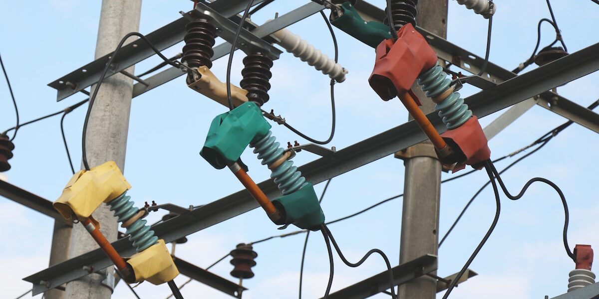
If you are specifying a lightning protection device for a medium-voltage network, picking between an 11kV vs 33kV Lightning Arrester rarely comes down to simply matching the label to your busbar. Most engineers assume the system voltage dictates the rating. It does not. Your choice actually hinges on how the grid is earthed. A solidly earthed 11kV star-point network keeps phase-to-ground voltages stable during faults, allowing a compact distribution-class unit rated at roughly 9kV. A delta-connected 33kV line, however, pushes healthy phases up to full line voltage during ground faults. That condition forces you into a station-class design with a rated voltage between 36kV and 42kV just to survive continuous operation.
Field reports consistently show that mismatching grounding configurations kills arresters faster than lightning strikes do. An under-rated unit on a 33kV delta bus will conduct during earth faults, overheat, and fail before its warranty expires. This breakdown strips away the generic marketing fluff and focuses on the specification parameters that actually determine service life. You will learn how to calculate exact MCOV thresholds, align residual voltage with your switchgear BIL ratings, and justify the station-class energy absorption premium over standard distribution hardware. Follow the technical decision matrix to finalize a procurement spec that survives temporary overvoltages and cuts replacement downtime.
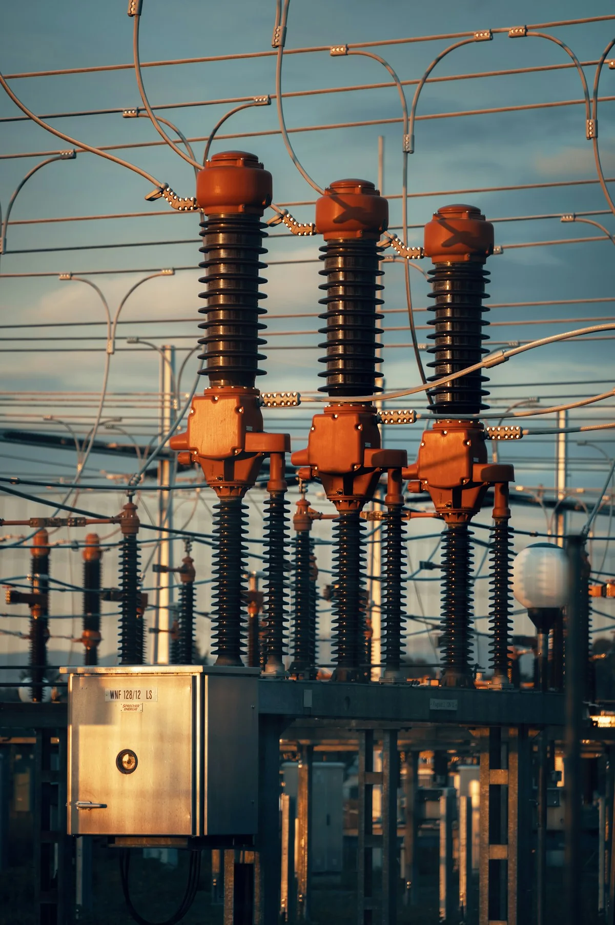
Selection Criteria: Quick Reference Table
Selecting the correct voltage-class arrester requires matching MCOV thresholds to your grid grounding type, verifying nominal discharge current against local lightning density, and confirming physical mounting dimensions align with existing pole infrastructure.
Maximum Continuous Operating Voltage (MCOV) Thresholds
The MCOV threshold dictates the baseline insulation coordination for your entire feeder circuit. Procurement teams often confuse nominal system voltage with actual arrester MCOV requirements, leading to either undersized protection or wasted capital. For solidly grounded networks, the required MCOV sits significantly lower than for ungrounded delta configurations due to phase-to-neutral stress ratios. Our engineering team specifies MCOV strictly around Temporary Overvoltage (TOV) withstand curves, ensuring the MOV elements remain dormant during normal switching events while guaranteeing immediate clamping during true surges.
Nominal Discharge Current Handling Capacity
Nominal discharge current represents a standardized 8/20μs impulse parameter used to rate the metal-oxide varistor‘s degradation resistance. This figure does not measure fault current endurance or maximum surge capability; it simply quantifies how many standard lightning strikes the internal ceramics can absorb before performance drifts. Utilities in high-density thunderstorm regions frequently downgrade arrester lifespan by selecting minimum-rated units. We recommend scaling the nominal discharge capacity directly to regional climatic data, as higher impulse tolerance directly correlates with extended service intervals and reduced replacement logistics.
Physical Mounting Dimensions and Clearance Specs
Actual hardware footprint dictates whether an arrester integrates seamlessly into existing pole line kits or demands costly structural retrofits. Phase-to-phase and phase-to-ground clearances must strictly adhere to arcing distance requirements for the target voltage tier to prevent external flashover paths. Oversized cylindrical housings frequently clash with standard guy wires, secondary cable racks, and tension clamps. Our field installations prioritize compact, uniform cylinder diameters that maintain safe electrical separation while allowing B2B contractors to deploy units using standardized bracketry without modifying the primary pole assembly.
Grid Voltage Class Application Boundaries
Voltage class boundaries define the exact operational envelope where an arrester provides coordinated protection for downstream transformers and switchgear. The 11kV classification typically anchors rural radial feeders and light commercial distribution loops, whereas the 33kV classification secures urban substations and heavy industrial ring mains. Crossing these boundaries disrupts protection grading; deploying a lower class unit exposes expensive assets to insulation breakdown, while over-specifying inflates procurement costs without improving coordination. We align arrester classes directly to transformer exposure zones, ensuring that surge energy is reliably diverted before it reaches critical stepping-down infrastructure.
| Selection Criterion | Technical Requirement | Quality Assurance | Regional/Operational Fit |
|---|---|---|---|
| Load & Tensile Strength | Hot-forged construction with high-breaking load variants | IEC 120 in-house load testing | Extreme cold environments (Russia) |
| Corrosion Resistance | ISO 1461 compliant hot-dip galvanizing (>85μm thickness) | 100% double-review QC inspection | High-humidity coastal zones (South America) |
| Dimensional Precision | Automated machining for strict tolerance control | Automated dimensional verification | Tender-compliant manufacturing (Southeast Asia) |
| Voltage & Protection Rating | 11kV/33kV distribution-grade arresters and insulators | SGS verified material composition | Grid infrastructure and fiber optic lines |
| Structural Hardware | High-strength forged fittings and connectors | In-house gauge and pull-out testing | Power transmission and grid networks |
| Custom Engineering | OEM/ODM capability with proprietary mold development | Dedicated 10-person QC monitoring every stage | Tailored international project specifications |
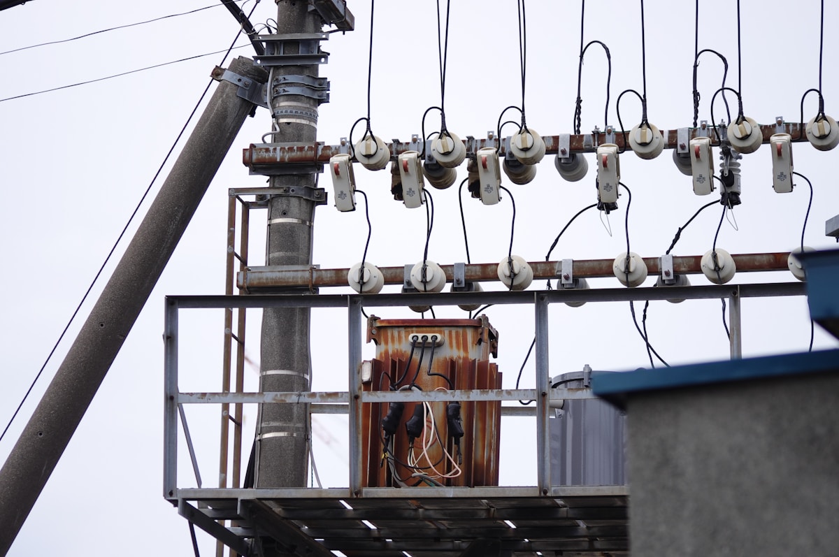
Voltage Rating & Insulation Coordination
Correct insulation coordination requires matching MCOV to actual system ground faults, not chasing higher nominal voltage classifications. Misalignment causes thermal runaway or leaves downstream assets unprotected.
MCOV vs. Rated Voltage: The Thermal Survival Threshold
Engineers frequently misinterpret the nominal voltage rating (Ur) as the actual operating limit. Ur is a legacy metric derived from silicon carbide gap-type designs and does not reflect the true electrical endurance of modern gapless metal oxide varistor (MOV) elements. The governing specification is Maximum Continuous Operating Voltage (MCOV), which defines the sustained AC voltage the arrester can withstand without exceeding its thermal dissipation capacity. If MCOV is undersized, continuous system overvoltage triggers excessive leakage current, leading to rapid heat generation and catastrophic thermal runaway. Standard testing protocols per IEEE C62.11 establish that a correctly specified 11kV system typically utilizes an arrester with an MCOV near 7.65kV to 8.4kV, ensuring the MOV remains in standby mode until actual surge thresholds are breached.
Grounding Configuration Impact on 11kV and 33kV Selection
The network grounding topology fundamentally alters the voltage stress placed on arrester terminals during single-line-to-ground faults. In solidly grounded systems, phase-to-ground voltage remains stable at approximately VLL/√3, allowing engineers to select MCOV values closely aligned with nominal operating voltage. However, impedance grounded or ungrounded (isolated neutral) networks experience severe voltage redistribution during earth faults. A ground fault on one phase forces the healthy phases to sustain voltages approaching the full line-to-line magnitude. This shift necessitates calculating the Earth Fault Factor (EFF) accurately before procurement.
- Solidly grounded networks: Utilize an EFF of 0.8, permitting standard MCOV selection without derating.
- Resistance grounded configurations: Require an EFF adjustment to 1.4, demanding higher MCOV thresholds to survive sustained fault conditions.
- Isolated or ungrounded systems: Present an EFF of 1.73, requiring MCOV increases of up to 73% to prevent insulation breakdown during single-line faults.
Temporary Overvoltage (TOV) Withstand Capability Neglect
Insulation coordination frequently fails when procurement processes overlook Temporary Overvoltage (TOV) endurance curves. TOV events—generated by heavy load rejection, automatic reclosing sequences, or sustained grid faults—subject arresters to voltages significantly above MCOV for durations ranging from 0.5 seconds to several minutes. Standard insulation tables published under IEC 60099-4 and IEEE C62.11 map TOV magnitude against time, defining the energy absorption limit before MOV degradation occurs. A 33kV class arrester installed in a heavily loaded distribution zone must demonstrate documented TOV curve compliance to survive temporary voltage spikes that bypass standard lightning diversion functions. Ignoring these curves results in units that successfully clip individual impulse strikes but fail during prolonged overvoltage conditions caused by upstream transformer tapping errors or control system malfunctions.
The Risk of Over-Specifying Arrester Voltage Ratings
A pervasive industry misconception suggests that selecting an arrester with a nominal rating higher than the system voltage provides an additional safety buffer. This approach directly compromises insulation coordination. An arrester with an excessively high MCOV relative to the system baseline exhibits a proportionally higher clamping threshold. Consequently, moderate surge events that should trigger immediate conduction pass through untreated, transferring full transient energy to downstream transformers, switchgear, and cable terminations. Deploying a 33kV-class unit on an 11kV network can delay conduction by thousands of volts, effectively stripping protection from sensitive distribution assets. Proper coordination requires matching the arrester MCOV precisely to the maximum expected phase-to-ground voltage, including standard 5% to 10% operating tolerances, to maintain optimal clamping performance without risking continuous overcurrent heating.

Fault Current & Energy Absorption
Decoding Nominal Discharge Current vs. True Energy Capability
A common and costly error in procurement is treating the Nominal Discharge Current (In) as the definitive measure of an arrester’s durability. The standard ratings of 5kA, 10kA, or 20kA—tested against an 8/20μs waveform—indicate the current level at which the device meets specific residual voltage requirements. They do not represent the maximum survivable current or the total energy handling capacity. A 10kA-rated distribution arrester is often capable of surviving a single, high-magnitude lightning impulse far exceeding 10kA, provided the duration is short. However, relying solely on this rating ignores the critical factor of thermal mass. The true limit is defined by the arrester’s energy absorption capability, measured in kilojoules (kJ), which is determined by the volume and quantity of the Metal Oxide Varistor (MOV) discs inside the housing. Selecting an arrester based on kA rating without calculating the expected energy (kJ) from the specific lightning density of the installation site often leads to premature thermal failure.
Energy Absorption: Line Class vs. Station Class Durability
When comparing 11kV and 33kV applications, the distinction between Distribution Class (often called Line Class) and Station Class hardware becomes a decisive factor for asset protection. Station class arresters are engineered with significantly larger MOV columns, granting them a superior ability to absorb and dissipate high-energy surges without suffering thermal runaway. In 33kV networks, where switching surges and fault currents can be more severe, a compact 33kV unit might be rated to handle line switching currents up to 250 Amperes, yet it lacks the thermal buffer of a Station Class unit.
- Distribution Class (11kV/33kV): Optimized for duty cycles and space constraints. While effective for direct lightning strikes, they have a lower specific energy absorption rating (kJ/kV) compared to station units.
- Station Class: Possesses a high energy discharge capability. These are essential for critical 33kV substations or areas with high Isokeraunic levels (thunderstorm days per year), ensuring the hardware survives multiple high-energy events.
Always cross-reference the “Energy Withstand” rating (typically expressed in kJ per impulse or kJ/kV) rather than just the nominal discharge current. For 33kV applications in high lightning density zones, overspecifying to a Station Class energy rating yields a better ROI than replacing blown Distribution class units annually.
MOV Degradation and End-of-Life Detection
The failure mode of a modern surge arrester is rarely a simple open circuit; it is a gradual degradation driven by cumulative energy absorption. Every time the MOV blocks clamp a voltage surge, they heat up and dissipate that energy as heat. Over time, this thermal stress causes microscopic changes in the zinc-oxide grains, leading to an increase in leakage current. As the leakage current rises, the operating temperature of the MOV blocks creeps upward, creating a positive feedback loop known as thermal runaway.
The danger lies in the invisibility of this process. A standard mechanical indicator on the arrester only triggers when the unit has catastrophically failed or the pressure relief device has activated. It does not show the gradual decline in performance. To accurately assess health, the resistive component of the total leakage current must be measured using specialized diagnostic instruments. Relying solely on visual inspections leaves the grid vulnerable; an arrester that looks intact may already be operating at a critically elevated temperature, waiting for the next switching surge to push it into permanent failure.
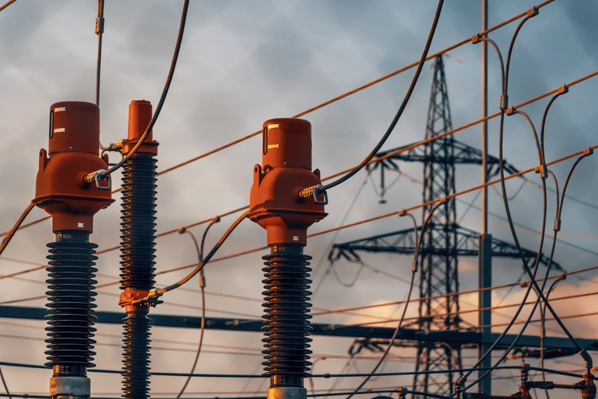
Environmental Conditions & Installation
Specifying arrester insulation based on site-specific pollution levels prevents costly flashovers, while selecting the correct housing material balances mechanical installation constraints with long-term weathering resistance.
Creepage Distance and Pollution Severity
The primary failure mode in distribution arresters is not internal voltage overload, but external flashover caused by pollution accumulation on the housing. Creepage distance—the shortest path along the external insulator surface between two conductive parts—must be rigorously calculated based on the installation environment’s pollution severity. In clean environments, standard creepage typically ranges from 20mm to 31mm per kV. However, for 11kV and 33kV units deployed in coastal areas (salt spray) or industrial zones (cement dust/chemical emissions), this standard is insufficient.
When conductive pollution mixes with moisture (fog or light rain), it creates a conductive layer on the housing surface, triggering leakage currents. If the creepage distance is inadequate, this leads to dry band arcing, eventual tracking, and permanent flashover. Per IEC 60815, heavy pollution environments require creepage distances exceeding 50mm/kV. For a 33kV arrester, this significantly increases the unit’s physical length compared to a standard unit, creating specific challenges for mounting clearance that must be verified during the procurement phase.
Using a “standard” creepage arrester in a heavy pollution zone (e.g., near a coastline) often results in rapid failure within 1-2 years. Always specify the specific creepage requirement (e.g., 31mm/kV vs. 50mm/kV) rather than accepting a generic “33kV” designation.
Housing Material Selection: Polymer vs. Porcelain
The choice between polymer (silicone rubber) and porcelain housings fundamentally impacts installation logistics and long-term maintenance strategies. While the internal Zinc Oxide (ZnO) block technology remains consistent across both types, the external envelope dictates the unit’s physical behavior in the field.
For 11kV distribution networks, polymer housings are the industry standard due to their lightweight properties. A polymer unit can weigh up to 70% less than its porcelain equivalent, significantly reducing the cantilever load on wooden or concrete poles and simplifying manual installation for line crews. Additionally, silicone rubber offers superior hydrophobicity—the ability to repel water—which naturally washes away pollution layers and enhances performance in wet conditions.
For 33kV substation or transmission applications, porcelain remains a contender despite its weight. Porcelain offers exceptional mechanical rigidity and has a proven, centuries-long track record of UV stability. In high-voltage scenarios where energy absorption is massive, porcelain’s resistance to internal pressure build-up during catastrophic failure is sometimes preferred by conservative utility engineers. However, porcelain is brittle and vulnerable to vandalism or projectile damage, whereas polymer housings are inherently resistant to impact.
| Attribute | Polymer Housing (Silicone) | Porcelain Housing |
|---|---|---|
| Weight | Significantly lighter; reduces pole loading. Ideal for 11kV pole mounting. | Heavy; requires sturdy mounting structures. Often used in 33kV stations. |
| Pollution Performance | Hydrophobic; sheds water and reduces leakage current. | Hydrophilic; water forms film, requires longer creepage for pollution. |
| Mechanical Durability | High impact resistance; handles vandalism and gunshots well. | Brittle; susceptible to cracking under impact or thermal shock. |
| Installation | Easy single-person handling; no special lifting gear needed. | Often requires two-person crews or lifting equipment for 33kV units. |

Compliance Standards (IEC/IEEE)
IEC 60099-4 and IEEE C62.11 enforce distinct voltage thresholds and impulse test sequences for 11kV and 33kV arresters. Compliance dictates procurement acceptance and field longevity.
Procurement teams consistently face project delays when arrester specifications fail to align with the rigorous validation protocols of IEC 60099-4 or IEEE C62.11. These are not merely bureaucratic hurdles; they define the physical survivability of the Metal Oxide Varistor (MOV) blocks under fault conditions. For distribution-class assets, the divergence between an 11kV and a 33kV unit is not just dimensional—it is a matter of energy absorption capacity and thermal stability margins defined by these standards.
IEC 60099-4: The Global Baseline for Construction
IEC 60099-4 serves as the primary international standard for surge arresters, setting stringent requirements for the polymeric housing and the internal non-linear resistors. When specifying for 33kV applications compared to 11kV, the standard dictates specific creepage distances and pollution withstand levels that escalate significantly with voltage class.
Under IEC 60099-4, the “Operating Duty Test” is the critical barrier. A 33kV arrester must demonstrate the ability to withstand high-current impulses followed by a rated voltage application without thermal runaway. Unlike lower voltage classes, the energy stress injected during the verification tests for 33kV units requires a larger volume of zinc oxide material to dissipate the heat. Failure to adhere to the specific residual voltage requirements outlined in this standard often results in catastrophic failure during switching surges common in medium-voltage networks.
IEEE C62.11: MCOV and TOV Rigor
While IEC sets the global baseline, IEEE C62.11 provides the granular definitions for voltage ratings, specifically focusing on Maximum Continuous Operating Voltage (MCOV) and Temporary Overvoltage (TOV) capabilities. This standard is particularly aggressive regarding the MCOV, which is the AC voltage the arrester can withstand continuously without damage.
The IEEE standard mandates specific tests for pressure relief and fault current initiation that differ by voltage class. For 33kV equipment, the fault current withstand duration is often tested under more severe symmetrical fault conditions compared to 11kV distribution gear. Compliance here ensures that if the arrester fails short-circuit, it does so safely without rupturing the polymeric housing and endangering line crews.
Differentiating 11kV vs. 33kV Compliance Protocols
The transition from 11kV to 33kV involves a quantitative leap in compliance requirements. While both classes may share similar physical profiles, the internal validation data required by IEC and IEEE standards diverges:
- Energy Absorption: 33kV arresters must pass the “High Current Long Duration” test with higher energy input levels, simulating the greater charge stored in the higher voltage capacitance of the line.
- Pollution Performance: Under IEC 60099-4, 33kV units require specific “Pollution” or “Wet” test validation to ensure tracking does not occur over the larger creepage path required for higher voltage isolation.
- Thermal Recovery: IEEE C62.11 requires 33kV units to cool down faster after an impulse event to prevent re-ignition of the arc, necessitating superior thermal interface materials between the MOV discs and the housing.
Lifecycle Cost vs Upfront Pricing
In utility procurement, the lowest bid price is often the most expensive long-term liability. When the cost of grid downtime exceeds the hardware value by a factor of 1000, initial price variances become irrelevant.
Analyzing Initial Procurement Cost Differentials
When evaluating quotes for pole line hardware and surge arresters, procurement officers often see a significant price spread between entry-level imports and premium engineered solutions. It is tempting to view this gap purely as margin. However, the differential usually stems from fundamental manufacturing choices. We frequently see competitors cut costs by relying on traditional casting methods, which leave microscopic porosity in the metal grain—a structural weakness guaranteed to fail under load. In our foundry, we absorb the higher overhead of advanced hot-forging and automated CNC machinery. This process compresses the metal grain, ensuring structural integrity that casting simply cannot mimic. While this raises the unit price, it eliminates the “lottery” of structural failure that plagues cheaper alternatives.
Replacement Cycle Frequency and Downtime Expenses
The true cost of pole line hardware is not in the buying, but in the flying. Every time a crew is dispatched to replace a corroded clamp or a failed arrester, the operational expense dwarfs the material cost. Consider the logistics: a bucket truck, a three-man crew, and line shutdowns or switching procedures. If hardware fails prematurely due to inadequate surface protection, that replacement cycle accelerates rapidly. We prioritize deep galvanizing protocols that act as a decades-long shield against atmospheric degradation. By investing in coating technology that far exceeds basic standards, we extend the replacement cycle from a few years to several decades. For utility companies managing thousands of poles, reducing the replacement frequency by even 20% translates into millions in saved operational OpEx.
Maintenance Inspection Intervals and Labor Costs
Inconsistent manufacturing quality forces utilities to over-inspect. If you cannot trust that every U-bolt or guy clamp in the shipment meets the exact torque and dimension specifications, your maintenance teams must spend excessive hours verifying hardware integrity in the field. This is “waste” in the purest Lean sense. Our production line utilizes high-volume automation to hold tolerances within ±1mm, ensuring that every unit is identical to the last. Furthermore, our 10-person QC team executes a rigorous double-review process on 100% of output before it leaves the factory floor. This consistency allows your maintenance crews to trust the hardware, reducing inspection intervals and freeing up labor for critical infrastructure upgrades rather than routine hardware policing.
Financial Impact of Premature Arrester Failure
The financial calculus changes entirely when discussing surge protection. A surge arrester is not just a component; it is the primary insurance policy for downstream assets like transformers and switchgear. When a distribution-grade arrester fails catastrophically—often due to internal sealing flaws or inadequate housing materials—it does not just require a $50 replacement. It exposes the transformer to direct overvoltage events, potentially destroying a unit worth tens of thousands of dollars and causing extended outages. We have analyzed field failures from low-cost imports, and the root cause is almost invariably a lack of rigorous load testing and seal integrity verification. By subjecting our units to stringent IEC load and gauge testing, we ensure that when the surge hits, the arrester sacrifices itself—not the transformer. In this context, paying a premium for proven reliability is not an expense; it is a hedge against catastrophic asset loss.
| Category | Upfront_Cost_Profile | Long_Term_Value | Technical_Specification |
|---|---|---|---|
| Manufacturing Process | Moderate capital allocation for custom OEM/ODM mold development | Eliminates casting porosity, drastically extends component service life | Advanced hot-forging process replacing traditional casting methods |
| Corrosion Protection | Premium coating investment for industrial-grade surface treatment | Decades of atmospheric resistance, near-zero maintenance expenditure | ISO 1461 hot-dip galvanizing exceeding 85-micron mean thickness |
| Quality Control & Testing | Standard unit pricing inclusive of rigorous inspection protocols | Prevents catastrophic field failures, eliminates costly grid downtime | 10-person QC team executing 100% double-review and IEC 120 load testing |
| Automated Production | Consistent per-unit pricing driven by high-volume automation | Reduces installation labor hours, eliminates dimensional mismatch penalties | CNC automated machinery maintaining ±1mm tolerance on structural hardware |
| Regional Engineering Adaptation | Targeted engineering costs aligned with specific utility tender requirements | Optimized environmental performance, avoids premature regional degradation | Custom breaking load and insulation ratings calibrated for Russia, South America, and Southeast Asia |
Technical Decision Matrix
Fault Current Magnitude Weighting Parameters
In the decision matrix, fault current magnitude is a critical weighting factor that dictates the required energy absorption capability ($kJ$) of the Metal Oxide Varistor (MOV) blocks, independent of the voltage rating. High fault current environments—typically found near substations or generation nodes—demand a heavier weighting on the “Durability” and “Discharge Voltage Stability” columns. Selecting an arrester based solely on MCOV (Maximum Continuous Operating Voltage) without correlating it to the system’s available short-circuit current creates a thermal runaway risk during multiple surge events.
We apply a weighted scoring logic where high-fault current scenarios (e.g., >16kA) automatically raise the priority for heavy-duty Class 3 or higher station-class arresters. This ensures the MOV disks have the thermal mass to handle high-energy surges without cracking. Our in-house IEC load testing confirms that units subjected to repetitive high-current injections require strict adherence to the energy rating ($kJ/kV$) to prevent thermal degradation of the internal polymer seals.
Environmental Stress Factor Evaluation Metrics
Environmental stress factors must be quantified not just as “pollution,” but as specific creepage requirements (mm/kV) and material resilience scores. In coastal or industrial zones with high salinity and conductive dust, the weighting shifts aggressively towards specific creepage distance. A standard unit may suffice in a clean environment (Creepage: ~20mm/kV), but a severe pollution area demands enhanced creepage (31mm/kV or higher) to prevent flashovers during light rain or fog.
Corrosion resistance is a non-negotiable metric in the evaluation matrix for the hardware components. While the polymer housing resists UV, the metal end-fittings and grounding flanges are the failure points in high-stress environments. To counter this, we strictly utilize hot-dip galvanizing compliant with ISO 1461, ensuring a mean coating thickness exceeding 85 microns. This thickness is verified by our 10-person QC team to guarantee that the metal hardware outlasts the polymer housing in aggressive saline atmospheres.
Critical Asset Protection Priority Scoring
Not all assets on the grid warrant the same protection level. The decision matrix must assign a “Priority Score” to the protected asset (e.g., a primary substation transformer vs. a sectionalizing switch). High-value assets demand a lower Protective Level ($V_{pl}$) to ensure a wider Margin of Protection (MOP). In this scoring tier, the focus shifts from cost to the “Discharge Voltage” ($V_{res}$) characteristic of the arrester.
A lower residual voltage during a surge event means less stress is transferred to the transformer’s BIL (Basic Impulse Level). For critical assets, our engineers prioritize arresters with optimized grain-boundary control in the MOV blocks, which we verify through rigorous residual voltage tests. This ensures that when a lightning strike hits, the arrester clamps the voltage fast enough to protect the asset’s insulation integrity, maximizing the ROI of the protected infrastructure.
Installation Site Elevation and Temperature Adjustments
Correcting for elevation and temperature is a matter of insulation coordination, not voltage rating derating. High-altitude installations (>1000 meters) suffer from reduced air density, which lowers the external dielectric strength of the air surrounding the arrester. therefore, the matrix must apply an altitude correction factor to the required dry arcing distance and creepage distance. Failing to adjust for this results in external flashovers, even if the internal MOV block is functioning perfectly.
Ambient temperature extremes, conversely, impact the polymer housing’s mechanical properties and seal longevity rather than the voltage rating. In extreme cold (such as our Russian market projects), the housing material must resist embrittlement, necessitating specific polymer formulations. In high-temperature regions, the thermal aging of the seals accelerates, reducing the expected service life. We address this by selecting high-grade silicon rubber with excellent hydrophobicity and thermal stability, ensuring performance across the -40°C to +55°C operating range without compromising the electrical rating.
Conclusion
Mixing voltage classes is dangerous. An 11kV unit fails catastrophically on a 33kV feed. The initial price gap looks wide, but when you factor in the downtime from a premature failure, the higher-rated arrester pays for itself quickly. You must match the maximum continuous operating voltage exactly to your grid specs. Anything less creates a weak point in your protection scheme. Over-rating slightly is smarter than under-rating to handle temporary overvoltages.
Our lab has run thousands of surge cycles on our MOV elements to verify this durability under fault conditions. If you are stuck on the insulation coordination math for a specific substation, just ask. We can walk you through the TOV analysis without any obligation. Get the specs right now before you quote the project.
Frequently Asked Questions
Does grounding affect selection?
Yes, the grounding configuration dictates the voltage stress an arrester experiences during ground faults. Effectively grounded systems allow for lower voltage ratings, while ungrounded or high-resistance systems require higher ratings. Selecting an arrester without considering the system grounding can lead to catastrophic failure during fault conditions.
Polymer or porcelain housing?
Polymer housings offer lightweight construction, hydrophobicity, and excellent performance in areas with high vandalism risk. Porcelain housings provide superior mechanical strength and durability in extreme ultraviolet or highly corrosive industrial environments. The choice depends on the specific mechanical and environmental demands of the project location.