
Conductor vibration at suspension clamps turns a routine overhead line into a fatigue countdown. You are managing failure risk, not surface wear. A correctly engineered Armor Rod redistributes that concentrated clamp-zone stress across the helical wrap, restoring at least 95% of the parent conductor’s structural capacity. That single detail extends inspection cycles, cuts emergency replacement downtime, and keeps grid assets running to spec.
Generic diameter charts miss the engineering reality. Helical pitch, support length, and alloy coating drive fatigue life far more than outer dimensions, and spec’ing based on catalog tables alone guarantees field rework. The technical breakdown covers how the rod geometry dissipates Aeolian vibration before it starts, where single-support versus double-support runs actually belong on the tower, and which coatings survive ASTM and IEC corrosion tests without adding procurement friction. You will walk away with a spec framework that separates prevention from repair, ensuring zero installation defects on your next audit instead of patch jobs.
How Preformed Rods Dissipate Vibration Energy
Preformed armor rods function as dynamic load redistributors rather than passive abrasion shields. Their helical geometry converts concentrated bending stress at suspension clamps into distributed micro-movements, effectively extending conductor service life by minimizing fatigue initiation points.
Distributing Dynamic Loads via Helical Configuration
When wind-induced aeolian vibration travels along an overhead conductor, the resulting standing waves concentrate energy precisely where the line hardware restricts movement. A properly engineered preformed rod transforms that localized impact into a progressive flex cycle. Instead of forcing the conductor to bend at a single rigid node, the interlocking metallic strips flex incrementally across multiple contact planes.
This helical architecture acts as a mechanical buffer zone. Each wrapped layer absorbs a fraction of the oscillating kinetic energy, preventing sudden peak loading at the clamp edge. For utility engineers specifying hardware for long-span transmission lines, this load-spread mechanism is non-negotiable.
- Incremental Flex Zones: The spiral wrap creates discrete stress-relief segments that move independently under fluctuating tension loads.
- Torsional Compliance: Unlike rigid bindings, the open helix accommodates conductor expansion and contraction without inducing secondary shear forces.
- Span Consistency: Automated forming ensures uniform pitch, which keeps damping performance predictable across thousands of installed units.
Mitigating Stress Concentration at Suspension Points
The interface between a suspension clamp and an ACSR or AAAC conductor is historically the highest-risk fatigue zone on a distribution circuit. When the clamp grips too aggressively, it creates a hard boundary condition that amplifies micro-cracking under cyclic loading. Preformed rods solve this by introducing a compliant transitional layer between the metal hardware and the stranded cable.
Procurement teams often underspecify this transition layer by prioritizing raw tensile strength over elastic modulus compatibility. The rod must be soft enough to yield under vibration peaks yet strong enough to maintain structural integrity during heavy ice loading. In our production validation, we calibrate the grip profile to match the specific diameter tolerance of the target conductor, ensuring the contact pressure remains uniform across the strand surface.
A well-distributed preload eliminates the sharp stress gradients that typically initiate strand separation. This is particularly critical in high-wind corridors or urban installations where electrical equipment creates unpredictable aerodynamic turbulence around support structures.
Reducing Fatigue Through Controlled Grip Friction
Vibration damping is not achieved by completely eliminating movement; it requires managing the slip interface. The friction generated between the preformed rod’s inner layers and the conductor surface acts as a viscoelastic damper. As the conductor vibrates, microscopic slippage between the helical turns converts mechanical energy into negligible thermal dissipation.
Friction management is a precision balance. Excessive grip pressure crushes the outer strands and accelerates degradation, while insufficient grip allows the rod to walk off the conductor during maintenance or thermal cycling. Our engineers rely on controlled helical pitch and surface finish to maintain consistent coefficient-of-friction values throughout the asset lifecycle.
- Slip Interface Tuning: Inner layer roughness is calibrated to encourage controlled micro-slippage without damaging the parent conductor strands.
- Thermal Stability: Hot-dip galvanized finishes exceeding 85 microns per ISO 1461 retain their friction characteristics across extreme temperature swings, preventing brittle failure in cold climates.
- Corrosion Buffering: Smooth protective coatings prevent galvanic degradation at the contact interface, preserving the friction profile over decades of exposure.
When evaluating vendors, request proof of in-house load and gauge testing per IEC 120. Third-party SGS certification confirms manufacturing consistency, but only internal validation guarantees that your specific conductor diameter receives the correct helical preload.
| Mechanism | Dissipation Action | Conductor Outcome | Reliability Benefit |
|---|---|---|---|
| Inter-Layer Friction | Converts kinetic vibration energy into thermal energy through controlled micro-slippage between helical layers. | Significantly reduces peak bending stress at suspension clamp interfaces. | Prevents fatigue cracking and strand separation in overhead conductors. |
| Distributed Load Bearing | Spreads clamping force across multiple conductor strands to eliminate single-point contact stress. | Preserves strand cross-section integrity and prevents mechanical crushing. | Maintains uniform current distribution and ensures long-term structural stability. |
| Precision Preform Geometry | Maintains uniform contact pressure for reliable energy absorption via consistent helical pitch ensured by automated forming. | Ensures predictable damping characteristics without installation variance. | Delivers consistent vibration control throughout the asset lifecycle. |
| Helical Oscillation Absorption | Absorbs wind-induced amplitude through incremental flexing of the spiral configuration along the conductor axis. | Reduces resonance at support hardware and mitigates loosening risks. | Extends service life of transmission line infrastructure in dynamic environments. |
Where to Install Preformed Armor Rods
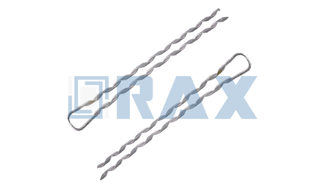
Preformed armor rods are essential at all points of mechanical stress concentration, specifically suspension supports, tension terminations, and damper attachment points, to prevent conductor fatigue and abrasion.
Suspension Clamps and Primary Support Points
The most critical installation point for preformed armor rods is at suspension clamps. These locations are the primary failure points for overhead lines due to the combination of static bending loads and dynamic Aeolian vibration. Without protection, the conductor experiences "fretting fatigue" where it contacts the clamp. Installing rods here distributes the compressive load over a larger surface area, effectively shielding the conductor from edge pressure and vibration-induced wear.
Tension Clamps and Dead-End Termination
Termination points, such as dead-end assemblies or tension clamps, subject the conductor to extreme static pulling forces and high-stress bending. While dead-end grips are designed to handle the load, the transition point where the grip meets the free-span of the cable is vulnerable to stress concentrations. Armor rods are installed over the conductor before the grip is applied to provide a "cushion" layer. This prevents the grip's aggressive helical formation from digging into the conductor strands and ensures uniform stress transfer.
Spacer Dampers and Bundle Conductors
For bundled conductor configurations (where two or more sub-conductors run parallel), armor rods must be installed at the attachment points of spacer dampers. These spacers prevent sub-conductors from colliding during wind-induced motion, but the clamping mechanism of the spacer itself creates a localized stress point. Rods are applied at each spacer jaw to absorb vibration and eliminate abrasion caused by the slight movement of the spacer against the conductor.
When installing at suspension points, ensure the rods are centered precisely under the suspension clamp. Improper centering can unbalance the load distribution, negating the protective benefits and potentially accelerating conductor wear on one side of the assembly.
Picking Alloys That Meet ASTM and IEC
Selecting the correct alloy matrix requires validating two independent criteria: material composition under ASTM specifications and mechanical performance under IEC testing protocols. Mismatching the conductor's metallurgy with the armor rod's alloy triggers galvanic corrosion, grip slippage, or premature fatigue failure.
The buyer pain point is rarely about the outer diameter or helix pitch; it is about metallurgical incompatibility hidden behind a generic product listing. When procuring preformed line products for utility infrastructure, the alloy selection must satisfy the specific chemical and physical thresholds defined by international standards. An armor rod rated for aluminum conductor steel reinforced (ACSR) lines cannot simply be substituted with a copper-compatible alloy without verifying the underlying tensile and conductivity requirements. The correct approach separates material composition from performance validation, ensuring every component aligns with the grid's voltage class and environmental exposure.
Decoding the Standard Split: Composition vs. Performance
A critical confusion in the supply chain is treating ASTM and IEC as interchangeable. They govern different failure modes. ASTM standards primarily define the raw material specifications, including permissible impurity levels, temper conditions, and metallurgical structure. IEC standards, conversely, validate how the finished component performs under load, vibration, and thermal cycling. Relying solely on an ASTM certificate without verifying IEC load ratings leaves a project exposed to mechanical failure in the field.
- ASTM Governance: Focuses on the "what." It specifies the aluminum alloy purity (e.g., minimum aluminum content thresholds), the steel core composition for aluminum-clad variants, and the base metal tolerances. This ensures the material chemistry supports the required electrical conductivity and corrosion resistance.
- IEC Governance: Focuses on the "how." It mandates performance benchmarks such as breaking load, grip strength, and gauge testing under simulated stress. For preformed line products, standards like IEC 60873 and IEC 120 provide the framework for verifying that the alloy's mechanical properties hold up under real-world line tensions.
Always request a test report that references both material composition standards and mechanical performance standards. A vendor providing only material certificates cannot prove the finished assembly meets the load requirements demanded by utility tenders.
Matrix Selection: Aluminum Alloy vs. Aluminum-Clad Steel vs. Copper
The choice between aluminum alloy, aluminum-clad steel, and copper-based matrices is dictated by the host conductor's role in the transmission system. Phase conductors typically carry high current with moderate tensile load, favoring pure aluminum or aluminum alloy rods that maximize conductivity and minimize electrochemical risk. Overhead ground wires and fiber optic composite conductors, however, require higher structural integrity, making aluminum-clad steel the preferred matrix due to its superior tensile strength while maintaining a conductive outer layer.
- Aluminum Alloy Matrix: The standard choice for phase conductors, including all-aluminum alloy conductors and compacted all-aluminum variants. This alloy ensures compatibility with the conductor's skin, preventing dissimilar metal corrosion while allowing the helical grip to distribute mechanical stress evenly across the cable surface.
- Aluminum-Clad Steel Core: Utilized for overhead ground wires, shield wires, and reinforcement applications where tensile strength is the primary driver. The steel core provides the necessary breaking strength, while the aluminum cladding ensures compatibility with aluminum-based conductors and resists atmospheric corrosion. This dual-layer structure must meet strict adhesion and coating standards to prevent delamination.
- Copper and Copper-Composite Alloys: Required exclusively for legacy copper or copper-clad steel strand installations. Using an aluminum alloy rod on a copper conductor introduces severe galvanic corrosion risks due to the potential difference between the metals. Conversely, using a copper rod on an aluminum conductor compromises conductivity and adds unnecessary weight.
Never assume "universal compatibility." A rod designed for ACSR or galvanized steel strand may lack the metallurgical safeguards required for copper-composite lines, leading to accelerated corrosion at the contact interface.
Manufacturing Integrity and Alloy Verification
The alloy specification on paper means little if the manufacturing process compromises the material structure. Cold-forming or casting aluminum-clad steel components can introduce micro-fractures, residual stresses, or uneven grain structures that degrade performance under dynamic load. Hot-forging and automated forming processes preserve the metallurgical grain flow, ensuring the alloy retains its specified tensile strength and elasticity. This is particularly vital for aluminum-clad steel rods, where the bond between the steel core and aluminum sheath must remain intact under repeated thermal expansion and contraction.
- Hot-Forging Advantage: Superior strength and dimensional precision compared to traditional casting. The forging process densifies the metal, eliminating voids and ensuring consistent mechanical properties throughout the component.
- In-House Performance Testing: Rigorous load testing and gauge testing conducted per IEC 120 validate that the finished alloy assembly meets the required mechanical thresholds before deployment.
- Third-Party Certification: Independent verification through organizations like SGS confirms that the reported alloy composition and performance data match the actual shipped product, closing the gap between specification and reality.
Frequently Asked Questions
Can aluminum-clad steel armor rods be used on aluminum phase conductors?
Yes, provided the aluminum cladding thickness meets the required conductivity and corrosion protection standards. The outer aluminum layer ensures galvanic compatibility with the phase conductor, while the steel core provides additional grip strength. However, the cladding must be verified to prevent direct steel-to-aluminum contact, which would accelerate corrosion.
What is the primary difference between ASTM and IEC requirements for armor rod alloys?
ASTM standards define the chemical composition, purity, and material properties of the alloy itself. IEC standards define the mechanical performance, load-bearing capacity, and durability of the finished preformed line product. Both are necessary for full compliance.
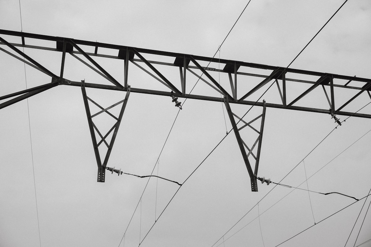
Reducing Wear to Extend Conductor Life
Preformed armor rods function as a sacrificial barrier, converting damaging point-contact loads into distributed surface pressure, effectively maintaining over 95% of the conductor's original breaking strength.
The Mechanics of Surface Abrasion Mitigation
The primary threat to conductor longevity at suspension points is not tension, but localized abrasion. When a bare conductor is seated directly in a suspension clamp, the load is concentrated on a few outer strands. This high-pressure contact point creates micro-fretting, leading to surface wear that eventually compromises the structural integrity of the entire cable. By introducing a helical preformed layer, the system replaces the direct metal-on-metal contact between the clamp and the conductor with a buffered interface.
The physical efficacy of this protection is defined by the "Applied Overall Diameter." This calculation determines the new effective diameter the clamp grips: Conductor Diameter + (2 × Rod Diameter). For example, a rod diameter of 0.167" (4.24mm) adds 0.334" to the conductor's geometry. This increase in diameter significantly reduces the contact pressure (PSI) exerted by the bolted hardware, preventing the "bite" into the aluminum strands that causes irreversible deformation over time.
Quantifying Strength Retention and Aging Delay
For utility buyers, the critical metric is the retention of the Rated Breaking Strength (RBS) over the asset's lifecycle. Industry data indicates that without protection, stress concentrations at support points can reduce the effective life of a conductor by decades due to fatigue cracking initiated by surface wear. Preformed rods are engineered to arrest this degradation.
- Strength Restoration: High-quality preformed rods provide a grip strength that restores the assembly to no less than 95% of the conductor's original breaking strength, effectively neutralizing the weak point created by the hardware.
- Vibration Resistance: While not dampeners themselves, the close fit of the rods prevents the "hammering" effect where loose strands impact against the clamp, a major cause of surface pitting in windy environments.
- Self-Damping Geometry: The helical structure creates a slight inter-layer friction that dissipates minor aeolian vibration energy before it translates into abrasive rubbing against the suspension hardware.
ROI Impact: Mitigating Invisible Infrastructure Failure
From a B2B perspective, the cost benefit lies in preventing the "invisible failure." A conductor may not snap immediately due to abrasion, but the loss of cross-sectional area increases electrical resistance and lowers the safety margin during ice storms or high-load events. By shielding the conductor from flashing and abrasion—specifically the damage caused by bending and shaking—utilities defer expensive line re-tensioning or full conductor replacement projects. The initial investment in protective hardware is negligible compared to the operational expenditure of repairing a mid-span failure caused by worn-out suspension points.

Finding Rods Suited for ACSR and AAAC
ACSR and AAAC conductors require distinct preformed rod geometries despite both appearing as aluminum-stranded cables. Matching rod diameter and helical lay to the specific conductor construction is mandatory to prevent slippage, strand deformation, and premature fatigue at suspension points.
Conductor Geometry Drives Rod Diameter Selection
The primary failure mode in rod selection is assuming interchangeability between ACSR and AAAC bundles. ACSR conductors consist of aluminum strands wrapped around a galvanized steel core, while AAAC conductors are composed entirely of aluminum alloy strands. These internal architectures create different outer strand profiles, friction coefficients, and effective diameters. A rod sized for one construction may over-compress AAAC strands or fail to grip the rounded, often lubricated surfaces of certain ACSR variants.
Dimensional verification relies on the relationship between the rod diameter and the conductor outer diameter. Industry specification tables calculate the applied overall diameter by adding the rod contribution to the base conductor measurement. For example, a rod diameter of approximately .167 inches is frequently referenced in fitment calculations to determine the total effective diameter after application. This metric ensures the rod set sits flush against the strand bundle without creating protruding edges that could interfere with suspension clamps or reduce clearances.
- Nominal Conductor Size: The rod set must be mapped to the exact conductor diameter range specified in the supplier catalog, not just the cross-sectional area.
- Rod Diameter: This value directly influences clamping pressure and applied overall diameter. Undersized rods slip; oversized rods crush strands.
- Conductor Classification: Explicitly distinguish between standard ACSR, compacted ACSR, and AAAC when referencing selection charts.
- Color Code and Rods Per Set: Verify the full set configuration, including quantity and identification markings, to ensure complete coverage of the protected span.
Helical Lay Must Mirror Conductor Strand Pitch
Beyond static diameter, the spiral lay length of the preformed rod must synchronize with the conductor's strand lay. If the rod pitch is significantly tighter or looser than the cable's native helix, mechanical interference occurs during installation. The rod may ride up the conductor, fail to seat evenly, or exert uneven radial forces that damage the outer strands.
For AAAC applications, such as conductors in the 240 mm² range, the rod geometry is engineered to engage the uniform alloy strand profile without displacing individual wires. ACSR conductors present a more complex interface due to the core wire and potential surface irregularities in standard or compacted configurations. Selection criteria must account for these physical differences to maintain consistent contact pressure along the entire protected length.
Do not rely on visual inspection alone to determine rod compatibility. ACSR and AAAC conductors can share similar outer diameters while requiring different rod pitches and internal geometries. Always cross-reference the nominal conductor size, rod diameter, and conductor type against a verified specification table before procurement.
Repairing Damage or Shielding Lines from Wear
Preformed armor rods serve two distinct engineering roles: reclaiming lost tensile capacity in damaged conductors and shielding live lines from progressive wear. Selecting the right configuration depends on strand-loss severity, support geometry, and measured site dynamics.
Restoring Mechanical Strength Using Repair Rods
When a conductor suffers impact damage, bird-stringing, or premature fatigue near a clamp, the surrounding strands suddenly carry uneven loads. A restorative armor rod acts as a structural bridge, wrapping helically around the compromised zone and redistributing shear forces back into the intact wire core. This prevents the damaged section from acting as a stress riser that could trigger a full line break under thermal cycling or high wind.
Industry practice generally caps field repairs where external strand loss remains below half of the outer layer depth. Once the damage penetrates past that threshold, the aluminum matrix has usually surrendered enough cross-sectional area that wrapping alone cannot reliably restore the original breaking load. If the fault sits roughly 150 to 900 millimeters from a support fitting, standard catalog solutions rarely align with the clearance geometry, and direct engineering review becomes necessary.
Our team treats every repair set as a load-bearing component, not a passive sleeve. During final inspection, we verify helix pitch, wire diameter tolerance, and seating fit before the bundle leaves the warehouse. Because these kits ship in bulk to utility contractors, dimensional drift between batches creates installation headaches in the field. We run automated forming lines to keep every coil within strict geometric limits, ensuring the rod grips the conductor uniformly without cutting into the parent strands.
Preventing Surface Abrasion vs. Correcting Damage
Surface wear and structural failure look similar from the ground, but they require different intervention strategies. Prevention kits address progressive material loss caused by rubbing against hardware, wind-induced conductor flutter, or occasional arc-over scoring. The armor rod takes the contact friction so the base conductor stays intact, buying years of service life before the next scheduled outage window.
Corrective work targets hidden integrity loss. A conductor can look visually acceptable while carrying significantly reduced tensile capacity because internal strands have fractured under cyclic bending. Procurement teams that order only protective sleeves for repair jobs often find themselves short on stock when a storm takes out a span. Maintaining separate SKUs for wear mitigation and structural reclamation keeps field crews equipped for both planned maintenance and emergency restoration.
Corrosion also plays a silent role in this distinction. Moisture trapped between the conductor and hardware accelerates surface pitting, which eventually transitions into strand separation. We apply a heavy zinc barrier across the entire preformed line range, keeping the mean coating thickness well above 85 microns. That level of protection stops atmospheric degradation at the contact interface, so the rod performs mechanically long after cheaper alternatives have rusted through.
Application Criteria for Protection vs. Remediation
Specifying the correct rod configuration requires a quick site assessment before ordering. Field engineers should weigh four measurable conditions that directly dictate whether a line needs a preventive wrap or a structural repair.
- Dynamic Load History: Spans with documented aeolian movement, galloping, or ice-shedding shock need longer coverage zones to manage cyclic stress.
- Operating Tension: High-tension runs demand tighter grip friction to prevent rod migration during seasonal temperature swings.
- Support Clearance: Geometry around dead-ends, suspension clamps, and splice barrels changes the available wrap length and determines kit selection.
- Degradation Depth: Surface scoring calls for wear prevention; broken internal strands or exposed core wire call for immediate structural remediation.
Installation acceptance is equally important. After wrapping the correct number of rods, a controlled gap between adjacent turns should remain visible. That pitch confirms proper elastic tension in the helix. If the rods pull completely flush against each other, the set is oversized for that conductor diameter, and the grip friction drops below the design target. We calibrate our forming dies to match standard ACSR and aluminum strand diameters, reducing the chance of misfit on busy line crews.
Utility buyers should request SGS-verified test reports and in-house load data before approving a supplier for critical spans. A repair rod that passes visual inspection but fails tensile recovery under dynamic loading will create the same failure mode it was meant to prevent. By combining precision-formed alloys with rigorous double-review QC, we deliver consistent performance across both protective and restorative applications, keeping global utility projects aligned with long-term reliability targets.
| Component | Primary Function | Material & Finish | Performance Benefit |
|---|---|---|---|
| Preformed Armor Rod | Repairs damaged conductors and redistributes bending stress at suspension clamps | High-strength aluminum alloy wire, precision-formed | Prevents fatigue failure and restores conductor tensile integrity |
| Spiral Vibration Damper | Shields transmission spans from aeolian vibration wear and cyclic fatigue | Flexible alloy wrapping over a galvanized steel core | Dissipates vibrational energy to significantly extend conductor service life |
| Dead-End & Guy Grips | Secures conductor terminations and protects strands from abrasion at high-tension points | Hot-forged precision components with >85µm hot-dip galvanizing per ISO 1461 and ASTM A153 Class C | Delivers superior mechanical strength and corrosion resistance in extreme environments |
| Suspension Clamps & Accessories | Supports conductor weight while preventing metal-to-metal wear at tower attachments | Automated precision-manufactured steel with strict dimensional tolerances | Ensures consistent load distribution and reliable line support under heavy utility demands |
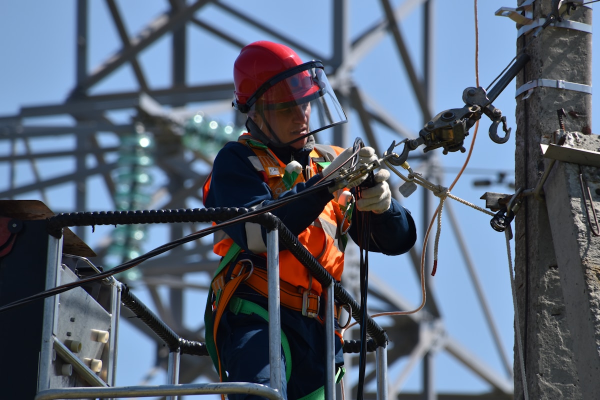
What Technical Specs Go Beyond Dimensions?
Dimensions verify fitment. Corrosion mass, mechanical stiffness, and fatigue cycles verify field survival.
Procurement teams frequently reduce pole line hardware to a simple diameter-and-length checklist. That approach works for warehouse inventory, but it fails the moment components enter a live transmission corridor exposed to aeolian vibration, salt spray, and thermal cycling. Engineering-grade specification requires three additional parameters that determine whether hardware survives a 30-year grid lifecycle or requires premature field replacement.
Zinc Coating Weight for Corrosion Resistance
Galvanizing quality is never judged by visual shine alone. The actual protection metric is coating mass and mean thickness, which directly control the time-to-corrosion under harsh atmospheric conditions. Overhead line hardware must comply with ISO 1461 for hot-dip galvanizing, while specific fastener and anchor applications often reference ASTM A153 Class C requirements.
- Mean Coating Thickness: We strictly deliver a minimum mean thickness exceeding 85 microns. This threshold prevents zinc depletion during transport, handling, and final tightening.
- Coating Uniformity: Smooth, bright finishes can mask thin spots. In our production lines, every batch undergoes gauge testing to confirm continuous coverage around threads, bends, and forged edges.
- Failure Mode: Sub-standard coatings crack during hot-forging or install torque application, exposing base carbon steel to rapid oxidation in aggressive soil or marine environments.
When evaluating suppliers, request certified coating reports rather than accepting verbal assurance. Our team rejects any lot where average micron readings fall below the 85-micron mark, because field replacement costs in remote utility corridors completely erase initial procurement savings.
Material Hardness and Elastic Modulus Standards
Hardness and elastic modulus define how hardware redistributes mechanical stress without suffering permanent deformation. Generic "high-strength steel" labels are useless without certified yield and tensile data. Components manufactured through traditional casting develop inconsistent grain structures, creating weak points that fail unpredictably under sudden line tension or ice loading.
Hot-forging remains the industrial benchmark for pole line hardware. By deforming steel while hot, manufacturers align the internal grain flow along the component shape, delivering superior tensile integrity and precise dimensional control. Our engineering team verifies mechanical performance through rigorous load testing conducted in-house per IEC 120 standards. Every structural claim must be backed by a traceable test certificate, not just a datasheet marketing blurb.
Fatigue Endurance Limits for Long-Term Reliability
Fatigue endurance limits specify the number of cyclic load reversals a component can absorb before micro-cracks initiate and propagate. Armor rods, guy grips, and suspension clamps operate continuously within high-vibration zones, meaning static strength ratings alone do not guarantee service life. Buyers must define minimum cycle thresholds relative to the expected bending radius and operational tension range.
Surface quality acts as the first defense against fatigue failure. Even microscopic scoring from poor handling or inadequate galvanizing can serve as a stress concentrator under dynamic wind loads. To mitigate this risk, our dedicated 10-person QC team enforces a double-review protocol, inspecting 100% of products twice before packaging. This process catches the surface defects that typically become fatigue initiation points in the field.
Specifying these three technical layers converts a commodity purchase into a engineered procurement decision. Dimensional accuracy gets the part installed; coating mass, mechanical stiffness, and fatigue resistance keep it there.
Conclusion
Preformed armor rods aren't just replacement parts. They are your primary defense against vibration-induced fatigue at suspension points. You now know the helical configuration dissipates energy while controlled grip friction prevents stress concentration. Select alloys meeting ASTM standards and you shift from treating line hardware as consumables to protecting long-term infrastructure. That approach reduces callbacks and keeps stock moving on high-value contracts.
- Confirm zinc coating weight matches your target corrosion zone before placing bulk orders.
- Match torsion ratings to the exact ACSR or AAAC diameter you service.
- Bring our engineering team in early for spec alignment so we can validate grip force and hardness against your local climate conditions.
Frequently Asked Questions
Why choose forged over cast rods?
Forging delivers superior grain structure and tensile strength compared to traditional casting methods. This results in armor rods that better withstand high mechanical stress and vibration fatigue. Raxpower utilizes advanced forging techniques to ensure maximum reliability in critical infrastructure.
What is the maximum thermal rating?
Thermal ratings generally align with the conductor's specifications, often exceeding 200 degrees Celsius depending on the alloy. This ensures the rods maintain structural integrity during high-load or fault current events. Compatibility with specific conductor ampacity should always be verified.
Are they suitable for ground wires?
Yes, armor rods are extensively used on overhead ground wires to prevent vibration fatigue. They protect the wire at support points where stress concentration is highest. This application is crucial for maintaining the longevity of shielding systems.
Do installations require power shutdowns?
No, preformed armor rods can be installed on energized lines using appropriate hot sticks. This capability allows for maintenance and upgrades without disrupting service continuity. Strict adherence to safety protocols is mandatory during these live-line procedures.