
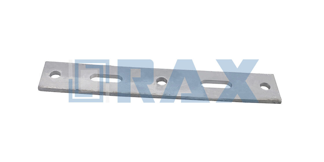
An alley arm allows utilities to navigate tight urban easements by shifting conductors to one side of the pole, but this creates a cantilever load that destroys improperly specified hardware. Our engineering team at Rax Power has found that the mechanical integrity of the entire assembly often hinges on the double arming plate, yet procurement teams frequently focus on bolt grades while ignoring the plate’s shear capacity. Get this spec wrong, and you risk the plate yielding before the brace ever transfers the load effectively.
These arms are engineered to resist distinct vertical, transverse, and longitudinal loads, but the plate itself must manage the stress concentration at the pole interface without deformation. This guide moves beyond generic descriptions to cover engineering prerequisites for plate validation, material grades for heat treatment, and the specific documentation required for supplier qualification. You get the validation criteria needed to ensure zero rejections during site testing.
Engineering Prerequisites For Plate Validation
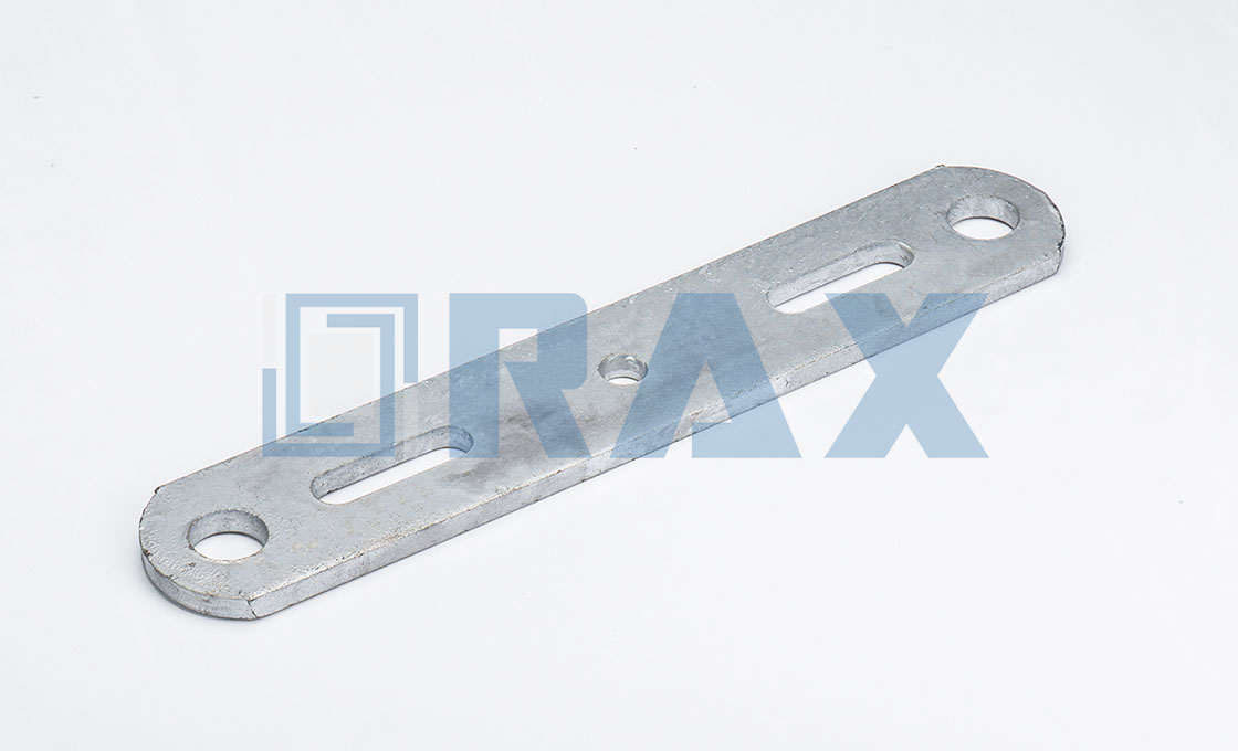
Engineering validation for pole line hardware plates isn’t just about meeting a spec sheet; it requires verifying that the component will maintain structural integrity under dynamic conductor tension, precise geometric tolerance for reliable fastener engagement, and long-term metallurgical resilience against harsh field conditions. If any of these four prerequisites fail, the entire cross-arm bracing system becomes a liability.
Structural load requirements for double arming configurations
Plates act as the primary force distribution node between conductors and support structures. When wind speeds spike or ice accumulates, mechanical tension rapidly transfers into significant shear forces. We consistently find that manufacturers relying on traditional casting methods introduce micro-porosity that dramatically lowers the yield threshold under these cyclic loads. Hot-forged microstructures eliminate that porosity, ensuring the steel undergoes controlled elastic deformation rather than permanent bending when pushed to its operational limits. In our engineering assessments, we prioritize plates designed specifically for double-arming setups because the secondary tensioning mechanism doubles the friction hold. The plate must therefore possess a higher stiffness coefficient to prevent bolt loosening over time. If the material yields even slightly, the entire tensioning sequence fails, leading to sagging conductors and costly field repairs.
Dimensional tolerance verification against IEC 120 standards
Precision isn’t a luxury in utility hardware; it is the difference between a smooth installation and a site-wide delay. Regulatory bodies mandate rigorous gauge testing precisely because misaligned bolt holes create immediate stress concentrations. When a plate deviates from its intended geometry, field crews are forced to apply excessive torque to force bolts through misaligned apertures. This artificial pre-stressing weakens the fastener threads and can fracture the surrounding metal during the initial tensioning phase. Automated CNC machining and optical measurement verify that every unit maintains strict geometric consistency. Our dedicated QC teams catch dimensional drift before it leaves the facility, guaranteeing that installers spend zero time on fabrication adjustments and full time on secure line assembly.
Galvanizing coating thickness compliance for corrosion resistance
Surface finish quality directly dictates the operational lifespan of overhead infrastructure. A common procurement pitfall involves accepting visually bright galvanization without verifying the actual metallurgical bond and depth. Thin coatings fail to protect the base steel from electrolytic corrosion, particularly in coastal or highly polluted industrial corridors where salt and acid rain accelerate metal degradation. Continuous zinc application creates a sacrificial barrier that self-heals minor scratches through cathodic protection. We enforce an internal standard that reliably shields the steel matrix for decades, prioritizing uniform adhesion across edges and corners to eliminate the weak points where corrosion typically initiates. During our routine wet-cell measurements, we verify that the coating density meets utility tender requirements before authorizing packaging.
Service arm mounting interface compatibility assessment
Utility tenders across different geographic regions demand highly specialized interface geometries. What works smoothly in Southeast Asian municipal grids may completely fail to meet the high-breaking load requirements mandated in Russian winter zones or the stringent tier-one specifications in South America. Compatibility extends beyond simple physical fitment; it requires matching the mounting hole pattern, curvature radius, and load-bearing surface area to the specific service arm design. We utilize extensive OEM/ODM capabilities to reverse-engineer and reproduce exact interface parameters from client drawings or physical samples. Before committing to bulk production, we conduct mock assembly tests to ensure zero interference during field mounting. This proactive validation prevents supply chain bottlenecks and guarantees that your procurement order aligns perfectly with regional utility standards.
Always request mill test reports alongside SGS certification documentation. Verify that the reported tensile strength matches the actual grade used in forging, as some suppliers list premium grades while shipping cast alternatives.
| Validation Parameter | Engineering Prerequisite | Testing Protocol | Compliance Standard |
|---|---|---|---|
| Material Forming Process | Hot-forged microstructure required to eliminate casting porosity and ensure superior yield strength | Metallographic analysis and tensile rupture testing | ASTM F436 / ISO 898-1 |
| Dimensional Accuracy | Strict ±1mm tolerance on plate geometry and bolt hole alignment to prevent stress concentration | Automated optical measurement and precision gauge verification | Internal CNC Quality Control / ISO 9001 |
| Corrosion Resistance | Continuous zinc coating with minimum mean thickness exceeding 85 microns to prevent base metal thinning | Coulometric and wet-cell coating thickness measurement | ISO 1461 / ASTM A153 Class C |
| Structural Load Capacity | Plate must resist plastic deformation under maximum conductor tension and wind loads | In-house progressive load testing to failure point | IEC 120 / SGS Verified |
| Surface Integrity | Galvanizing finish must not conceal micro-cracks or forging laps before assembly | Double-review inspection by dedicated QC team prior to packaging | 100% Pre-Shipment Audit / Utility Tender Specs |
Material Grades And Heat Treatment Specs
Material Grade Selection And Yield Strength
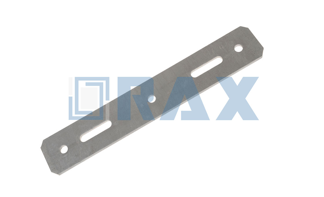
The fundamental determinant of a double arming plate’s performance is the chemical composition of the base steel. For transmission and distribution hardware, the industry standard typically pivots between low-carbon steel (equivalent to ASTM A36 or Q235) and high-strength low-alloy steel (equivalent to ASTM A572 Gr.50 or Q355). While Q235 offers a yield strength of approximately 235 MPa—sufficient for light distribution loads—projects requiring higher safety margins or extreme weather resilience increasingly demand Q355 material. The shift to Q355 provides a yield strength of 355 MPa, a roughly 50% increase in load-bearing capacity without significantly increasing the physical weight or dimensions of the plate.
Key Takeaway: Selecting Q355 (ASTM A572 Gr.50) over standard Q235 is the most cost-effective method to increase the load rating of double arming plates without altering the design geometry.
Strict adherence to metallurgical specifications dictates whether arming plates survive harsh environmental loading. Buyers must rigorously verify the chemical composition, specifically limiting impurities like Sulfur (S) and Phosphorus (P). Exceeding 0.035% or 0.040% respectively, these impurities induce brittleness, leading to catastrophic fractures under sudden impact loads or ice accumulation rather than ductile deformation. Furthermore, Silicon (Si) content must be carefully managed to regulate the Sandelin effect, which directly controls coating thickness and growth kinetics during hot-dip galvanizing. Conversely, Liquid Metal Embrittlement (LME) is a stress-dependent fracture mechanism that cannot be prevented by simple Si limitation; it requires rigorous tensile stress management and targeted mitigations specific to high-strength steel grades.
Thermal Processing: Normalizing vs. Quenching
Raw steel rolling creates internal stresses that compromise dimensional stability. Heat treatment is essential to neutralize these stresses and homogenize the grain structure. For structural plates, Normalizing (heating to roughly 900°C and air cooling) is the standard thermal cycle. This process refines the ferritic-pearlitic grain structure, ensuring the plate maintains its flatness and does not warp under the thermal shock of hot-dip galvanizing.
In high-specification scenarios, Quenching and Tempering (Q&T) may be specified to achieve tensile strengths exceeding 500 MPa. However, for standard double arming plates, Q&T is often excessive and can reduce weldability. The critical factor for procurement is ensuring the supplier performs thermal treatment prior to punching and galvanizing. Untreated or “as-rolled” steel is prone to dimensional drift, creating misalignment issues during assembly on the pole line.
Structural Integrity: Hot-Forging vs. Casting
The manufacturing method is intrinsically linked to the material’s effective strength. While casting is a low-cost alternative, it introduces inherent risks such as porosity, slag inclusions, and coarse grain structures, which act as stress concentrators. Conversely, the hot-forging process involves plastic deformation at high temperatures, aligning the metal’s grain flow to follow the contour of the component.
- Continuous Grain Flow: Forging eliminates weak points found in castings, resulting in a part that is approximately 20-30% stronger in fatigue and impact resistance.
- Toughness: Forged steel maintains ductility in sub-zero temperatures, whereas cast iron or inferior cast steel can become brittle and snap.
When evaluating technical specifications, confirmation of the forging process should be prioritized alongside the material grade. A forged Q355 plate offers superior longevity and reliability compared to a cast alternative, particularly in high-vibration environments or regions prone to heavy wind loading.

Load Capacity And Fatigue Limit Standards
Distinguishing Tensile Strength from Working Load Limits
In the procurement of overhead line hardware, a critical and frequent error is the conflation of Minimum Breaking Load (MBL) with Working Load Limit (WLL). While MBL represents the maximum stress a component can withstand before catastrophic failure in a laboratory setting, WLL is the legally and engineering-defined maximum load that should be applied during operation. Industry standards, such as those set by ISO and ASME, typically mandate a safety factor ratio between 4:1 and 5:1 for general utility hardware. This means a component with a breaking strength of 10,000 lbs must be rated for a working load of only 2,000 to 2,500 lbs. Ignoring this distinction creates unacceptable liability risks, as static loads rarely reflect the dynamic realities of field conditions, such as ice accumulation or sudden wind gusts.
Key Takeaway: Tensile strength on a datasheet is a theoretical maximum; always base procurement decisions on the Working Load Limit (WLL) which incorporates mandatory safety factors for dynamic field conditions.
The Physics of Fatigue in Overhead Infrastructure
Fatigue failure poses a more insidious threat than static overloading because it occurs at stress levels significantly below the material’s yield strength. In pole line hardware, fatigue is primarily driven by Aeolian vibration—wind-induced oscillations that cause high-frequency, low-amplitude cyclic loading. Over time, these micro-movements initiate cracks, particularly at stress concentration points like sharp corners, thread roots, or surface defects. For components such as crossarms and braces, the cumulative effect of millions of vibration cycles can lead to sudden brittle fracture without any prior plastic deformation or visible warning signs.
- Vortex Shedding: Steady winds passing through conductors and structures create alternating vortices that induce oscillation, a primary driver of fatigue in suspension hardware.
- Stress Raisers: Poor surface finish or casting porosity acts as stress amplifiers, drastically accelerating fatigue crack initiation compared to hot-forged or machined surfaces.
- Galloping: Low-frequency, high-amplitude motion caused by ice build-up adds high-magnitude dynamic stresses that test the ultimate tensile limits of anchoring systems.
Material Integrity and Fatigue Resistance
The manufacturing process plays a decisive role in defining a component’s fatigue limit. While casting is often used for complex shapes, it carries inherent risks of internal voids and irregular grain structures which serve as nucleation sites for fatigue cracks. In contrast, hot-forging aligns the metal grain flow with the contour of the part, resulting in superior fatigue resistance and tensile strength. For critical hardware applications, such as guy clamps or anchor rods, the metallurgical consistency provided by forging is essential for meeting the rigorous IEC 120 compliance standards. Furthermore, strict adherence to ISO 1461 galvanizing standards ensures that the protective coating does not introduce hydrogen embrittlement, a phenomenon that can severely compromise the fatigue life of high-strength steel fasteners.
| Product Category | Standard / Method | Load / Spec Limit | Engineering Benefit |
|---|---|---|---|
| General Pole Hardware | IEC 120 Compliance | Verified Breaking Load Limits | Ensures verified breaking loads and fatigue resistance for utility safety. |
| Steel Cross Arms | Automated QC Protocols | Strict 1mm Dimensional Tolerance | Prevents installation stress and eliminates fatigue points in structural components. |
| Critical Hardware | Hot-Forging Process | High-Breaking Load Ratings | Provides superior tensile strength compared to casting for extreme environments. |
Drawing Interpretation And Measurement Checkpoints
The Mechanics of Drawing Interpretation
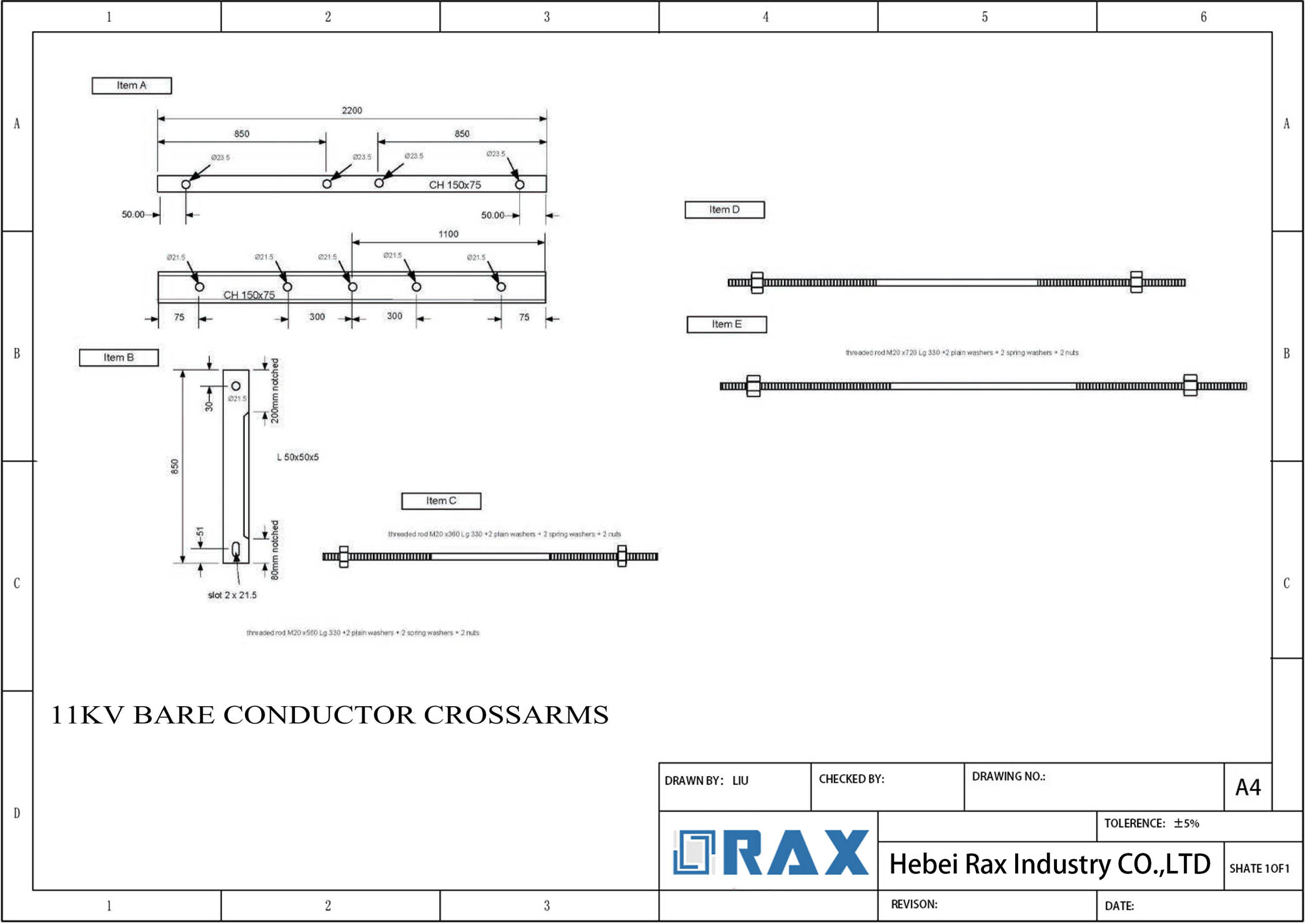
Effective drawing interpretation goes beyond reading nominal dimensions; it requires understanding the geometric relationships and tolerance stack-ups that dictate field fitment. For pole line hardware, the primary failure mode in supply chains is not gross dimensional error, but the cumulative effect of minor tolerances that prevent assembly. When reviewing technical drawings, procurement and engineering teams must prioritize the “datum” references—the theoretical exact points from which other features are measured. Misidentifying the datum can lead to acceptable parts on paper that are impossible to install in the field, particularly when dealing with curved surfaces or multiple-hole mounting interfaces.
Key Insight: A drawing specifies the “ideal” geometry, but the tolerance block defines the “acceptable” deviation. In overhead line applications, strict adherence to the tolerance block is critical to ensure interoperability with standardized cross-arms and poles.
Hole Pitch and Spacing Deviations
Hole pitch, or the center-to-center distance between mounting holes, is the most frequent source of assembly incompatibility in double arming plates and cross-arm braces. While a single hole might be within a standard diameter tolerance, its position relative to other holes can drift.
- Positional Tolerance (GD&T): Look for positional tolerance symbols (usually a circle with a cross) rather than simple plus/minus dimensions. True position tolerances define a cylindrical zone within which the axis of the hole must lie, which is more accurate than simple X/Y coordinate tolerances for ensuring bolt clearance.
- Cumulative Stack-up: In plates with multiple holes, errors can accumulate. If the drawing allows a ±0.5mm tolerance on each hole, a plate with four holes could theoretically have a total pitch error of up to 3.0mm from end to end. Verification checkpoints must measure the extreme end-to-end dimensions, not just adjacent holes.
- Clearance vs. Tapped Holes: Distinguish strictly between clearance holes (for bolts to pass through) and tapped holes. For clearance holes, the diameter must account for the galvanizing coating thickness. A hole drilled to nominal diameter before galvanizing may become undersized after coating, requiring a “drill before galvanize” instruction or an oversized tolerance on the drawing.
Curvature Alignment and Radius Metrics
For hardware designed to mount on cylindrical surfaces, such as pole bands or curved brace plates, radius verification is paramount. A flatness check is insufficient here; the part must conform to the specific curvature of the pole.
- Radius Gauge Templates: Use physical go/no-go gauge templates corresponding to the specific pole diameter (e.g., standard utility pole sizes). This checks the continuous curvature of the plate, ensuring it seats flush against the pole without gaps that could induce stress concentrations.
- Chord Length Verification: Verify the chord length (the straight-line distance between the ends of the curved plate) against the drawing. A deviation in chord length often indicates incorrect forming during the fabrication process, which will prevent the hardware from clamping the pole securely.
- Gap Measurement: When a test fit is performed, the maximum allowable gap between the hardware and the pole surface should be verified against the project specification (often limited to 1-2mm). Excessive gaps suggest a radius mismatch or poor forming consistency.

Supplier Qualification And Spec Compliance
True supplier qualification requires independent verification of third-party test authenticity and strict adherence to non-destructive coating measurement protocols to ensure structural integrity.
The Authenticity Gap in Third-Party Test Reports
A major pain point in utility procurement is the reliance on falsified or generic test reports. Many suppliers present a “Universal ISO 9001” certificate as proof of product compliance, failing to address specific mechanical load requirements or material grades. To verify legitimacy, buyers must cross-reference the report serial number directly with the certifying body’s online database, such as SGS. Furthermore, the scope of accreditation on the certificate must explicitly match the supplied product category—hardware accessories versus general steel fabrication.
Verifying Galvanizing Thickness Without Substrate Loss
Corrosion resistance is critical for overhead line hardware, but validating it often creates a conflict between quality assurance and product usability. Destructive testing methods, such as weigh-strip-weigh analysis, render the tested component useless and deplete valuable stock. Qualified suppliers must utilize Non-Destructive Testing (NDT) methods, specifically magnetic induction thickness gauges, to verify compliance with ISO 1461 standards.
Under these standards, high-quality manufacturers ensure a mean coating thickness exceeding 85 microns. When auditing a supplier, inspectors should verify that the measuring equipment is calibrated and that the sampling plan covers critical stress points—such as the curved sections of guy clamps or the inner threads of eye bolts—where coating uniformity is hardest to maintain. This approach confirms corrosion protection without compromising the substrate of the hardware.
Compliance Assessment Protocols
To effectively filter suppliers, procurement teams should implement a qualification protocol that validates the physical reality of the reported data. This involves moving beyond paperwork to on-site or video-supervised verification of the testing laboratory.
- Certificate Traceability: Verify the validity of all SGS or third-party mill test reports by checking the issuing authority’s official database for report numbers and dates.
- NDT Calibration Checks: Require documentation proving that magnetic thickness gauges are calibrated to national standards to ensure the 85-micron galvanizing claim is accurate and not a result of instrument drift.
- Substrate Integrity Preservation: Confirm that the quality control process utilizes non-destructive verification methods for 100% of outgoing batches, ensuring that no parts are thinned or weakened by “test cuts” during the inspection phase.
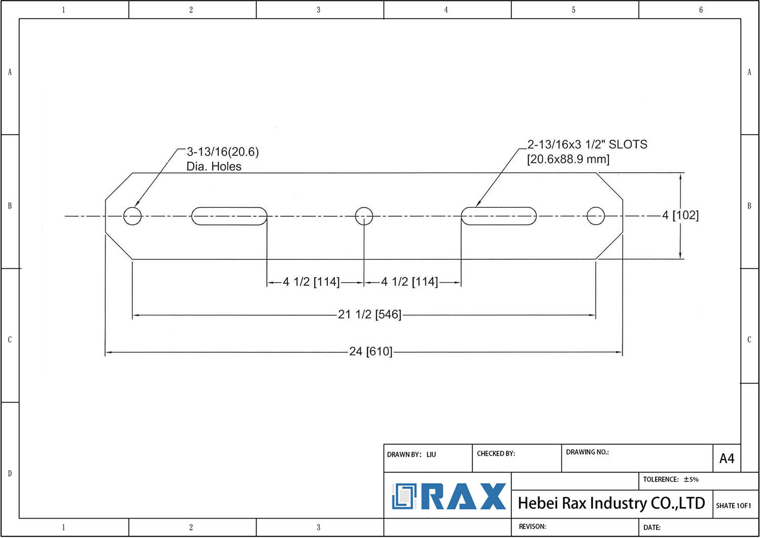
Integration Compatibility With Arming Mechanisms
Bolt Shear Capacity vs. Plate Bearing Strength
The mechanical integrity of a double arming assembly relies heavily on the relationship between the fastener’s shear capacity and the plate’s bearing resistance. A common failure mode in the field involves bolt elongation or hole deformation when these two elements are mismatched. When selecting hardware, the plate’s material hardness must be sufficient to prevent the bolt shank from wallowing out the hole under high wind or ice loads. Generally, industry-grade double arming bolts manufactured through hot-forging offer superior grain structure strength compared to cast alternatives, ensuring that the failure point remains predictable and within the safety margin of the assembly rather than resulting in a sudden, catastrophic shear of the fastener.
Compatibility checks must verify that the hole diameter allows for the specified bolt size without excessive play. Excessive clearance reduces the shear capacity of the assembly by altering the load path from a pure shear force to a bending moment on the bolt. For high-voltage applications where double arming configurations are used to support heavier transformers or longer crossarms, specifying plates with closer dimensional tolerances is critical to maintain the designed load distribution across both bolts.
Geometric Alignment and Pole Splitting Mitigation
Pole splitting remains a critical risk during installation, particularly with steel or concrete poles where high clamping forces are applied. The curvature radius of the arming plate must closely match the nominal diameter of the pole. If the gap between the plate and the pole surface exceeds 2mm to 3mm before tightening, the concentrated pressure from the U-bolt or machine bolt can exceed the hoop stress of the pole material, causing longitudinal cracks.
High-precision manufacturing utilizing automated stamping or bending processes is required to ensure consistent curvature across a batch of plates. Variability in plate radius not only jeopardizes the pole but also misaligns the mounting angles, leading to uneven stress distribution on the crossarm. For wood poles, the issue is compounded by the compressibility of the material; plates must sit flush to prevent crushing the wood fibers, which would loosen the grip over time due to creep and shrinkage.
Zinc Coating Tolerances and Thread Fit
While hot-dip galvanizing compliant with ISO 1461 is essential for corrosion resistance, it introduces a variable that often trips up integration: coating buildup. A mean coating thickness exceeding 85 microns is standard for longevity, but this layer adds dimensional volume to both the threaded holes and the mating bolts. If the internal threads of a plate or the external threads of a bolt are not tapped or cut with allowance for this zinc layer, cross-threading or galling occurs during field assembly.
Compatibility protocols must account for this by ensuring that either the fasteners are tapped after galvanizing or that the design clearance accommodates the added thickness. Ignoring this factor leads to installation crews forcing bolts, which damages the protective zinc layer and creates immediate corrosion pathways. Furthermore, the stiffness of the zinc coating can affect the friction characteristics of the joint, potentially impacting the torque-tension relationship required to secure the arming mechanism effectively.
Bracing Mechanism Integration
Integration extends beyond the primary pole attachment to the interface with alley arms and lateral bracing. Alley arms, often mounted to one side of the pole, require rigid bracing to ensure proper alignment and prevent bending under load. These braces typically mount at a 45-degree angle and attach to the side of the arm via machine bolts.
- Hole Alignment Accuracy: The position of the bolt holes on the arming plate must align perfectly with the standardized bolting patterns of the alley arm and the brace. Misalignment here induces torsional stress on the crossarm rather than pure vertical support.
- Structural Reinforcement: The arming plate acts as a transfer point, distributing the load from the lateral brace into the main pole structure. Inadequate stiffness in the plate at this junction can lead to deflection, causing the insulator strings to drift out of phase.
- Step Integration: Some configurations incorporate welded lineman steps on the brace assembly. The arming plate must not interfere with the safe operation of these steps, requiring careful spatial planning of the hardware interface to ensure climbing clearance is maintained.
Final Procurement Validation And Documentation
Executive Summary: Final procurement is not just about payment; it is about verifying that the technical data on paper matches the physical reality in the crate. Always cross-reference SGS certificates with physical heat numbers, demand IEC 120 gauge logs for dimensional proof, and secure explicit tooling ownership clauses before release.
Verifying SGS Certification and Mill Test Reports
For high-load transmission hardware, accepting a generic “SGS Certified” PDF is insufficient. You must verify the traceability of the certification against the specific batch numbers shipped. A Mill Test Report (MTR) is useless if it cannot be linked to the heat code stamped on the actual hardware. When reviewing documentation, ensure the MTR lists the specific chemical composition and mechanical yield properties matching your order specifications—typically Q235 or Q345 steel grades for crossarm assemblies. We ensure that every shipment is accompanied by batch-specific SGS verification, confirming that the chemical analysis and tensile strength documented in the report physically correspond to the hardware in that specific container.
Additionally, verify that the galvanization compliance (ISO 1461 or ASTM A153) is listed on the MTR. The report should state the average coating thickness, which must exceed 85 microns to guarantee long-term corrosion resistance. If the documentation lacks these specific micro-measurements, reject the batch. In our facility, we maintain a 1:1 audit trail where every packaged unit can be traced back to its specific galvanizing dip and raw material heat number, eliminating the risk of substitution.
In-House Gauge Testing Documentation Review
Visual inspection is subjective; gauge testing is objective. Before signing off on a production run, demand the raw data from the factory’s in-house gauge testing process. This documentation should confirm that critical dimensions—such as bolt-hole diameter, hole spacing, and overall length—adhere to IEC 120 standards. Specifically, look for variance reports. If a factory claims “zero defects,” they likely aren’t measuring strictly enough. You want to see proof that out-of-tolerance items were identified and culled.
For critical components like steel cross arms and alley arms, a strict 1mm dimensional tolerance is often required to ensure proper fitment with existing infrastructure. Our documentation review process includes the automated gauge logs from our production line, providing a digital footprint of every unit’s dimensions. When reviewing these documents, check that the “Go/No-Go” gauge results were recorded for random samples throughout the production run, not just at the start. This consistency check prevents “tolerance drift” that often occurs in long production shifts where tooling wear starts to affect hole sizing.
Custom Manufacturing Agreement and Tooling Transfer Terms
When engaging in OEM/ODM for specialized pole line hardware, the commercial agreement must address intellectual property and physical asset ownership. If you are funding custom mold development for unique fittings, the contract must explicitly state that the tooling belongs to you, not the manufacturer. This “Tooling Transfer” clause is critical; it ensures that if you switch suppliers, you can legally take your molds with you rather than having your inventory held hostage.
- Ownership Clauses: Ensure the contract defines “Paid Tooling” as client property, distinct from standard factory tooling.
- Storage Fees: Define who pays for mold storage during non-production periods. We offer transparent storage terms, ensuring your molds are maintained in climate-controlled conditions without hidden fees.
- Modification Rights: Retain the right to approve any modifications to the mold that might affect the interchangeability of parts.
- Life-of-Tool Terms: Agree on a shot-life guarantee (e.g., the mold is good for 50,000 cycles) to prevent being charged for premature repairs.
Pre-Shipment Quality Inspection Checklist Completion
The Pre-Shipment Inspection (PSI) checklist is your final firewall. It should not be a simple “Pass/Fail” checkbox but a detailed report covering visual, dimensional, and mechanical attributes. Do not accept a checklist signed by a packer; it must be countersigned by a dedicated Quality Control (QC) supervisor. The checklist must verify that the galvanizing finish is smooth and free of ash or drips, and that the torque markings on bolts are clear.
At Rax Power, we enforce a “Double-Review Process” where 100% of products are inspected twice before packaging. The final PSI document you receive should reference this rigor, including load test results for a percentage of the batch (e.g., proof load testing per IEC standards). If the PSI checklist lacks data points—such as actual micrometer readings or coating thickness samples—do not authorize the shipment. This document is your legal advantage should defects be discovered upon arrival at the job site.
Never release the final balance payment based solely on photos. Require the physical or digitally scanned original PSI checklist with signature authorization.
Conclusion
Validating double arming plates requires much more than just checking dimensions. You must rigorously verify structural load requirements against IEC 120 standards while simultaneously confirming galvanizing thickness for optimal corrosion resistance. Material grades dictate fatigue limits, so do not overlook heat treatment specs. Precision here prevents catastrophic field failures later.
Treat your suppliers like engineering partners rather than simple vendors. Always request the mill test reports and SGS certifications before approving any final procurement documentation. Our engineering team at Rax Power reviews technical drawings to ensure ISO 1461 compliance and forging precision. We can audit your current configurations or help verify new specs without any obligation.
Frequently Asked Questions
Does bolt grade or plate shear matter more?
Both components require balanced mechanical ratings to prevent premature failure under dynamic wind loads. Focusing solely on high-grade bolts while ignoring the plate’s shear capacity creates a weak link in the assembly. The double arming plate must distribute tension evenly across the pole without deforming. Matching bolt tensile strength with plate yield strength ensures reliable long-term performance.
How do pole materials impact arming plates?
Wooden poles require flexible clamping mechanisms to accommodate natural expansion and contraction over time. Concrete or composite poles demand rigid interfaces with precise curvature matching to prevent stress concentration. Engineers must select plate profiles that align with the specific diameter and material properties of the utility infrastructure. Mismatched interfaces often lead to accelerated corrosion or mechanical slippage.
Which standards govern overhead line hardware testing?
International electrical engineering bodies establish comprehensive testing protocols for mechanical strength and environmental resistance. Manufacturers typically validate products against recognized frameworks covering load capacity, corrosion resistance, and fatigue performance. Compliance with these standards guarantees that hardware will perform reliably under extreme operational conditions. Utility projects frequently mandate specific standard certifications during the tender evaluation phase.
How to verify high breaking load claims?
Buyers should request independent third-party test reports rather than relying on vendor marketing statements. Reputable manufacturers conduct rigorous in-house load testing per established international electrical standards. These documents must clearly state the testing methodology, maximum applied force, and failure mode. Validated data provides the necessary confidence for utility procurement compliance.