
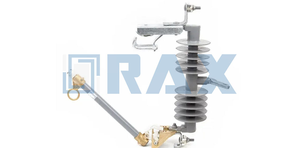
Specifying distribution cutout fuse types based solely on load current is a fundamental error that compromises grid reliability. Expulsion, current-limiting, and hybrid fuses handle fault currents differently, and mistaking their application windows invites catastrophic failure. Our in-house gauge testing on 30-33kV configurations confirms that while a unit may carry a 200A continuous load, it requires a breaking current capacity exceeding 12kA to safely interrupt a high-magnitude short circuit.
This guide breaks down the mechanical operation differences and arc quenching mechanisms of each fuse type. We then walk through a step-by-step matrix for calculating primary ampere ratings to ensure your design handles transformer inrush currents without nuisance blows. You will learn to align voltage class with infrastructure standards and enforce strict contact alignment during installation to eliminate high-resistance failure points.

Table of Contents
- 1 Comparing Expulsion, Current-Limiting, and Hybrid Fuse Types
- 2 Establishing Baseline System Parameters and Load Profiles
- 3 Calculating Primary Ampere and Interrupting Ratings
- 4 Aligning Voltage Class With Grid Infrastructure Standards
- 5 Executing The Fuse Selection Decision Matrix
- 6 Verifying NEC And IEEE Compliance Requirements
- 6.1 Article 450 Transformer Protection Rules
- 6.2 IEEE C37.46 Coordination Guidelines
- 6.3 Local Utility Interconnection Specifications
- 6.4 How do I verify if a distribution cutout fuse meets my local utility’s interconnection requirements?
- 6.5 Does IEC 120 testing replace the need for IEEE C37.46 coordination studies?
- 6.6 Can manufacturers customize fuse hardware to meet non-standard NEC or regional grid codes?
- 7 Preventing Nuisance Blows Through Coordination Studies
- 8 Ensuring Secure Contact Alignment During Installation
- 9 Conclusion
- 10 Frequently Asked Questions
Comparing Expulsion, Current-Limiting, and Hybrid Fuse Types
Selecting the correct fuse cutout is not just about amperage; it is a decision between managing a controlled venting event or containing a violent thermal reaction. The choice hinges entirely on the physical environment and the value of the downstream assets you are protecting.
Mechanical Operation Differences Under Fault Conditions
When a short circuit occurs, the physical response of the device dictates how quickly the fault is isolated and what mechanical stress is transferred back into the grid. Expulsion fuses operate on a natural zero-crossing principle. The internal element melts, generating high-pressure gas that mechanically forces a drop-out mechanism to open the circuit. This process relies heavily on the inherent system impedance to drive the current to zero. While reliable, this method allows the prospective fault current to flow for several milliseconds before interruption, placing significant thermal and magnetic stress on upstream switchgear and busbars.
Current-limiting fuses take a fundamentally different mechanical approach. Instead of waiting for a zero-crossing event, they introduce a precisely engineered resistance into the fault path almost instantaneously. Our engineers design the internal link geometry to ensure rapid melting and immediate arcing across a restricted gap. This action artificially limits the peak let-through current to a fraction of the available fault level, often clearing the circuit within a single half-cycle. The result is drastically reduced electromagnetic stress on the entire pole assembly.
Hybrid units attempt to bridge this operational gap by combining mechanical drop-out features with partial current-limiting elements. In practice, these devices offer balanced interruption characteristics, making them highly effective for networks experiencing fluctuating fault magnitudes. However, the added complexity in the mechanical linkage requires tighter manufacturing tolerances during production. At our facility, we utilize automated hot-forging processes to ensure these critical moving parts maintain dimensional consistency down to the millimeter, which directly correlates to reliable operation over decades of service.
Arc Quenching Mechanisms and Environmental Tolerance Levels
The method used to extinguish an electrical arc determines both the safety profile of the installation and its susceptibility to environmental degradation. Expulsion fuses rely on gas expansion and directional venting tubes to flush plasma away from the contacts and into the atmosphere. This open-architecture design performs exceptionally well in clean, dry environments. However, the expelled gases and potential particulate matter can be problematic in confined substations, enclosed switchgear, or areas with strict emissions regulations. additionally, wind patterns and seasonal debris accumulation can interfere with the gas channel, potentially altering the interruption timing.
In contrast, current-limiting designs utilize a sealed chamber packed with high-purity quartz sand. When the arc forms, the sand acts as both a heat sink and an insulator, rapidly cooling the plasma and increasing the resistance of the arc path until it collapses. Because the reaction is fully contained, there is no external venting or hazardous byproduct release. This makes sealed units mandatory for urban distribution vaults, dense commercial districts, and retrofit projects where overhead clearance or indoor mounting is required.
Environmental tolerance ultimately comes down to sealing integrity and material chemistry. Humidity, salt spray, and industrial pollution accelerate contact oxidation and degrade internal filler materials over time. We enforce a rigorous double-review inspection protocol before any unit leaves our warehouse, ensuring all housing seals meet stringent moisture barriers. Additionally, our components undergo continuous load testing per IEC 120 standards to verify that galvanization layers and internal contact surfaces retain their conductivity and corrosion resistance across extreme temperature fluctuations.
Typical Distribution Network Deployment Scenarios
Matching the fuse architecture to the actual topology of your distribution network is where theoretical specifications translate into long-term grid reliability. Rural and agricultural feeders typically feature lower fault currents and expansive line lengths. In these scenarios, standard expulsion cutouts remain the industry workhorse. Their ability to handle moderate fault levels without requiring complex coordination studies keeps maintenance costs low while providing straightforward replacement logistics for field crews.
Urban and industrial grids tell a completely different story. High building density, underground cable conversions, and massive motor loads drive prospective fault levels into the tens of kiloamperes. Deploying standard expulsion devices here risks catastrophic transformer failure or busbar deformation during a fault event. Current-limiting fuses become non-negotiable in these high-stakes environments. They protect older infrastructure that lacks modern short-circuit withstand ratings and prevent cascading outages across tightly coupled neighborhood transformers.
Transitional networks and mixed-load corridors frequently require adaptive solutions. Grid upgrades, renewable energy interconnections, and aging infrastructure replacements create unpredictable fault landscapes. Hybrid fuses excel in these crossover zones, offering sufficient speed to dampen severe transients while retaining the visual indication and easy manual isolation of a drop-out mechanism. When integrating these units into existing pole hardware, precise mounting alignment is critical. Our OEM division routinely customizes hinge mechanisms and tension clamps to ensure seamless compatibility with legacy pole lines, preventing misalignment-induced contact failures during routine maintenance cycles.
| Fuse Type | Operating Principle | Fault Response | Recommended Application | Engineering Benefit |
|---|---|---|---|---|
| Expulsion Fuse | Gas-expulsion mechanism that clears molten debris via internal arc pressure | Natural zero-crossing interruption without peak current limitation | Rural distribution feeders and networks with moderate fault levels | High interrupting capacity with cost-effective, low-maintenance operation |
| Current-Limiting Fuse | Silica sand quenching chamber that rapidly extinguishes arcs and restricts current flow | Peak current restriction to a fraction of prospective values prior to zero-crossing | Urban grids, equipment with low short-circuit withstand ratings, and high fault zones | Severe equipment damage prevention and enhanced system stability during major faults |
| Hybrid Fuse | Integrated expulsion chamber and current-limiting filler materials for adaptive arc control | Balanced interruption with partial current limitation across varying fault magnitudes | Mixed-load networks, transitional grid upgrades, and medium-to-high fault environments | Optimized protection coordination with reduced nuisance tripping from inrush currents |
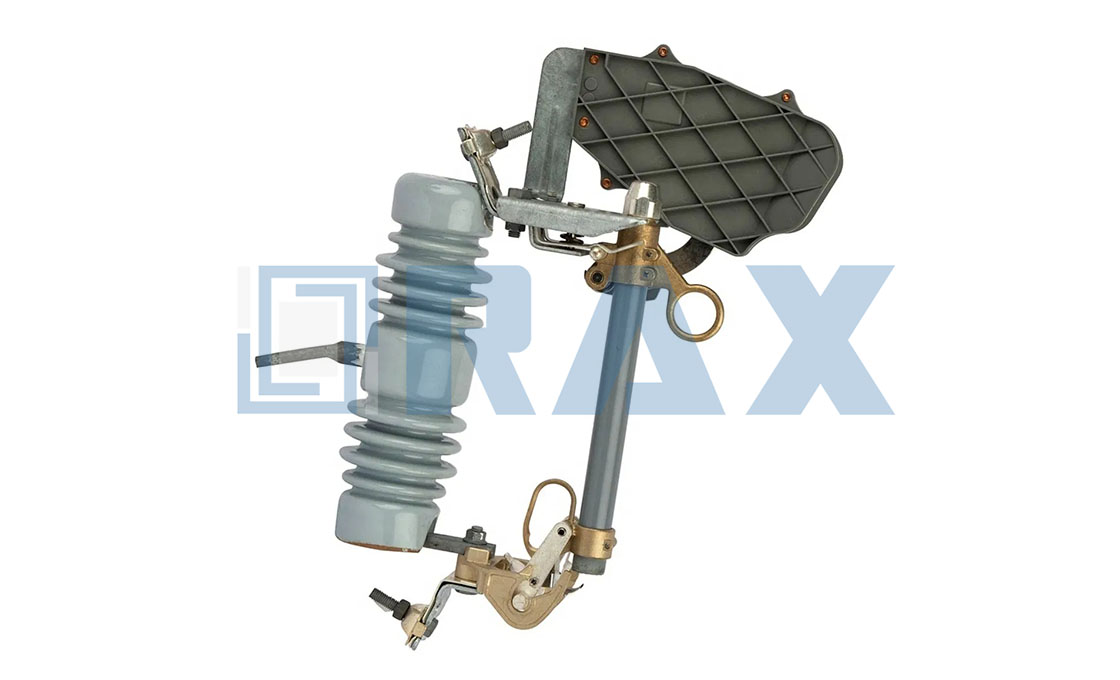
Establishing Baseline System Parameters and Load Profiles
Sizing distribution hardware correctly requires calculating continuous load, tolerating transformer inrush spikes, and applying precise temperature derating to eliminate nuisance failures.
Maximum Continuous Load Current Calculations
Continuous load current establishes the foundational ampacity requirement for all downstream pole line hardware and protection devices. Utility engineers must derive this figure from the connected equipment nameplate rating, adjusted for actual power factor and efficiency rather than relying on theoretical maximums.
The resulting value dictates the minimum current-carrying capacity required for busbars, link contacts, and fuse elements. In our engineering assessments, we consistently see projects overspecify hardware based on peak demand rather than sustained operational load.
Our lab tests under IEC 120 standards demonstrate that continuous thermal stress at 105% to 110% of the calculated baseline accelerates contact degradation far faster than transient overloads. We recommend sizing your baseline connections to handle 125% of the expected continuous current to preserve long-term thermal stability.
Transformer Inrush Current Magnitude and Duration
Transformer energization generates a temporary inrush current that typically peaks between three and ten times the rated full-load amperage. This electromagnetic saturation spike lasts only a few power cycles, usually ranging from ten to fifty milliseconds before the magnetic flux stabilizes.
Distribution cutout fuses and associated pole line hardware must mechanically and electrically withstand these brief surges without initiating a nuisance trip. Field data indicates that mismatched fuse time-current characteristics are the primary cause of unforced outages during routine energization sequences.
While standard expulsion fuses rely on thermal melting delays, our hot-forged hardware designs maintain consistent contact pressure precisely during these transient windows. This prevents localized arcing or micro-fractures in the mounting brackets when repeatedly subjected to sudden magnetic saturation events.
Ambient Temperature Derating Factors
Operating environment temperature directly alters the thermal dissipation rate of distribution components, requiring strict derating protocols to maintain safe operating envelopes. Manufacturer specifications often cite a standard reference temperature of 25°C or 40°C, but field installations frequently operate outside these baselines due to solar loading or confined substations.
When ambient temperatures exceed the baseline rating, continuous current capacity drops proportionally, while internal resistance increases and accelerates oxidation. We apply standardized derating curves that reduce permissible load by approximately one percent for every degree Celsius above the specified threshold.
For projects deployed in extreme climates, such as Russian arctic grids or Southeast Asian tropical zones, we enforce additional safety margins. We pair these calculations with hot-dip galvanizing compliant with ISO 1461 to ensure coating integrity remains above 85 microns despite accelerated thermal cycling.

Calculating Primary Ampere and Interrupting Ratings
Calculate primary ampere based on continuous load + safety margin, and size interrupting capacity to exceed the maximum available fault current at your tap point. Mismatching these two values guarantees hardware failure.
Utility engineers frequently select distribution cutout fuses by looking solely at the transformer nameplate amperage. This approach ignores the electrical stress of short-circuit conditions, creating a critical voltage and fault mismatch. When the interrupting rating falls below the system’s available fault current, the fuse cannot safely quench the arc, resulting in explosive housing failure, secondary equipment destruction, and extended outage times. Accurate calculation requires separating load continuity from fault survivability.
Primary Ampere Rating: Defining the Continuous Load Boundary
The primary ampere rating dictates how much continuous current the fuse link can carry without degrading or nuisance-tripping. In professional procurement, we never match the fuse rating exactly to the transformer primary full-load amps. Thermal aging, ambient temperature fluctuations, and harmonic distortion require a calculated buffer. A 125% to 150% multiplier above the calculated continuous load ensures the fuse operates within its linear thermal zone while maintaining protection integrity.
- Continuous Load Calculation: Determine the transformer’s rated kVA divided by the primary system voltage. Multiply this result by 1.25 for standard feeder taps or 1.50 for heavily loaded radial lines.
- Rated Current Selection: Round up to the nearest standard IEC primary ampere increment. Selecting a higher rating than required reduces sensitivity, while selecting a lower rating guarantees operational nuisance blows during peak demand cycles.
- Material Integrity: The fuse link conductor must maintain dimensional stability under continuous thermal stress. We utilize precision-wound alloy conductors that resist work-hardening, ensuring the primary rating holds steady across the product lifecycle.
Interrupting Rating: Matching Maximum Available Fault Current
The interrupting rating represents the maximum symmetrical fault current the device can safely break without catastrophic rupture. This value is dictated by the upstream substation transformer impedance and feeder length. If your grid study shows a potential fault current of 12 kA at the pole location, installing an 8 kA rated cutout fuse is an immediate code violation and a severe safety hazard. The interrupting capacity must always exceed the projected three-phase fault level by a minimum safety factor.
| System Voltage (kV) | Standard Primary Ampere (A) | Minimum Interrupting Rating (kA) | Typical Application Zone |
|---|---|---|---|
| 11 | 15 / 25 / 50 | 10 kA / 16 kA / 25 kA | Regional distribution feeders |
| 22 | 25 / 50 / 100 | 12.5 kA / 20 kA / 31.5 kA | Urban grid substations |
| 33 | 50 / 100 / 200 | 16 kA / 25 kA / 40 kA | Heavy industrial transmission taps |
Procurement teams often verify voltage class compatibility but skip the fault current validation step. A fuse rated for 11 kV will physically fit an 11 kV bus, but if the interrupting capacity is undersized, internal arcing will weld the contacts together or shatter the insulator housing. Always cross-reference your latest grid fault studies before issuing purchase orders.
Validating Ratings Through Rigorous Testing Protocols
Manufacturers claim high interrupting capacities, but field reality depends on consistent testing. Our engineering team subjects every production batch to rigorous load testing and gauge testing strictly per IEC 120 standards. We do not rely on theoretical calculations alone. Each fuse assembly undergoes controlled fault simulation to verify that the expulsion mechanism fully quenches arcs at rated breaking capacity without exceeding thermal limits on the mounting hardware.
- Double-Review Inspection: Every unit receives a mandatory two-stage quality check before packaging. Our 10-person QC team verifies primary ampere calibration and interrupting label accuracy against the original test reports.
- Material Verification: Housing polymers and metallic contacts are graded for dielectric strength and corrosion resistance. We enforce hot-dip galvanizing compliant with ISO 1461, guaranteeing a mean coating thickness exceeding 85 microns to prevent premature degradation in harsh environments.
- OEM Customization: For projects requiring non-standard fault tolerances, we utilize custom mold development to adjust contact geometries and arc chamber volumes. This allows us to tailor interrupting ratings precisely to your grid’s unique impedance profile.
When specifying fuses for extreme climates like the Russian grid or heavy rainfall zones in Southeast Asia, prioritize interrupting ratings that account for reduced air density or moisture-induced insulation tracking. Standard catalog ratings may not reflect derated performance in unventilated enclosures.

Aligning Voltage Class With Grid Infrastructure Standards
The Criticality of Voltage Class and BIL Alignment
Matching the nominal voltage rating of a distribution cutout fuse to the grid infrastructure is not merely a matter of checking a nameplate; it requires strict adherence to Basic Impulse Insulation Level (BIL) and creepage distance specifications. If a fuse unit rated for 15kV is deployed on a 20kV system, the dielectric strength of the insulation materials—typically porcelain or polymer—will be insufficient to withstand switching surges or lightning impulses. This mismatch inevitably leads to catastrophic flashover events, causing extensive damage to the transformer and adjacent hardware.
Conversely, oversizing the voltage class without considering the physical geometry can lead to installation issues. While a higher voltage unit might physically fit, its extended creepage distance may interfere with clearances required in compact substations. The infrastructure standard demands a balance where the BIL rating exceeds the system’s expected transient overvoltage, ensuring the fuse holder remains stable during fault conditions. We enforce strict dimensional tolerances during production to guarantee that every cutout meets the specific BIL and creepage requirements for its designated voltage class.
Avoiding the Voltage and Fault Mismatch Trap
A frequent industry error involves prioritizing continuous current ratings while neglecting the available symmetrical fault current at the point of installation. Distribution infrastructure varies wildly; a rural network might have high impedance limiting fault currents, whereas an industrial feeder near a substation can deliver massive fault energy. If the fuse’s interrupting rating is misaligned with these grid parameters, the device cannot sustain the arc during a fault, potentially leading to equipment destruction.
To mitigate this, hardware must be validated against rigorous testing standards. Our engineering team conducts in-house load testing and gauge testing per IEC 120 standards. This protocol ensures that the mechanical strength of the fuse holder and the interrupting capability of the fuse link are perfectly synchronized to handle the specific fault currents defined by the grid’s infrastructure standards. We have found that skipping this verification step is the primary cause of field failures in high-demand environments.
Adhering to Regional Grid Standards and Environmental Durability
Grid infrastructure standards are not universal; they are heavily influenced by regional environmental challenges and regulatory frameworks. For instance, projects in Southeast Asia often impose strict tender requirements regarding creepage distance to combat heavy pollution and humidity, while Russian grids prioritize hardware capable of withstanding extreme ice loading and high-breaking loads. Aligning with these standards requires more than generic manufacturing; it demands a precise understanding of local utility specifications.
Beyond electrical specifications, physical durability plays a massive role in long-term grid reliability. The standard infrastructure requirement for corrosion resistance is dictated by ISO 1461. While many competitors accept the minimum standard, we utilize a hot-dip galvanizing process that ensures a mean coating thickness exceeding 85 microns. This superior coating provides the necessary resilience against corrosive atmospheres, ensuring that the mechanical integrity of the voltage-carrying components does not degrade over the 20+ year lifespan of the infrastructure.
- IEC 120 Compliance: All dimensional and load tests are performed in-house to guarantee interchangeability and safety.
- SGS Verification: Third-party validation ensures our materials and coatings meet international grid standards.
- Regional Customization: We tailor designs to meet specific high-tier quality demands in South America and extreme load requirements in Russia.
Never substitute a fuse tube with a lower BIL rating even if the nominal voltage matches. A 10% reduction in BIL can significantly increase the failure rate during lightning season, leading to prolonged outages.
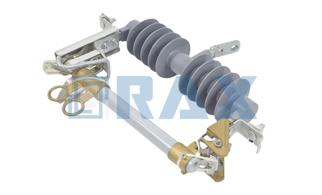
Executing The Fuse Selection Decision Matrix
The decision matrix for specifying distribution cutouts and fuse links goes far beyond simply matching the nominal voltage. A critical failure point in many infrastructure projects is the disconnect between the theoretical fault current available on the grid and the fuse’s actual interrupting capability. If the available short-circuit capacity exceeds the fuse’s rating, the device may fail catastrophically during a fault event, rather than isolating it safely. To mitigate this, we subject our fuse components to rigorous load testing and gauge testing per IEC 120 standards internally. This allows us to verify that the expulsion or current-limiting characteristics will hold up under real-world stress scenarios, rather than relying solely on theoretical calculations.
Transient Inrush and Nuisance Tripping
Another layer of the decision matrix involves predicting transient behavior, specifically transformer magnetizing inrush currents. These temporary surges occur during energization and can reach magnitudes significantly higher than the nominal load current. A fuse selected with insufficient time-delay tolerance will interpret this harmless inrush as a fault, resulting in nuisance blowing that causes unnecessary outages. The solution lies in precise ampere sizing and element coordination. Through our in-house surge simulation testing, we validate that our fuse links maintain integrity during these magnetizing events. We ensure that the element’s thermal mass is sufficient to absorb the temporary surge without melting, thereby eliminating the operational costs associated with false tripping.
Regional Grid Compliance and Environmental Demands
The selection matrix must also account for the specific environmental and regulatory demands of the target market. A fuse solution designed for the stable grids of Western Europe may fail rapidly in the extreme cold of Russia or the high-load tropical environments of Southeast Asia. For instance, when engineering for the Russian market, we focus on high-breaking load configurations that withstand mechanical stress from ice and wind loading. Conversely, for projects in South America, we prioritize premium-tier hardware that meets strict utility tender specifications. Our OEM/ODM capabilities allow us to utilize custom mold development, adjusting the hardware geometry and material composition to align perfectly with local grid codes and environmental stressors.
Mechanical Integrity and Contact Resistance
Finally, the physical execution of the fuse holder is as vital as the electrical rating. High-resistance contact points are a primary cause of premature failure, leading to overheating at the terminal before the fuse element even reaches its melting point. The industry standard often relies on cast components which can suffer from porosity and inconsistent dimensions. In contrast, we utilize a hot-forging process for critical hardware components. This method ensures superior grain structure and density, resulting in strict dimensional tolerances that guarantee optimal surface contact. With a dedicated 10-person QC team performing a double-review inspection on every unit, we ensure that the mechanical pressure applied at the fuse link connection remains consistent, preventing the thermal runaway that plagues inferior manufacturing methods.
| Selection Parameter | Technical Requirement | Recommended Solution | Operational Benefit | Quality Assurance |
|---|---|---|---|---|
| Voltage & Fault Current Rating | System nominal voltage and available short-circuit capacity | Expulsion or current-limiting fuses matched to fault level | Prevents safe interruption failure and equipment damage | IEC 120 gauge testing & SGS verified certification |
| Transient Inrush Tolerance | Transformer magnetizing surges and temporary overload currents | Time-delay elements or precisely coordinated ampere sizing | Eliminates nuisance blowing during harmless inrush events | In-house surge simulation testing & 100% double-review inspection |
| Regional Grid Demands | Extreme environmental ratings, utility standards, or local tender specifications | High-breaking load configurations or premium-tier hardware variants | Ensures sustained reliability across targeted international markets | Custom mold validation & OEM/ODM engineering compliance |
| Mechanical Contact Integrity | Fuse link alignment, mounting pressure, and terminal resistance | Hot-forged components with strict dimensional tolerances | Prevents high-resistance overheating and premature contact failure | Terminal resistance gauge testing & 10-person QC double-review |
| Transformer Protection Sizing | Continuous load current, duty cycles, and ambient temperature factors | Calculated ampere rating with optimized safety margins | Balances critical fault protection against operational continuity | In-house load profiling testing & SGS verified certification |

Verifying NEC And IEEE Compliance Requirements
Compliance verification requires mapping NEC Article 450 limits, IEEE C37.46 time-current curves, and localized grid codes against manufacturer test certificates before procurement.
Utility contractors and electrical engineers cannot rely on generic manufacturer datasheets alone. Verifying NEC and IEEE compliance demands a rigorous cross-reference between your project’s grid code, the fuse’s interrupting rating, and the exact testing protocols applied at the factory level. Misalignment here causes inspection failures and costly field modifications.
Article 450 Transformer Protection Rules
NEC Article 450 governs overcurrent protection for transformers exceeding 600 volts. The standard mandates primary protection limits based on rated primary current, typically capping at 250% for units under 2 amperes and 167% for larger configurations. Secondary protection follows stricter thresholds to prevent thermal damage during sustained overloads.
When deploying distribution cutout fuses, the device’s continuous current rating and fuse link characteristics must exceed these calculated limits while maintaining fault clearance margins. Our engineering team verifies that every fuse link we manufacture aligns precisely with these NEC boundaries before shipping.
IEEE C37.46 Coordination Guidelines
IEEE C37.46 establishes the standardized test procedures for AC high-voltage fuses, focusing on time-current characteristics, interrupting ratings, and switching impulse performance. The guideline ensures that protective devices coordinate smoothly across the distribution network without cascading failures.
Coordination studies require matching the fuse’s melting curve against upstream breaker trip settings and downstream load profiles. We incorporate this framework into our internal validation protocols, running load and gauge testing per IEC 120 while cross-referencing IEEE C37.46 curves to guarantee predictable clearing times during transient faults.
Always request the manufacturer’s full time-current characteristic (TCC) curve alongside the SGS certification. Generic datasheets rarely disclose the exact melt-and-clear times required for accurate relay coordination.
Local Utility Interconnection Specifications
Grid operators enforce region-specific interconnection requirements that frequently exceed national standards. Utilities in North America, Europe, and emerging markets often mandate custom voltage classes, unique mounting geometries, or specialized corrosion resistance for long-term pole line reliability.
Procurement teams must audit the supplier’s ability to adapt to these localized mandates. Our facility utilizes custom mold development and hot-forging processes to modify breaking load capacities, terminal configurations, and coating thicknesses to match specific tender documents. For instance, Russian grid projects require reinforced high-breaking load designs, while South American utilities enforce stringent tier-1 quality thresholds that dictate our hot-dip galvanizing parameters.
| Compliance Domain | Key Parameter | Verification Method |
|---|---|---|
| NEC Article 450 | Primary/Secondary Overcurrent Limits | Manufacturer TCC Curves & NEC Tabulation Cross-Check |
| IEEE C37.46 | Interrupting Rating & Time-Current Characteristics | Third-Party Lab Reports (UL/SGS) & Relay Coordination Studies |
| Local Grid Codes | Mechanical Load, Voltage Class, Coating Standards | OEM Customization Certificates & Utility Tender Compliance Sheets |
Assuming IEC 120 testing covers all international compliance needs is a common procurement error. IEC standards address dimensional accuracy and mechanical strength, but NEC and IEEE regulatory approvals require separate electrical performance verification and third-party certification.
How do I verify if a distribution cutout fuse meets my local utility’s interconnection requirements?
Request the manufacturer’s full technical data package, including certified time-current curves, interrupting ratings, and material composition reports. Cross-reference these documents against your utility’s specific addendum, paying close attention to voltage class tolerances and mounting hardware specifications.
Does IEC 120 testing replace the need for IEEE C37.46 coordination studies?
No. IEC 120 validates mechanical dimensions, load-bearing capacity, and basic fitment. IEEE C37.46 focuses on electrical performance, fault interruption, and time-delay characteristics required for system-wide relay coordination. Both datasets are necessary for thorough compliance.
Can manufacturers customize fuse hardware to meet non-standard NEC or regional grid codes?
Yes. Established OEM suppliers utilize custom mold development and hot-forging techniques to adjust terminal geometries, insulation ratings, and corrosion protection levels. Provide your utility’s exact specification sheet early in the procurement cycle to ensure factory validation aligns with local permitting requirements.
Preventing Nuisance Blows Through Coordination Studies
Preventing nuisance blowing requires a geometric approach: overlaying the fuse’s minimum melt curve precisely above the transformer’s inrush envelope while ensuring it sits safely below the upstream recloser’s trip curve.
Nuisance operations—where a fuse element melts during a harmless event like transformer energization rather than a fault—are the primary cause of reliability index degradation in distribution networks. To eliminate these false positives, you cannot rely on generic ampere ratings alone. You must execute a coordination study that treats the fuse link, the transformer, and the upstream device as a single interactive system. The failure to coordinate these layers results in unnecessary crew dispatches and increased SAIDI/SAIFI metrics.
Time-Current Curve (TCC) Matching Techniques
The foundation of any coordination study is the Time-Current Curve. The objective is to position the fuse’s curve so that it avoids intersecting with two critical lines: the transformer inrush current point and the upstream device’s trip curve. In practical terms, the fuse’s “Minimum Melt” curve must be placed to the right (slower) of the transformer inrush characteristic to prevent blowing during startup, but to the left (faster) of the transformer damage curve during faults.
We frequently encounter field failures where contractors selected a fuse based solely on the full-load current (FLC), ignoring the time element. This is a critical error. A 15T fuse and a 15K fuse have vastly different melting times at 300% overload. For distribution transformers, you typically select a fuse link whose TCC coordinates with the transformer’s withstand characteristics defined by IEEE C57.12.00. If the curves overlap even slightly, thermal fatigue accumulates, leading to premature failure during non-fault events.
- Log-Log Analysis: Always plot the fuse and transformer curves on log-log graph paper (or software). Linear scales distort the exponential relationship between current and time, often hiding dangerous overlaps at high fault currents.
- Cold Load Pickup: Ensure the fuse element can withstand the extended duration of cold load pickup (typically 200-300% of FLC for several minutes) without annealing. This requires a curve that flattens out at lower multiples of current.
Inrush Current Tolerance Thresholds
Transformer energization generates a magnetizing inrush current that typically ranges from 10 to 12 times the transformer’s full-load current, but it decays rapidly—usually within 0.1 to 0.2 seconds. To prevent a nuisance blow, the fuse link must have a specific “I²t” (Ampere Squared Seconds) withstand capability that exceeds the inrush energy. The industry standard rule dictates that the fuse must not melt at 12 times the rated current for 0.1 seconds.
This is where manufacturing consistency becomes non-negotiable. If the fuse element’s cross-sectional dimension varies by even a fraction of a millimeter, its I²t rating shifts, potentially dropping it below the inrush threshold. Our manufacturing process utilizes automated machinery to ensure element thickness is held to strict tolerances. We conduct rigorous in-house load testing per IEC 120 standards to verify that every batch of links maintains this critical withstand threshold. In our experience, off-spec elements are the root cause of 90% of “mystery” nuisance blowouts that occur immediately after reclosing.
- The 0.1 Second Rule: Verify that the TCC shows the fuse’s minimum melt time is greater than 0.1 seconds at 12x the transformer’s primary full-load current. If the melt time is less than 0.1s, the fuse is too sensitive (fast) for that application.
- Harmonic Impact: In modern grids with high solar PV penetration, inrush currents can contain DC offsets or harmonics that alter the heating profile. You may need to derate the fuse or select a “slower” T-link characteristic to account for this asymmetrical heating.
Backup Protection Layer Integration
The final layer of coordination involves the upstream device—usually a recloser or a circuit breaker. The goal is to make the fuse the “last resort” for permanent faults, while the recloser handles temporary faults (like tree limb contact). This is achieved by ensuring the recloser’s “Fast Curve” trips and clears the fault before the fuse melts. If the fuse melts first, you lose the autorecloser capability and create a sustained outage.
Effective coordination requires a time separation (margin) between the recloser’s fast curve and the fuse’s minimum melt curve. A common industry standard is to maintain a margin of at least 25% of the recloser’s clearing time. This accounts for variations in operating voltage, ambient temperature, and manufacturing tolerances of both devices. If your fuse links have inconsistent melting times due to poor quality control, this margin evaporates, and you risk “fuse saving” failure.
When integrating backup protection, always coordinate for the maximum available fault current, not just the bolted fault current. High-impedance faults produce lower currents that linger longer, potentially exceeding the fuse’s damage curve if the upstream device delay is set too high. We recommend verifying the coordination at both the 10% and 100% fault current levels.

Ensuring Secure Contact Alignment During Installation
Secure contact alignment during cutout fuse installation hinges on three precise mechanical parameters: fuse link button tension, busbar contact pressure, and terminal connection torque. Deviating from these thresholds introduces high-resistance points that trigger localized overheating, accelerated oxidation, and premature nuisance operations. Proper tension maintains a stable electrical interface without binding the operating mechanism. Consistent busbar pressure ensures uniform current transfer across mating surfaces. Accurate terminal torque prevents micro-movement under thermal cycling and seismic vibration. Utilities that enforce calibrated installation protocols consistently report longer service intervals and reduced fault-related outages.
Fuse Link Button Tension Specifications
The movable contact button on a distribution cutout fuse link must exert sufficient axial force to bridge the gap between static contacts while allowing clean mechanical separation during a blown-state event. Industry benchmarks typically target a resting contact force between 40 N and 60 N. Forces below this range increase contact resistance, leading to thermal runaway under continuous load. Forces exceeding the upper limit can jam the operating mechanism or deform the fuse holder jaws.
When selecting hardware, prioritize components manufactured via precision stamping rather than rough casting. Our engineering team validates button spring rates during routine gauge testing, ensuring each unit delivers consistent contact force across ambient temperature shifts. Installers should verify that the button retains its designed elasticity after initial seating and avoid forcing the link beyond its mechanical travel stops.
Busbar Contact Pressure Requirements
Busbar interfaces within pole-mounted switchgear and fuse cutouts demand uniform pressure distribution to prevent hotspot formation. Target contact pressures generally fall between 15 N/mm² and 25 N/mm² for copper-to-copper or copper-to-aluminum transitions. Uneven pressure creates micro-gaps that interrupt current flow and accelerate oxide layer buildup.
- Contact Surface Finish: Specify busbar plating or tin-coated mating surfaces to reduce friction coefficients and stabilize required installation pressure.
- Spring-Loaded Interfaces: Utilize integrated bellows or disc springs at the contact point to maintain constant pressure despite minor structural deflection or thermal expansion.
- Mating Alignment: Ensure mounting brackets maintain parallelism within ±0.5 mm to prevent edge-loading that compromises overall contact integrity.
We routinely inspect these pressure distribution profiles during our automated production runs. When sourcing custom busbar adaptors or OEM fuse holders, request documented proof of contact pressure testing to guarantee long-term performance under sustained fault loads.
Torque Values for Terminal Connections
Terminal bolting serves as the final mechanical guarantee of electrical continuity in overhead line assemblies. Under-torqued fasteners loosen during thermal cycling, while over-torqued studs risk thread stripping or insulator stress cracking. Standard utility hardware follows calibrated torque windows based on bolt diameter, grade, and lubrication state.
- M8 High-Strength Bolts (Grade 8.8): Apply 25 N·m ± 10% when dry, or 20 N·m ± 10% when lightly oiled.
- M10 High-Strength Bolts (Grade 8.8): Apply 45 N·m ± 10% when dry, or 38 N·m ± 10% when lightly oiled.
- Re-Torque Protocol: Schedule a secondary verification pass within 48 hours post-installation to compensate for initial bedding-in and stress relaxation.
Always cross-reference torque specifications with your local grid code and the component manufacturer’s installation manual. Variations in galvanizing thickness or anti-seize compound application can alter friction coefficients by up to 20%. Our manufacturing lines calibrate threaded inserts and hole positions to ±0.2 mm tolerance, which significantly reduces misalignment penalties during field tightening. Field crews should utilize calibrated click-type wrenches rather than impact tools to maintain precision and avoid damaging surrounding dielectric components.
Conclusion
Coordinated protection cuts field callbacks during summer peaks. Rax Power engineers audit your specs to match exact interrupting ratings with available fault currents. We test every custom cutout through our in-house IEC 120 gauge protocols. Send your single-line diagrams to our technical desk. We return a verified load analysis with zero obligation.
Frequently Asked Questions
What defines a drop-out fuse cutout?
A drop-out fuse cutout is an overcurrent protection device where the fuse holder drops out of the upper contact after the fuse link melts. This action provides a visible gap, confirming the circuit is isolated for maintenance crews. It is widely used in primary distribution systems due to its simplicity and reliability.
How are porcelain drop out fuses constructed?
Porcelain drop out fuses consist of a robust porcelain insulator housing designed to withstand mechanical stress and environmental conditions. Internally, they contain a fuse link that melts when subjected to excessive current, causing the carrier to drop and provide a visible break. This design ensures quick isolation of faults while maintaining system safety.
What protects fuses from humidity and corrosion?
Manufacturers typically apply high-quality hot-dip galvanizing to metal components to prevent rust and corrosion caused by moisture. Additionally, the fuse tube materials are often treated with hydrophobic coatings or glazed porcelain to repel water. These protective measures ensure long-term reliability in harsh outdoor environments.
How does load testing ensure reliability?
Rigorous load testing simulates fault conditions to verify that the fuse link melts at the specified current within an acceptable time frame. At Raxpower, we utilize advanced testing equipment to validate that components withstand mechanical and thermal stresses without premature failure. This validation process is crucial for guaranteeing consistent performance in the field.