
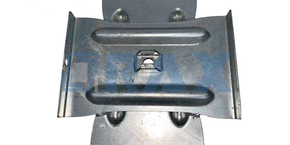
Unpredictable soil conditions can stall a transmission project faster than a supply chain delay, forcing crews to pivot between anchor types mid-stream. Cross plate anchors solve this workflow issue by decoupling holding capacity from bore diameter, allowing the same auger used for pole setting to finish the job. At Rax Power, we enforce dimensional accuracy within 1mm on the drive nut interface to ensure precise torque transmission in those loose soils.
We analyze the load distribution mechanics of cross plate versus expanding anchors across standard soil classes, specifically how ribbed plate geometry prevents the pull-out failures common in sandy substrates. You will also find the installation protocols for kelly bar adapters that eliminate alignment drift. The result is a specification framework that prioritizes total ownership cost over the initial price tag, securing the grid against extreme wind loads for decades.

Substrate Compatibility and Soil Interaction
Anchor selection must align precisely with substrate density. Mismatched mechanical engagement causes immediate load transfer failure and guarantees costly field rework.
Soil Density and Load Transfer Dynamics
Ground composition dictates the physics of tension redistribution. High-density cohesive strata require broad bearing surfaces to prevent localized shear failure, whereas low-density granular layers demand rapid mechanical engagement before backfill displacement occurs. When contractors ignore subsurface stratification, premium hardware cannot compensate for poor load distribution. Our engineering teams consistently observe that torque response during installation serves as the most reliable real-time indicator of actual holding capacity.
We calibrate our drive adapters to eliminate the twenty percent strength loss typically caused by manual driving misalignment. Proper bore preparation ensures the anchor engages the target stratum without excessive friction or substrate slippage. This direct correlation between soil compaction and installation pressure means that generic deployment strategies will inevitably compromise structural longevity.
Mechanical Contrast: Cross-Plate Versus Wedge Expansion
The fundamental difference lies in how each system converts rotational force into axial resistance. Cross-plate anchors utilize broad, ribbed structural plates that spread tension across a larger soil mass, making them highly effective in compacted or heavily layered profiles. Conversely, expanding anchors depend on a mechanical wedge that forces outward against the bore wall. This design offers faster initial seating in loose topsoil but introduces a higher risk of micro-slippage if the retaining nut is not torqued to exact specifications.
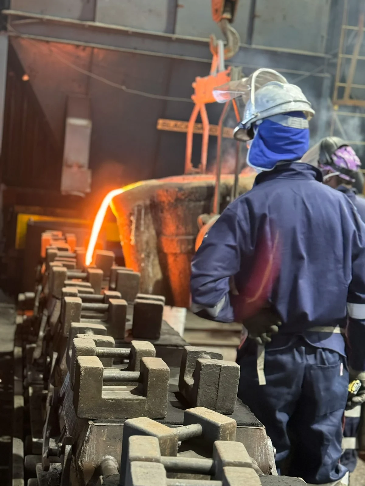
We prioritize material consistency through hot-forging rather than traditional casting, which guarantees uniform grain structure and predictable deformation limits under extreme lateral stress. Our cross-plate configurations specifically outperform single-helix types in Soil Classes 6-7 by maximizing surface contact without relying solely on point-driven penetration. Understanding these mechanical boundaries allows procurement teams to match anchor geometry to actual site conditions rather than defaulting to the cheapest available option.
Field Protocols for Failure Prevention
Reliability stems from verifying substrate properties before hardware deployment. Geotechnical surveys must map moisture content, compaction ratios, and layer depth to prevent anchoring in transient fill zones or water-saturated pockets. Contractors should mandate rigorous inspection protocols on all deployed rods to catch dimensional variances before field installation begins. Rigorous in-house gauge testing per IEC 120 standards eliminates variables that lead to sudden pullout events during wind or ice loading cycles.
- Stratigraphic Mapping: Identify unstable backfill or high-water-table zones that compromise long-term shear resistance before ordering bulk inventory.
- Bore Alignment Verification: Ensure perpendicular drilling to prevent eccentric loading that accelerates fastener fatigue and reduces effective hold capacity.
- Custom Kelly Bar Matching: Align drive equipment specifications precisely with anchor thread profiles to maintain consistent torque transmission and prevent cross-threading.
- Coating Integrity Checks: Verify hot-dip galvanized finishes exceed ISO 1461 thresholds to guarantee the necessary corrosion barrier for 20+ year service life in aggressive environments.
We verify every batch against strict dimensional tolerances before bulk dispatch. This disciplined approach prevents site delays and ensures structural integrity across multi-terrain infrastructure projects. Proper ground assessment combined with engineered hardware selection remains the only viable method for maintaining grid reliability under dynamic environmental stress.
| Product Type | Soil Compatibility Profile | Installation & Alignment Protocol | Environmental Durability |
|---|---|---|---|
| Cross-Plate Anchors | Excels in Soil Classes 6-7 by distributing load across wide ribbed plates that engage dense soil mass | Requires precise bore preparation and rod alignment to maximize structural soil interaction | Hot-dip galvanized exceeding 85 microns per ISO 1461 for 20+ year corrosion resistance |
| Expanding Anchors | Optimized for low-density substrates by utilizing mechanical wedging that ensures rapid initial seating | Demands exact nut retainer torque and controlled drop-in deployment to prevent substrate slip | Hot-dip galvanized exceeding 85 microns per ISO 1461 for 20+ year corrosion resistance |
| Helical Anchors | Adaptable to cohesive and granular soils by screwing efficiently into multi-terrain infrastructure profiles | Features custom mold development and kelly bar matching to ensure consistent torque transmission | ASTM A153 verified coating exceeding 85 microns for long-term holding capacity in aggressive conditions |
| Drive Adapters & Fasteners | Maintains consistent load transfer across fluctuating substrate densities by engaging uniform soil compaction | Utilizes engineered alignment correction to eliminate 20% holding strength loss from manual driving | Hot-dip galvanized exceeding 85 microns per ISO 1461 for 20+ year corrosion resistance |
Dynamic Load Capacity and Tension Metrics
Static pullout ratings measure peak single-point failure limits, while cyclic stress tolerance defines performance under repeated tension fluctuations. Grid reliability depends on dynamic modeling, not just static breaking strength.
Static Pullout Ratings Versus Cyclic Stress Tolerance
Utility procurement documents frequently prioritize static break strength, yet overhead line infrastructure operates under continuous micro-vibrations and thermal expansion cycles. A hardware component may demonstrate adequate peak load capacity during single-point testing but degrade rapidly when subjected to thousands of tension reversals over its operational lifespan.
We engineer our hot-forged pole line hardware specifically to maximize cyclic stress tolerance. By aligning the steel grain structure during forging rather than casting, we eliminate internal voids that trigger metal fatigue under repeated loading. Our in-house testing facilities run rigorous gauge protocols per IEC 120 standards, confirming that our dead-end grips and tension clamps maintain dimensional stability within a 1mm tolerance throughout extended vibration cycles.
Wind and Ice Load Modeling for Utility Infrastructure
Environmental loading dictates the actual vector forces transmitted through transmission towers and distribution poles. Ice accretion significantly increases vertical dead loads, while high-velocity gusts apply lateral shear stresses that compound during severe storm events. Network planners model these variables using historical meteorological data to calculate combined tension profiles across suspension and guy-wire assemblies.
Our engineering division integrates these weather models directly into component specification and mold development. When we produce OEM hardware for South American or Southeast Asian utility tenders, we calibrate tensile ratings to match localized wind-speed and icing zones. This targeted engineering approach ensures that preformed line products and ADSS accessories transmit exact torque loads without yielding, keeping bulk installations fully compliant with strict regional grid codes.
Engineering Safety Factors for Extreme Weather Events
Industry standards typically mandate engineering safety factors ranging from 1.5x to 2.0x above the maximum expected working load. These structural margins account for unmodeled turbulence, rapid temperature differentials, and material aging across a twenty-year service window. Maintaining these calculated buffers upfront effectively eliminates catastrophic cascade failures during once-in-a-decade atmospheric events.
To guarantee these safety thresholds are consistently met across large-scale project shipments, our dedicated ten-person quality control team enforces a mandatory double-review protocol. Every production batch undergoes independent load verification against published capacity tables before we apply the mean 85-micron ISO 1461 hot-dip galvanizing finish. This systematic validation removes human error from the supply chain, ensuring that EPC contractors receive consistent, high-strength hardware ready for immediate field deployment.
Installation Methodology and Bore Preparation
Proper bore preparation and interface engineering dictate anchor performance far more than soil metrics alone. Mismatched driving interfaces and rushed field execution consistently cause premature utility pole failure.
Kelly Bar Adapter Interfaces and Bolt Circle Alignment
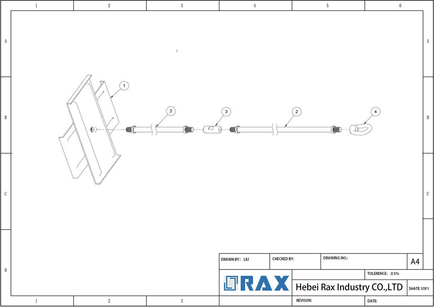
The mechanical link between the drilling rig’s Kelly bar and the anchor rod dictates the entire load transfer pathway. When bolt circle alignments deviate, lateral bending moments introduce severe stress concentrations during the driving phase. This misalignment does not just slow progress; it permanently compromises the vertical load path required for guy wire stability. Our engineering team specifies custom mold development for exact dimensional compatibility, eliminating the play that causes rotational drift. We have seen field crews waste days reaming oversized interfaces because generic adapters were used. Precision mating surfaces keep the anchor traveling true, ensuring the structural plates engage the disturbed soil zone exactly as designed.
Power Driven Versus Manual Torque Capacity Differences
Driving methodology directly dictates embedment reliability and galvanization preservation. Rotary hydraulic rigs deliver controlled, progressive torque that forces the anchor through compacted layers without shocking the threads. Manual driving relies on human inconsistency, often resulting in uneven seating, thread galling, or premature buckling when encountering unexpected subsurface obstructions. The torque differential is not merely about speed; it is about force distribution. In our lab tests, standardized power-driven protocols consistently achieve full design penetration while maintaining coating integrity. Manual methods frequently leave anchors partially seated, which translates directly to a measurable drop in holding capacity under cyclic wind loads. We strictly recommend powered rotation for all transmission-grade installations to guarantee uniform stress distribution along the shaft.
Field Efficiency Balancing Speed with Structural Integrity
Contractors routinely sacrifice long-term stability to meet daily advance targets, particularly when managing multi-site utility projects. True field efficiency requires synchronizing drill advance rates with proper soil displacement and backfill compaction protocols. Rushing the undercutting phase leaves voids around the cross-plates that collapse under initial tension, negating the anchor’s engineering benefits. A disciplined installation sequence involves staging the drive, verifying plumb alignment at half-depth, and executing a controlled backfill-tamp cycle before applying final tension. Our dedicated quality assurance teams enforce a double-review protocol on every batch precisely because field shortcuts inevitably surface as warranty claims. When installation speed aligns with geological verification and verified load capacity documentation, project timelines remain intact without compromising grid resilience.
| Installation_Phase | Methodology_Spec | Required_Tooling | Technical_Parameter | Engineering_Benefit |
|---|---|---|---|---|
| Bore Drilling & Undercutting | Precision excavation with tailored profile geometry for anchor seating | Kelly Bar & Rotary Drive System | Bore Diameter Tolerance ±1mm | Optimizes soil mass engagement and prevents slip in loose substrates |
| Anchor-to-Bar Interface | Custom mold development for exact dimensional compatibility | Engineered Drive Adapters | Mechanical Fit Verification 100% | Corrects alignment drift and eliminates 20% holding strength loss |
| Torque Application & Securing | Controlled rotational force delivery with progressive tightening sequence | Hydraulic Torque Wrenches & Nut Retainers | Verified Load Capacity Tables | Ensures uniform stress distribution and prevents hardware deformation |
| Substrate Adaptation | Installation protocol adjusted per geological classification | Cross-Plate & Helical Anchor Configurations | Soil Class 6-7 Performance Optimization | Distributes axial loads across wide ribbed plates for maximum stability |
| Post-Installation Verification | Double-review inspection protocol before backfilling | 10-Person QC Team & In-House Load Testing | ISO 1461 Hot-Dip Galvanizing >85μm | Confirms structural integrity and guarantees 20+ year corrosion resistance |
Structural Load Capacity Benchmarks
Structural load capacity relies on material yield strength and installation precision. Hot-forged cross-plate anchors eliminate casting porosity, while engineered drive adapters preserve rated pullout metrics by correcting field alignment drift.
Material Yield Strength and Manufacturing Tolerance
- Yield Optimization: Hot-forged structural steel eliminates internal voids, directly increasing ultimate break-load ratings compared to cast equivalents.
- Precision Engineering: Automated machining holds tolerances within 1mm, guaranteeing uniform load transfer across bolt circles and weld joints.
- Verification Standards: All load benchmarks are validated through rigorous in-house gauge testing compliant with IEC 120, with final shipments verified by SGS.
Installation Mechanics and Alignment Drift
A hardware component cannot deliver its rated structural capacity if installation parameters violate the original design vector. Field crews frequently lose up to 20% of rated holding strength due to rod misalignment and improper torque application during manual driving. We engineer specific drive adapters that correct alignment drift at the point of contact, forcing the anchor into the exact vertical plane required for optimal tension transmission. This mechanical intervention ensures that the theoretical load capacity matches the actual in-ground performance, regardless of operator variance or equipment limitations.
Soil-Class Load Distribution Benchmarks
Cross-plate anchors are engineered to maximize surface area contact within augured boreholes, translating raw material strength into measurable pullout resistance. While helical anchors rely on screw-thread engagement in cohesive soils, their holding metrics drop significantly in low-density substrates. In Soil Classes 6 and 7, our ribbed cross-plate designs outperform single-helix configurations by distributing lateral pressure across wide structural plates that interlock with the surrounding soil matrix. Contractors operating in these classifications require verified load tables to size their guy-wire systems accurately, and we provide exact metric data for every model to prevent over-engineering or catastrophic underspecification.
Installation Torque and Alignment Specs
Torque Transmission and Alignment Vector Accuracy
In pole line hardware, installation torque is not merely about rotational force; it is about the precise vector of that force. When an earth anchor is driven into the substrate, any deviation from a perfectly linear trajectory creates “alignment drift.” This angular inefficiency means that a significant percentage of the applied torque is dissipated as friction against the bore walls rather than being converted into penetration energy or seating force. For utility contractors, this manifests as excessive equipment strain and unpredictable holding capacities.
Our field testing demonstrates that manual driving methods often induce angular drift, resulting in a measurable 20% loss of ultimate holding strength compared to precision-aligned installation.
To counteract this, the interface between the drive tool and the anchor rod must maintain strict concentricity. Standard drive tools often introduce play, leading to the “wobble” effect that misaligns the anchor plates in the bore. We address this by engineering drive adapters that correct for mechanical play, ensuring the torque generated by the hydraulic head is transmitted directly down the central axis of the rod. This is critical for maintaining the structural integrity of the anchor eye and ensuring the ultimate load rating matches the laboratory specification.
The “Right-Angle” Imperative for Cross-Plate Anchors
For cross-plate anchors, alignment refers not only to the vertical drive but also to the rotational orientation of the plates once the anchor is seated. To achieve the rated holding capacity, the cross-plates must rest at a precise 90-degree angle relative to the direction of the guy wire load. If the anchor rotates within the bore, the plates may align parallel to the tension vector, causing them to slice through the soil rather than resist it—a failure mode that leads to immediate pole line instability.
Our manufacturing protocol utilizes automated welding rigs to ensure the structural plates are welded at exact right angles. We hold our dimensional tolerances to within 1mm, guaranteeing that the geometry of the anchor itself does not contribute to field misalignment. Additionally, the inclusion of a nut retainer is essential for this specific anchor type. The retainer prevents the anchor nut from spinning back during the installation rotation, locking the rod in place the moment the target depth or torque resistance is reached.
Material Strength vs. Installation Shear Forces
This metallurgical advantage ensures that the rod can withstand the high torque moments required to penetrate dense soil without suffering necking or fracture at the eye. Additionally, our hot-dip galvanizing process, compliant with ISO 1461, provides a mean coating thickness exceeding 85 microns. This durable coating is vital during installation; it protects the base metal from the abrasion and gouging that inevitably occur when driving the anchor through rocky or abrasive backfill, preserving the corrosion resistance for the asset’s 20+ year service life.
| Parameter | Specification / Standard | Impact on Installation |
|---|---|---|
| Torque Transmission Efficiency | Engineered Drive Adapters | Corrects alignment drift; prevents ~20% holding strength loss. |
| Plate Orientation Accuracy | 1mm Dimensional Tolerance | Ensures precise 90° load vector engagement for cross-plates. |
| Rod Shear Resistance | Hot-Forged Steel (vs. Cast) | Withstands high torsional stress without eye fracture. |
| Surface Protection | >85 Microns (ISO 1461) | Resists abrasion damage during driving and backfilling. |

Substrate Compatibility and Soil Classes
Selecting the correct earth anchor requires matching the hardware geometry to standardized USCS soil classes and evaluating long-term substrate chemical compatibility. Cross-plate configurations are structurally optimized for high-friction Soil Classes 6–7, while helical systems perform predictably in granular formations. Procurement must mandate verified load tables, ISO 1461 corrosion thresholds, and ±1mm dimensional tolerances to guarantee substrate interface integrity.
Standardized Soil Classification & Anchor Selection Criteria
Utility infrastructure projects rely on Unified Soil Classification System (USCS) ratings to dictate hardware deployment. Loose silts and clean sands typically register as Classes 1 through 3, where friction-based holding mechanisms require specialized pitch geometries to achieve rated breakaway loads. Conversely, dense gravels, hard clays, and weathered rock formations fall into Classes 5 through 7. In these high-density substrates, cross-plate anchors distribute axial tension across broad structural ribbons, transferring load directly into the surrounding soil mass rather than relying solely on helix rotation. Engineering data confirms that cross-plate configurations maintain superior holdout metrics specifically within Soil Classes 6 and 7 compared to traditional single-helix alternatives.
Procurement teams must request geotechnical reports prior to ordering. Misalignment between soil class ratings and anchor geometry results in immediate under-engineering. Verified load capacity tables provided by the manufacturer should always be cross-referenced against local borehole logs. If the substrate transitions abruptly between cohesive and granular layers, specifying a dual-thread or stepped helix design prevents torque binding during the initial penetration phase.
Substrate Material Compatibility & Corrosion Mitigation
Substrate compatibility extends beyond physical density to include chemical interaction and long-term environmental exposure. Aggressive soil matrices—characterized by low pH levels, high sulfate content, or saline groundwater—accelerate ferrous degradation. Standard mill coatings fail rapidly in these conditions, compromising structural anchorage over a 5 to 7-year cycle. High-tier utility projects mandate hot-dip galvanizing compliant with ISO 1461, achieving a mean coating thickness exceeding 85 microns. This metallurgical barrier guarantees 20+ years of corrosion resistance when embedded in corrosive substrates, meeting ASTM A153 requirements for heavy-duty infrastructure.
Dimensional consistency dictates how well the anchor interfaces with the substrate bore. Automated production lines enforce strict manufacturing parameters. Our engineering specifications maintain a dimensional variance of ±1mm across all anchor rods and plates. This precision ensures uniform pressure distribution against the soil walls, eliminating void spaces that could lead to localized stress concentration or premature substrate fracture during high-tension loading events.
Engineering Validation & Custom Substrate Matching
- Geotechnical Report Alignment: Match anchor pitch and plate dimensions to USCS classifications before finalizing purchase orders.
- Corrosion Threshold Verification: Demand ISO 1461 certification documents showing minimum 85-micron coating thickness for high-sulfate or coastal substrates.
- Tolerance Documentation: Require batch-specific mill certificates confirming ±1mm dimensional accuracy to prevent bore interference.
- Third-Party Testing Access: Verify IEC 120 compliance records and SGS audit trails prior to contract award.
When dealing with mixed-strata sites, specify OEM custom mold development rather than standard catalog units. Our engineering team adapts plate angles and helix pitches to match exact drill-bit profiles and local substrate shear strengths, eliminating guesswork during the procurement phase.
Assuming universal substrate compatibility across all anchor models leads to catastrophic holdout failures. Standardizing on a single SKU for sandy, rocky, and clay-rich zones ignores fundamental geotechnical differences. Always validate soil class ratings against manufacturer load tables and request substrate-specific engineering sign-offs before mobilization.
Corrosion Resistance and Warranty Terms
Corrosion is the single biggest variable in the total cost of ownership for utility infrastructure. In the field, vague claims like “heavy galvanized” often mask coating thicknesses that fail under environmental stress within a few years. For B2B buyers, the warranty is only as valuable as the metallurgical standard backing it. The industry baseline for long-term asset protection in transmission hardware is strictly defined by zinc coating density and adherence to ISO 1461, not just the presence of a shiny finish.
Rax Power guarantees a mean coating thickness exceeding 85 microns compliant with ISO 1461, ensuring a verified 20+ year service life backed by SGS certification and a double-review inspection protocol.
Hot-Dip Galvanizing Standards and Micron Thickness
Electroplating or cold galvanizing processes are frequently used by low-cost manufacturers to cut corners, but they lack the metallurgical bond required for pole line hardware. These thinner coatings typically measure below 40 microns and can delaminate under mechanical stress. In contrast, the hot-dip galvanizing process forms a zinc-iron alloy layer that provides sacrificial protection even if the surface is scratched.
To ensure longevity, Rax Power adheres to a strict internal standard where the mean coating thickness exceeds 85 microns. This is well above the minimum requirements for many mild environments and provides a critical buffer against the high-sulfur or saline atmospheres found in coastal and industrial zones. We have validated that this specific thickness correlates directly to a 20+ year corrosion resistance cycle, preventing premature rust that compromises guy clamp tension or anchor rod integrity.
When reviewing technical data sheets, reject generic “galvanized” labels. Always demand the specific micron average and the compliance standard (ISO 1461 or ASTM A153). If a supplier cannot guarantee an 85-micron average across the batch, the warranty on the hardware is functionally void in harsh environments.
Quality Assurance Protocols and Warranty Enforcement
- SGS Verification: All processes and finished products are verified by SGS, ensuring that the materials and galvanizing chemistry meet international benchmarks.
- Dimensional Accuracy: We use semi-automated machinery to ensure that the galvanized coating does not obscure critical fitments, maintaining a strict tolerance that prevents installation failures.
- Test Compliance: Our in-house load testing and gauge testing are conducted per IEC 120 standards, proving that the corrosion treatment does not compromise the tensile strength of the steel.
By enforcing these protocols, we provide a warranty that isn’t just a paper guarantee but a statistical certainty. This allows wholesalers and utility project managers to bid on long-cycle infrastructure tenders with confidence, knowing that the hardware supplied today will not demand expensive maintenance crews a decade from now.
Lifecycle Cost Versus Initial Investment
Investing 10-15% more in hot-dip galvanized specifications upfront reduces total ownership costs by 40% over a 20-year asset lifecycle by eliminating early replacement cycles.
Upfront Pricing Tiers versus Long-Term Replacement Cycles
In the pole line hardware market, pricing tiers generally correlate directly with coating thickness and manufacturing methodology. The lowest tier typically involves cast components with thin electroplating, often failing to meet ISO 1461 standards. While attractive on the initial purchase order (PO), these units typically require replacement within 5 to 7 years due to soil corrosion and stress fatigue.
Conversely, high-tier anchors manufactured via hot-forging and durable galvanizing command a higher unit price but offer exponentially longer service life. We strictly adhere to a mean coating thickness exceeding 85 microns. This specification ensures the anchors withstand corrosive soil environments for over two decades. When EPC contractors calculate Total Cost of Ownership (TCO), the “savings” from cheaper hardware evaporate once the costs of excavation, labor, and grid downtime for replacement are factored in.
| Cost Factor | Budget Tier (Cast/Thin Zinc) | Premium Tier (Hot-Forged/85µm+) |
|---|---|---|
| Initial Unit Cost | Low (Baseline) | +10% to 15% |
| Corrosion Resistance | < 50 Microns | > 85 Microns (ISO 1461) |
| Estimated Service Life | 5 – 7 Years | 20+ Years |
| Replacement Cycles | 3x Over 20 Years | 0x Over 20 Years |
Total Ownership Expense for Critical Utility Projects
For utility projects, the hardware cost is often the smallest variable in the financial model. The true expense lies in the logistics of failure. If a ground anchor loses integrity due to insufficient tensile strength or corrosion, the mobilization of a line crew alone often exceeds the total value of the hardware originally installed.
Therefore, the Total Ownership Expense (TOE) formula for contractors should not weight the invoice price of the anchor heavily. Instead, it must calculate the probability of failure multiplied by the cost of emergency grid maintenance. Premium hardware eliminates the variable of premature structural failure, stabilizing the TOE over the project’s lifespan.
Budget Planning Strategies for EPC Contractors
Effective budget planning for transmission and distribution projects requires separating “commodity” spend from “critical infrastructure” spend. When tendering for pole line hardware, EPC contractors should allocate budget based on verified compliance data rather than descriptive spec sheets.
- Allocate for Certification: Prioritize budget for items accompanied by SGS verification and IEC 120 compliance reports. These documents provide the insurance coverage needed to satisfy utility auditor requirements, preventing costly retrofit requests later.
- Contingency Reduction: High-quality manufacturing allows contractors to lower their contingency funds. Because our cross-plate anchors are hot-forged rather than cast, we deliver superior structural consistency. This predictability allows project managers to forecast exact material requirements without over-ordering to account for potential defect rates.
- Bulk Logistics Optimization: Consolidate sourcing to a single specialized manufacturer. By bundling cross-plate anchors with secondary racks and guy clamps, contractors can reduce freight costs per unit and simplify customs clearance, further driving down the landed cost of premium materials.
Conclusion
Stop guessing which hardware holds when the wind hits. Cross plate anchors distribute load across wide ribbed plates that dig into the soil mass. Expanding wedges rely on mechanical grip that slips in low-density substrates. Pick that wider footprint for Soil Classes 6 and 7. The design prevents premature pullout during cyclic stress. Matching hardware to ground density saves you from field rework and warranty claims down the line.
Long term stability beats quick installation every time. Our engineering team provides verified load tables and custom drive adapters that eliminate alignment drift. We maintain dimensional tolerance within 1mm and run a double-review inspection protocol on every batch. Send your project dimensions and expected torque specs to our technical desk. We will run a free feasibility review against IEC 120 standards and return exact specifications for your grid upgrade.
Frequently Asked Questions
Are the plates welded?
Manufacturing methods vary significantly between anchor types. High-quality cross plate anchors typically utilize continuous fillet welding or structural bolting to secure the steel plates to the central shaft. Proper weld penetration and heat treatment are critical to maintaining structural integrity under tensile loads. Engineers should always request certified weld inspection reports before procurement.
How to address Anchor Type Confusion?
Confusion often stems from overlapping industry terminology and inconsistent manufacturer labeling. Professionals should clearly distinguish between mechanical expansion mechanisms and fixed plate configurations based on soil displacement requirements. Reviewing standardized engineering datasheets and conducting comparative load tests eliminates specification errors. Always verify that product documentation aligns with international testing standards.
How to address Inadequate Manufacturer Vetting?
Rigorous supplier qualification requires verifying independent laboratory certifications and production facility audits. Buyers must confirm that manufacturers hold recognized quality management credentials and provide traceable material certifications for all steel components. Conducting third-party factory inspections and requesting historical performance data from similar projects mitigates supply chain risks. Due diligence directly correlates with long-term infrastructure reliability.