
An alley arm carries its load from one side only. There is no twin arm on the far side of the pole to share the weight of conductors, ice, and wind. Every pound acting at the arm tip must return into the pole through one steel member. That member is the alley arm brace, and alley arm brace design is a compact lesson in structural mechanics. Each feature it carries solves a specific force problem.
The reasoning below comes from that side of the business. RaxPower has manufactured pole line hardware since 2003, and 170+ specialists on its engineering and production teams supply these braces to utilities and distributors worldwide. What follows explains why each design choice on the bar earns its place, from the 45-degree setting down to the coating.
Why a Side-Mounted Arm Needs a Brace
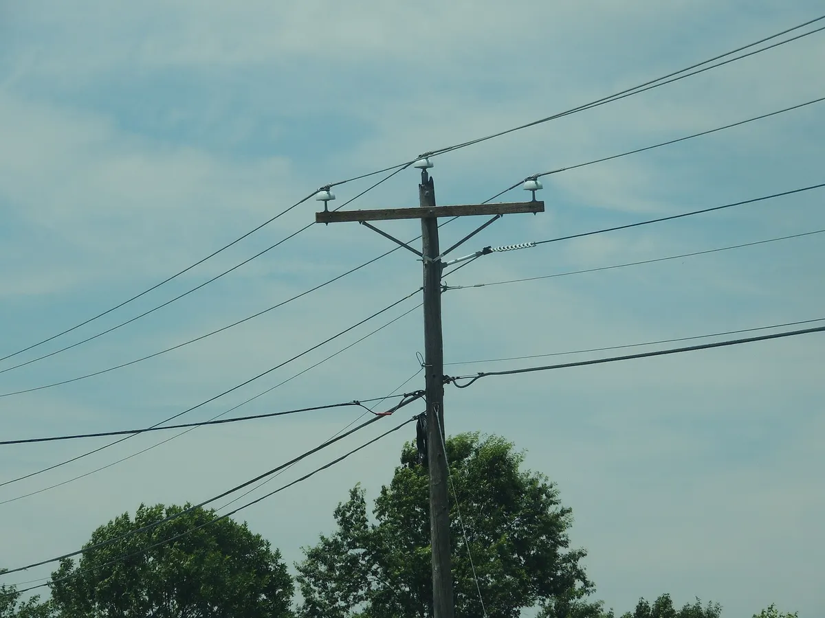
An alley arm is simply a crossarm mounted to one side of the pole, a fixture in the broader family of pole line hardware. MacLean Power Systems describes the category plainly: alley arms need rigid bracing to keep distribution and transmission lines in proper alignment. The reason is basic statics. A bar bolted flat against a pole face resists shear, but it cannot by itself stop the arm from rotating.
Weight at the arm tip creates a twisting moment around the pole. Wind adds a sideways component, and line tension adds a third. Until the arm is tied back to the pole below, that moment has nowhere to go.
The brace supplies the missing leg. It runs from the underside of the arm down to the pole at an angle, so the three members form a closed frame. What happens next is pure geometry.
The Triangle: Geometry That Cannot Fold
A triangle is the only plane frame whose shape is fixed by the lengths of its sides. Three members pinned at three corners have exactly one possible shape. A four-sided frame has none: push its top edge and it racks sideways, as if the corners were hinges.
That fixed shape is what engineers mean by rigidity in alley arm brace design. Because the arm, the pole, and the brace form a triangle, no load can deform the assembly without stretching, squeezing, or shearing one of the members. The brace is the member added purely to close that triangle.
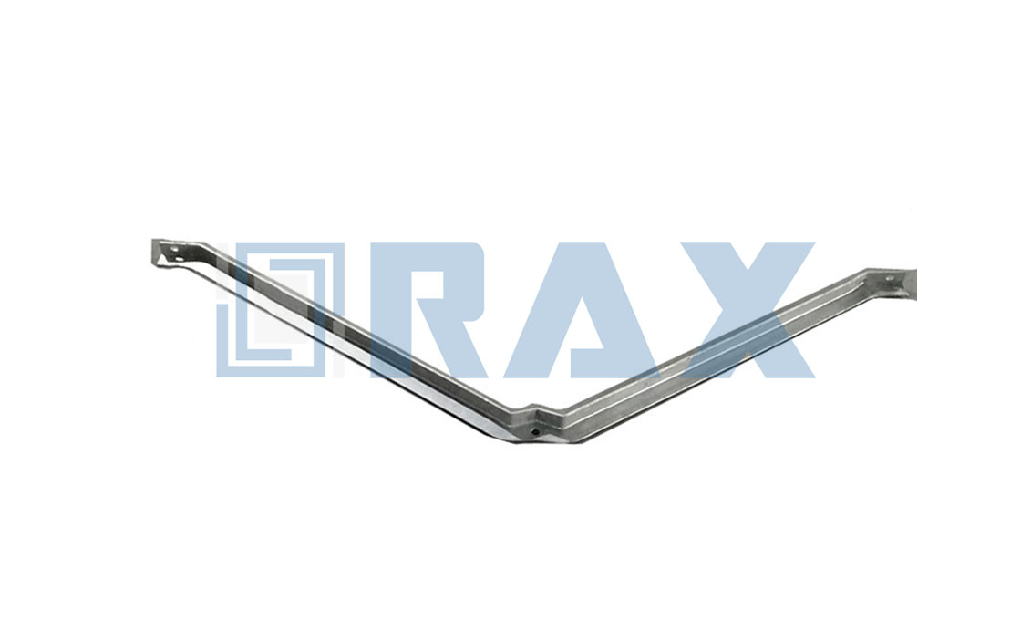
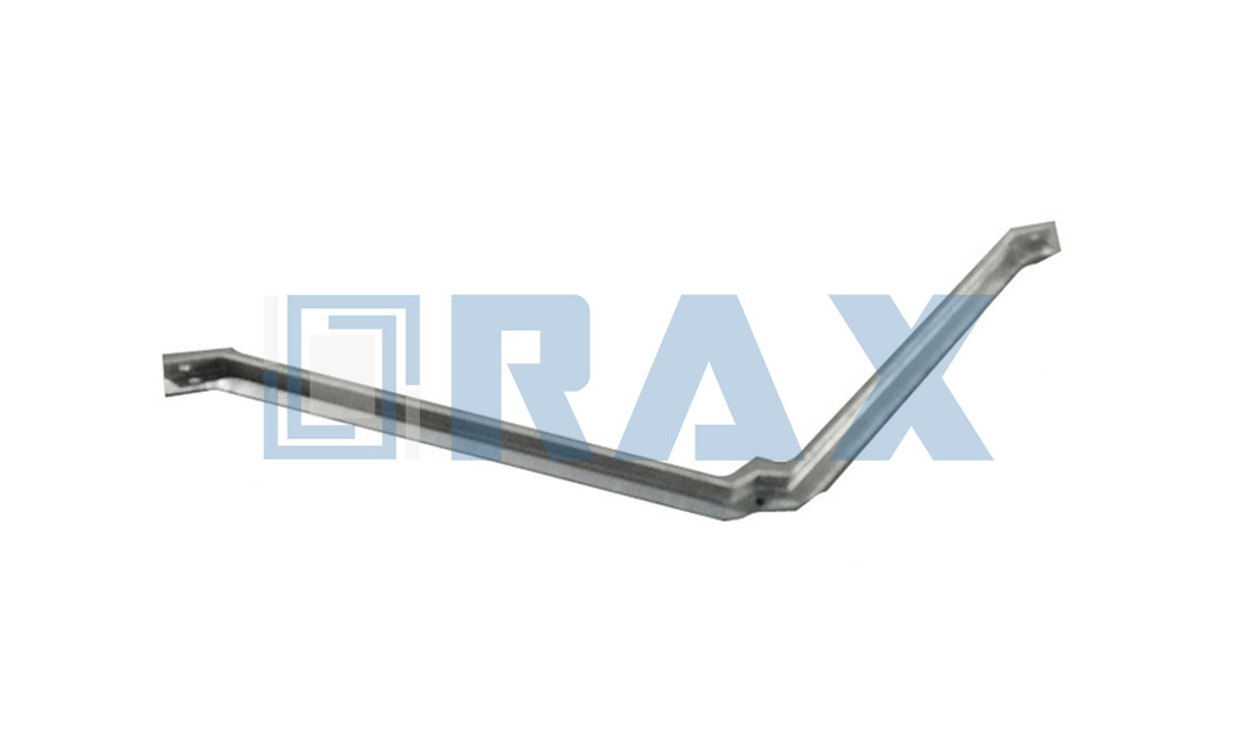
Real braces are not straight bars. Each one carries a crank near mid-span that bends the profile into a shallow V. The crank lets both ends sit flat against their mounting faces while the middle stands off from the pole. That is what allows a single bar to bridge two surfaces meeting at an angle.
How Load Travels From Arm Tip to Pole
Picture the arm tip loaded with ice-covered conductor. That force travels along the arm toward the pole, and the brace intercepts it partway. The load then moves down the brace as a push along its length and arrives at the pole below the arm, where the pole carries it to ground.
Under ordinary vertical load the brace works as a compression member, which means it is being squeezed. If uplift or wind reversal lifts the arm, the same bar switches to tension and pulls against its connections. This dual role is why both ends use engineered fasteners: a machine bolt at the arm and two 1/2-inch lag screws at the pole.
Members that only push or pull are efficient. They carry load as pure axial force with almost no bending, which is the payoff of the triangle. That efficiency lets a light steel bar do work that would otherwise demand a much heavier arm.
Why Forty-Five Degrees Became the Standard Angle
Ask three suppliers and you will hear one number. MacLean Power Systems publishes 45-degree mounting for its alley arm braces, and RaxPower specifies the same angle for every length in its range. The consistency is not fashion; it falls out of the trigonometry.
A force traveling along a 45-degree brace arrives with equal horizontal and vertical components, because the sine and cosine of 45 degrees are identical. Neither end connection is asked to resist more of the load than the other. The angle also keeps the bar compact against the pole, which matters in the alleys that give side-arm construction its name.
Change the angle and you change three things at once: the force in the bar, the length of the bar, and the space it occupies beside the pole. Forty-five degrees keeps all three within practical limits. That balance is why 45 degrees hardened into the default for alley arm brace design.
What the Angle-Steel Section Actually Does
Section choice is the second half of alley arm brace design. Catalog braces are rolled from equal-leg angle steel, typically 1-3/4 by 1-3/4 inches with a 3/16-inch wall. RaxPower lists that section on its 5-foot and 7-foot alley arms and steps up to 2 by 2 by 1/4-inch steel on the 10-foot length.
An L-shaped section puts material in two perpendicular directions at once. The vertical leg resists the bending that comes with compression loading, while the horizontal leg presents a flat face for the mounting holes and the welded step. Compared with a flat bar of similar weight, the angle resists buckling in two directions instead of one.
Length drives the step up in section. A longer bar has more unbraced length to buckle, so the 10-foot brace gets thicker legs and a heavier wall. The table below shows how the numbers line up in one current catalog.
| Brace length | Mounting hole | Angle size | Pieces per carton | Carton weight | Listed capacity per wire |
|---|---|---|---|---|---|
| 5 ft | 9/16 in | 1-3/4 x 1-3/4 x 3/16 in | 1 | 13 lbs | 32,000 lbs |
| 7 ft | 11/16 in | 1-3/4 x 1-3/4 x 3/16 in | 5 | 86 lbs | 32,000 lbs |
| 10 ft | 11/16 in | 2 x 2 x 1/4 in | 5 | 181 lbs | 32,000 lbs |
Figures above come from the RaxPower alley arm listing for its alley arm models. Capacities are listed values, not field guarantees, and every manufacturer publishes its own table. The pattern behind the columns, though, is the same across the industry.
Hole Sizes Follow the Hardware, Not Guesswork
Those holes are sized with a quiet rule: drill clearance about 1/16 inch larger than the fastener. MacLean states it openly in its flat brace catalog, listing 7/16-inch holes for 3/8-inch bolts and 9/16-inch holes for 1/2-inch lag screws or through bolts. Add the same 1/16 inch to a 5/8-inch fastener, and you arrive at the 11/16-inch holes fitted to longer alley arm braces.
The clearance is not slack. It absorbs the tolerance reality of fieldwork, because drilled pole holes and punched bracket holes never line up perfectly. The larger 11/16-inch opening exists partly to forgive boring inaccuracy at the pole end, where a machine bolt or lag screw must pass through wood that moves with weather.
Undersized holes stop an assembly halfway through installation. Oversized holes let the connection work loose under vibration and concentrate stress on thread roots. The catalog sizes sit deliberately between those two failure modes, which is why 9/16 and 11/16 recur across suppliers.
One Welded Bend That Doubles as a Step
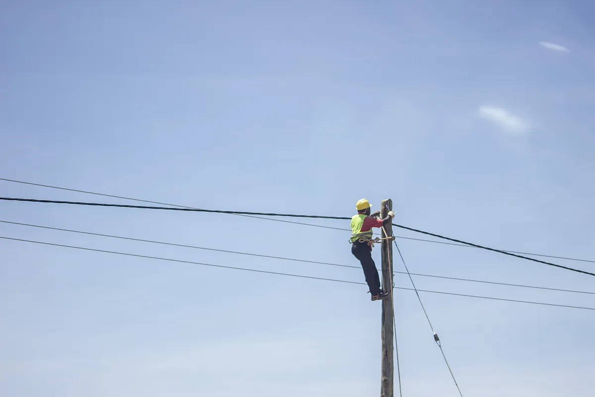
Look at a finished brace and you will find a small tab welded near the crank. Suppliers describe it as a solidly welded lineman step, and its first job is exactly what the name says: a foothold. The product notes credit the step with preventing slipping during installation.
The second job is structural economy. The brace already occupies the spot where a climber working a side arm needs support. The step therefore adds function without a separate pole step and another set of holes. Welding it in place rather than bolting it removes loose parts that could back off under vibration, and it keeps the coating line uninterrupted across one continuous steel assembly.
Galvanizing Is Part of the Design
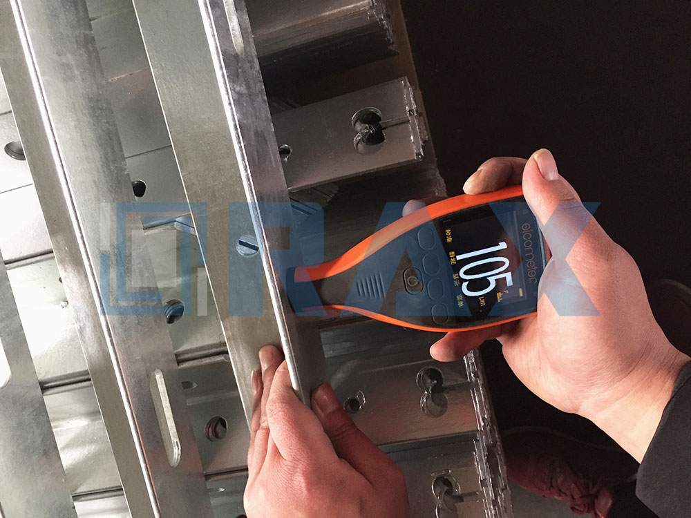
A brace lives outdoors for decades, so the coating is designed in rather than sprayed on. Catalog alley arms are hot-dip galvanized steel, and the product sheet specifies ASTM A123 and ISO 1461 with a mean coating above 85 microns on its alley arms. Those two standards govern how thick the zinc must be and how the bath process is controlled.
Hot-dip galvanizing suits this particular geometry. Molten zinc coats every surface, including the inside faces of the angle and the walls of drilled holes. The deposit is at least as thick on corners and edges as on flat surfaces, where paint behaves in the opposite way and thins exactly where steel is most exposed.
The open L-section helps the process too. Zinc has to reach every face and then drain back cleanly, and a single angle carries no enclosed pockets to trap air or metal. The same mounting holes that fasten the brace plausibly double as flow paths during dipping, and rounded brace ends likely shed coating more evenly than sharp corners. Those side benefits are design rationales rather than documented requirements.
What Good Design Prevents in the Field
Trace each choice to the failure it prevents. The triangle prevents rotation of a single-sided arm. The 45-degree setting prevents overloaded end connections, the angle section prevents buckling without padding the weight, and the 1/16-inch hole rule prevents both assembly fights and loose joints.
Alignment is the outcome utilities care about most. MacLean ties rigid bracing directly to proper alignment of distribution and transmission lines, because a sagging side arm shows up quickly as wrong conductor spacing and clearance losses. In our experience, the braces that hold alignment for decades are the ones whose details were never negotiable: straight bar stock, clean holes, full welds, and honest coating thickness.
That is the design principle in one sentence. The alley arm brace design turns a one-sided cantilever into a triangle, and every dimension on the bar serves that conversion. When the details are right, the hardware disappears into the landscape for decades, which is exactly what RaxPower engineers aim for when they cut, drill, weld, and galvanize each brace.
Key facts. An alley arm brace is an angle-steel member that supports a side-mounted crossarm at a 45-degree angle, completing a rigid triangle between the arm and the pole.
Standard sections are 1-3/4 x 1-3/4 x 3/16 inch for 5 ft and 7 ft braces, and 2 x 2 x 1/4 inch for the 10 ft brace. Mounting holes measure 9/16 inch or 11/16 inch, sized about 1/16 inch larger than the fastener.
Braces attach to the arm with a machine bolt and to the pole with two 1/2-inch lag screws, and they include a solidly welded lineman step.
RaxPower lists lengths of 60, 84, and 120 inches, with hot-dip galvanizing per ASTM A123 and ISO 1461 at a mean coating above 85 microns. Listed load capacity reaches 32,000 lbs per wire.
Frequently Asked Questions
Why is an alley arm brace set at 45 degrees?
At 45 degrees the brace’s horizontal and vertical force components are equal, so neither end connection carries more of the load than the other. The angle also keeps the bar compact against the pole, which suits the tight clearances that side-arm construction exists for.
What size steel is an alley arm brace made from?
Most catalog braces use 1-3/4 by 1-3/4 by 3/16 inch hot-dip galvanized angle steel. Longer braces step up: the catalog lists 2 by 2 by 1/4 inch steel on the 10-foot model, because a longer bar needs a stiffer section to resist buckling.
Why do braces have 9/16-inch or 11/16-inch holes?
Clearance holes run about 1/16 inch larger than the fastener. A 9/16-inch hole suits 1/2-inch bolts and lag screws, while 11/16-inch holes suit 5/8-inch-class pole hardware and forgive boring inaccuracy in the field.
What does the welded lineman step do?
It gives climbers a secure foothold at the height where the brace already crosses the pole, preventing slipping during installation. Because it is welded rather than bolted, it adds no loose parts and no extra holes in the steel.
How is an alley arm brace protected against corrosion?
Braces are hot-dip galvanized to ASTM A123 and ISO 1461; RaxPower specifies a mean coating above 85 microns. The zinc coats edges, corners, and hole walls fully, which matters on a drilled and welded angle section.