
No-wrench screw anchors eliminate the bottleneck of traditional installation by combining a drop-forged eye rod with a welded helix, allowing crews to drive them into the ground using simple turning bars or standard hole-boring machine adapters. This design choice directly addresses the friction in utility grid projects where labor costs and timeline delays are critical. Instead of waiting for specialized heavy equipment or dealing with complex torque calculations, installers can achieve rapid deployment with minimal overhead.
The holding capacity of these systems is heavily dependent on soil density and installation quality. A properly installed 1-1/4 inch anchor with a 14-inch helix can deliver up to 16,000 pounds of load capacity in medium dense soils, but that number drops significantly if the anchor deviates from the guy wire alignment by more than five degrees. We will break down how to calculate Safe Working Load based on actual soil classes and why torque requirements matter more than you think when installing in sandy conditions. This guide covers the mechanical principles behind the no-wrench system, detailing how to assess geotechnical conditions before driving, correct common alignment issues that compromise load integrity, and select the right helix size for your specific project. You will learn how to ensure long-term corrosion resistance through proper ASTM A123 compliance and avoid the premature failures that plague under-specified foundations.
Assessing Soil Conditions Before Installation
Soil Classification Standards for Anchor Selection
The mechanical performance of any helical earth anchor is entirely dependent on the geotechnical classification of the soil it is installed into. Field engineers must categorize the ground profile into specific load-bearing classes before selecting a shaft diameter or helix configuration. The standard industry protocol utilizes a Class 8 to Class 5 scale, where Class 8 represents extreme rocky conditions and Class 5 denotes soft clay. Our team’s 21 years of export experience across Russia and South America confirm that mismatching anchor steel grade to soil class is the primary cause of premature installation failure.
Evaluating Holding Capacity by Soil Type
Holding capacity is not a static number but a function of torque-to-capacity correlation. Engineers calculate safe working loads based on the final installation torque achieved in specific soil classes. We strictly adhere to in-house load testing per IEC 120 standards to validate these figures. Our engineering data indicates that while theoretical models vary, actual field performance is heavily influenced by the uniformity of the soil strata. For instance, a Class 5 sandy clay will show significant variance compared to the consistent bearing of Class 7 compact sand.
Torque-to-capacity correlations require precise material specifications to ensure structural reliability under extreme wind loads. To ensure accuracy, we utilize a conservative safety factor when translating torque readings into load capacity, aligning with ASTM A123 Class C galvanizing standards for corrosion protection. This approach prevents over-engineering in low-risk areas while guaranteeing that the helix plate’s 1/4″ (6.35mm) thickness performs as designed, whereas the rod itself meets dimensional tolerances of 1mm accuracy.
Pre-Installation Geotechnical Assessment Protocols
Before deploying No-Wrench Screw Anchors, a rigorous pre-installation assessment is mandatory to mitigate ground variability risks. This process involves analyzing historical geological surveys and, where necessary, conducting small-scale pilot installations. Our QC protocols require verifying that the extension rod couplings align precisely with the anticipated torque requirements for the specific soil class identified at the site.
Never assume uniform soil composition across a large utility grid. Variations between Class 6 and Class 7 soils can drastically alter torque requirements. Always verify local geotechnical reports against Rax Power’s soil-class mapping to select the correct helix pitch and shaft diameter.
How the No-Wrench System Works
The Engineered “No-Wrench” Drive Mechanism
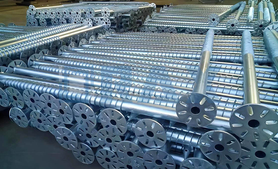
The core innovation of the no-wrench screw anchor lies in its integrated drive system, which completely removes the dependency on external Torque bars or wrenches during field installation. Unlike traditional anchors that require a separate clamping mechanism to transfer rotational force, this design features an integral forged eye rod welded directly to the helical plate assembly. This eliminates weak points associated with loose couplings and ensures that the torque applied by the installer is transferred instantaneously to the helix without mechanical slippage.
The ‘eye’ at the top of the rod is engineered with a precise geometry—often referred to as a thimble or triple-eye configuration—to accommodate a standard turning bar or power auger adapter. For manual installation, the large opening allows a worker to insert a straight steel bar through the eye and use their body weight to screw the anchor into the ground. This simple, direct-drive physical interface drastically reduces installation time per pole and removes the need for specialized heavy-duty wrenching equipment on-site.
Structural Integrity of the Welded Helix Connection
From a structural engineering perspective, the weld connecting the eye rod to the helix is the most critical load-bearing component. Because the no-wrench system relies entirely on turning the anchor by this central eye rod, all torsional stress is concentrated at the weld interface. To withstand the high-friction resistance of dense soil and clay, these anchors are manufactured using drop-forged steel rods, which provide superior grain structure and impact resistance compared to cast alternatives.
Material Specifications and Corrosion Protection
Surface treatment protocols must distinguish between small hardware and structural pole line hardware to guarantee long-term durability. Because the installation process involves significant physical handling and driving into abrasive soils, the surface treatment of the no-wrench anchor must be Sturdy. High-standard no-wrench screw anchors are constructed from hot-dip galvanized steel, strictly adhering to ASTM A123 Class C or ISO 1461 (>85 microns mean coating) standards. This coating provides a sacrificial layer of zinc that protects the forged steel from rust and corrosion across diverse environmental conditions, ensuring the anchor maintains its structural integrity throughout the lifespan of the utility pole.
Load Capacity Across Different Soils
The Impact of Soil Class on Ultimate Holding Strength
When deploying screw anchors for utility poles in high-stress environments, the single greatest variable affecting structural integrity is soil classification. Load capacity does not scale linearly; it is fundamentally dictated by the shearing strength of the surrounding earth. A helix embedded in Class 5 soft clay will exhibit drastically different pullout performance compared to one set into Class 8 rock, even if the anchor dimensions are identical. For B2B buyers and general contractors, misinterpreting these geotechnical classes results in severe under-engineering of guy wires.
The primary mechanism here is the engagement of the steel helix plates with soil particles. In dense, cohesive soils, the torque required to drive the anchor translates directly into massive radial pressure against the helix. This translates to higher ultimate holding loads. Conversely, in loose or sandy conditions, the anchor requires greater penetration depth—or specialized larger diameter helices—to achieve the same frictional resistance.
Helix Diameters and Shaft Sizing Optimization
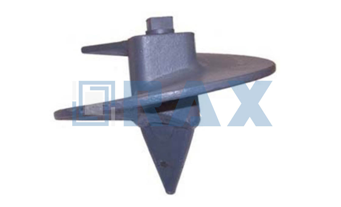
Selecting the correct shaft diameter (e.g., 1-1⁄4-inch) and helix size is a mathematical exercise in load distribution. The holding capacity of a no-wrench screw anchor relies on the surface area of its forged triple-eye rod and welded helix plates engaging the soil matrix. When soil classes dictate lower resistance, increasing the helix diameter becomes necessary to capture a larger volume of stable earth.
Once the physical dimensions are optimized for load distribution, the next step is to calculate the actual capacity based on material limits. This requires translating the anchor’s ultimate breaking load into a practical safe working load for your specific application.
Once the physical dimensions are optimized for load distribution, the focus shifts to calculating the actual performance limits of the installed anchor. This requires translating those mechanical specifications into safe operational parameters for your specific grid infrastructure.
While shaft geometry dictates the physical holding capacity, determining the safe working load requires a different calculation approach. You must then apply manufacturer-provided ultimate breaking loads and standard safety factors to ensure grid infrastructure stability.
To determine the safe working load for your grid infrastructure, always start with the anchor’s ultimate breaking load provided by the manufacturer. Apply a standard safety factor of 2:1 to 3:1 depending on regional utility codes. However, remember that the rated capacity assumes perfect installation. Any deviation in alignment introduces lateral stress that bypasses the anchor’s designed vertical pullout strength.
Installation Alignment and Torque Verification
Theoretical load capacity is strictly conditional upon adherence to precise installation protocols. The holding capacity of a screw anchor is only valid when the guying mass is aligned within a strict 5° tolerance. If the anchor is driven at an angle—even slightly—the load vector changes from a pure axial pullout force to a complex bending moment. This lateral bending concentrates stress on a tiny fraction of the helix plates, leading to premature pullout or catastrophic rod failure.
Furthermore, the method of installation plays a critical role in achieving those theoretical numbers. When installed via machine-driving methods, the anchor achieves full rated load due to consistent soil compression and alignment. However, manual hand-installation inherently carries a variance. Field data indicates that poor hand installation practices can reduce the effective holding capacity by approximately 10% to 20%. Therefore, relying on torque measurements during the drive process is the most reliable field test to confirm the anchor has engaged the necessary soil density for the designated load class.
| Installation Method | Holding Capacity | Alignment Tolerance | Key Advantage |
|---|---|---|---|
| Machine-Driven | Full Rated Load | Within 5° of guying mass | Optimal soil engagement and maximum strength |
| Hand-Installed | Reduced by 10-20% | Strict 5° alignment required | Accessible for remote or small-scale sites |
Installing Anchors with Power or Manual Tools
Power vs. Manual Installation Protocols
Selecting between manual and power installation for no-wrench screw anchors dictates the project timeline, required labor density, and soil penetration capacity. The defining structural advantage of this system is its versatile eye rod termination—featuring large-eye designs—which accommodates standard turning bars for hand-driven projects and hydraulic adapters for rotary drilling rigs, effectively eliminating the need for specialized wrenches.
For manual installation, operators insert a heavy-duty turning bar through the anchor eye to mechanically drive the helix into the ground. This method is highly effective in soft to medium soils but typically caps out at lower torque limits due to human physical constraints. Conversely, power installation utilizes standard hole-boring machine adapters that attach directly to the anchor’s eye. By mounting the anchor onto the hydraulic auger, installers can achieve high-speed rotation, allowing the anchor to be screwed deep into hard-packed clay, rock, or frozen earth where manual torque is insufficient.
📋 Power Installation Specifications & Limits
During rotary drilling installation, strict vertical alignment is mandatory. If the auger is forced down at an angle, the steel shaft can bend, permanently ruining the anchor’s load-bearing capacity. The “7 to 1” rule applies strictly here: the vertical distance from the anchor to the pivot point of the drill rig must be maintained at a ratio of at least 7 to 1 relative to horizontal deviation. Forcing an angled installation destroys the thread engagement and compromises the ultimate holding strength.

Why No-Wrench Anchors Beat Traditional Systems
In modern utility construction, no-wrench screw anchors drastically outperform traditional concrete deadmen or wedge anchors by eliminating manual excavation and tool dependency, ensuring faster deployment and predictable load capacities.
The electric distribution industry has heavily shifted away from traditional cast-in-place concrete deadmen and basic expansion systems. The primary driver is not just material performance, but the severe logistical bottleneck that excavation and curing times introduce to large-scale grid projects. Traditional methods require digging precise holes, placing heavy concrete forms, and waiting days for structural integrity, which stalls project timelines and ties up heavy machinery.
No-wrench screw anchors solve this by acting as a direct-insertion alternative. These systems combine a high-strength helix with a specialized turning eye rod, allowing the anchor to be screwed directly into the earth using mechanical torque. This eliminates the need for shoring, wet concrete, and extended curing periods, providing immediate load-bearing capabilities the moment installation is complete.
Eliminating Labor Dependencies
Traditional guy wire systems often rely on wedge or expansion anchors that strictly require wrenches and specialized rigging equipment to achieve proper tensioning and seating. In remote terrain or adverse weather conditions, relying on hand tools is inefficient and prone to human error.
A true no-wrench design incorporates a forged rod (such as a triple-eye or thimble-eye configuration) that features a generously sized opening. This engineering allows installers to simply insert a turning bar or a socket adapter to rotate the anchor deep into the soil. By removing the requirement for heavy-duty torque wrenches during the installation phase, field crews can work significantly faster and with fewer personnel.
Predictable Load Performance in Varying Soils
Concrete deadmen suffer from unpredictable holding power if the soil compacts unevenly around the form. In contrast, no-wrench screw anchors derive their holding capacity from the bearing area of the helical plates against the undisturbed soil strata.
This mechanism provides a highly predictable pull-out strength based on standard geotechnical calculations. Furthermore, these anchors are typically manufactured using drop-forged steel components rather than standard casting. The forging process aligns the grain structure of the metal, providing superior tensile strength and resistance to sudden shock loads compared to brittle cast iron alternatives.
Immediate Structural Integrity
One of the most critical failures in traditional pole-line hardware installation is the delay in securing conductors after a pole is set. If crews wait for concrete to cure before guy-wiring, the pole remains vulnerable to wind or accidental impact.
Screw anchors provide immediate structural anchorage. Once the anchor is torqued to the specified depth in firm soil, the utility line can be tensioned and secured instantly. This capability allows contractors to meet strict deadlines and reduces the window of vulnerability during the construction phase.
| Feature | Specification | Advantage |
|---|---|---|
| Anchor Type | No-Wrench Screw Anchor vs. Traditional Wedge/Expansion | Tool-free installation eliminates labor costs and equipment dependency |
| Rod Construction | Forged Triple-Eye Rod vs. Standard Casting | Aligned grain structure prevents snap-offs under extreme wind loads |
| Dimensional Tolerance | Strict 1mm Accuracy vs. Loose Casting Variance | Ensures precise extension rod coupling and secure fitment |
| Corrosion Protection | Hot-Dip Galvanizing >85 Microns (ISO 1461/ASTM A123 Class C) vs. Standard Coating | Superior long-term durability in harsh environmental conditions |
| Quality Assurance | 100% Double-Review & SGS Verified vs. Random Sampling | Guarantees consistent high-breaking load performance for global utilities |
Ensuring Long-Lasting Corrosion Resistance
Standards-Compliant Hot-Dip Galvanizing Specifications
To ensure long-lasting corrosion resistance for outdoor utility infrastructure, the industry standard for steel hardware is hot-dip galvanizing that strictly complies with ISO 1461. This process involves immersing cleaned steel into molten zinc to create a metallurgical bond between the metal and the coating. High-grade manufacturing facilities prioritize a mean coating thickness exceeding 85 microns. While some market competitors may deliver thinner coatings to cut costs, maintaining this 85-micron benchmark ensures adequate protection against aggressive environments.
Environmental Factors and Soil pH Risks
Galvanic longevity is not solely determined by the zinc weight but heavily depends on the surrounding environment. When installing anchors or clamps, engineers must account for soil acidity (pH levels). Steel corrodes rapidly if the soil pH drops below 5.5 or rises above 12.0. Standard galvanized coatings perform exceptionally well in neutral soils but require rigorous quality control—such as SGS testing and double-review inspection protocols—to guarantee uniform coverage before deployment in these extremes.
ASTM Compliance and Material Durability
Reliable corrosion resistance requires utilizing hot-dip galvanized finishes that adhere to American Society for Testing and Materials (ASTM) A-153 or ASTM A123 standards. These specifications define the minimum weight of zinc required for various steel thicknesses. Drop-forged steel components, such as no-wrench screw anchors or helical piles, benefit significantly from this treatment. The forging process creates a dense grain structure that, when combined with a certified ASTM-compliant zinc layer, provides superior mechanical strength and rust resistance compared to traditional casting methods.
Fixing Common Installation Problems
Correcting Torque Loss During Installation
Torque loss in helical screw anchors does not result from soil friction overcoming the anchor, nor does it cause the unit to “spin back” into the ground. Torque loss occurs when there is a mechanical failure at the coupling interface between the main anchor rod and an extension rod. This disengagement often happens because of dimensional inaccuracies in generic cast couplings that fail to maintain a tight tolerance fit.
- Dimensional Precision: Our automated production maintains a strict 1mm tolerance across all components, ensuring that extension rod couplings slide perfectly onto the anchor shaft without excessive clearance.
- Forged vs. Cast Integrity: Standard cast eye rods often contain microscopic internal voids that weaken the coupling mechanism under high driving torque. We utilize drop-forged steel for our triple-eye rods, aligning the grain structure to withstand the mechanical stress of installation.
- Visual Verification: Inspecters should look for smooth transitions at the coupling point. If the fit feels loose, the anchor risks decoupling during the final driving phase, leading to installation failure.
Addressing Rod Deflection and Alignment Issues
Rod deflection typically originates from misalignment during the initial penetration phase. When the anchor is not driven vertically—or at the precise angle specified by the engineering drawing—the helix blades encounter uneven soil resistance. This lateral force bends the shaft rather than penetrating it. A bent shaft compromises the structural rigidity required to support utility pole loads.
- Blade Geometry: High-quality anchors feature precisely cut helix blades. Uneven blade angles create drag on one side of the shaft, pulling it out of alignment.
- Shaft Straightness: Rax Power subjects every piece to a double-review process with 100% pre-packaging inspection to guarantee straightness. Bent or warped rods are rejected before they ever leave the factory.
- Installation Technique: Ensure the hydraulic power head is aligned directly over the pilot tip. Forcing a deflected rod only exacerbates the bend; the correct procedure is to extract the anchor and restart with proper vertical alignment.
Maintaining Load Integrity Under Stress
Load integrity depends entirely on two factors: the mechanical strength of the coupling and the corrosion resistance of the steel matrix. If the galvanizing layer is compromised—either by poor application or physical damage during transport—the anchor becomes vulnerable to rapid degradation in aggressive soils. additionally, without Strong forged connections, the anchor cannot transfer the full pull-out load from the pole to the deep soil strata.
- Galvanizing Compliance: All products undergo hot-dip galvanizing compliant with ISO 1461 and ASTM A123 standards, boasting a mean coating thickness exceeding 85 microns. This barrier prevents rust from eating away at the load-bearing cross-section.
- In-House Load Testing: We conduct rigorous load testing and gauge testing per IEC 120 internally. This ensures that our anchors consistently meet the breaking load requirements specified for international grid applications.
- Material Strength: By utilizing hot-forging instead of traditional casting, we achieve superior tensile strength and precision. This is critical for markets like Russia and South America, where utility grids demand hardware capable of withstanding extreme environmental stresses.
Conclusion
We have covered how soil class dictates holding capacity and why torque precision matters for utility grid stability. Hot-dip galvanizing per ASTM A123 Class C ensures longevity, but proper installation remains the critical factor. Our engineers at Sapiens AI Manufacturing see too many projects fail due to mismatched extension rods or ignoring soil density variations. We hold 120,000 square meters of production space and maintain ISO 9001 certification to guarantee consistent material quality across every batch. Relying on generic specs leads to costly callbacks and structural failures that damage your reputation. You need anchors engineered specifically for the load conditions you face, not just standard catalog items.
- Confirm your geotechnical report matches our load charts before ordering bulk quantities.
- Check extension rod compatibility with your specific power tools to prevent alignment issues.
- Contact our technical support team for custom engineering advice on complex soil scenarios without any obligation to purchase immediately.
Frequently Asked Questions
What is a no-wrench screw anchor?
A no-wrench screw anchor, also known as a helical pile or screw pile, is a foundation system designed to be installed by rotating it into the ground. It eliminates the need for concrete curing or heavy excavation equipment, allowing for rapid deployment in various soil conditions. This mechanical anchoring method provides immediate load-bearing capacity through friction and bearing on the helical plates.
How deep should screw anchors be installed?
Installation depth depends on soil composition, required load capacity, and frost line considerations rather than a fixed standard. Anchors must extend below the active zone of soil movement and reach stable, high-density layers to ensure stability. Proper depth is verified through torque monitoring and, where necessary, proof loading tests to confirm design specifications are met.
Can screw anchors be used in rock?
Standard helical anchors are not designed for direct installation into solid rock due to the inability of the helices to penetrate hard formations. In rocky terrain, engineers may use pre-drilled holes or specialized rock socketing techniques to install the anchor. Alternatively, surface-mounted foundations or drilled piers might be more suitable alternatives for bedrock conditions.
What is the lifespan of these anchors?
When properly specified and installed, helical anchors can have a service life exceeding 50 to 100 years. The longevity is largely determined by the corrosion protection method and the aggressiveness of the soil environment. Regular inspections and adherence to design standards ensure that the structural integrity remains intact throughout the lifespan of the supported infrastructure.
Do you need permits for installation?
Permit requirements vary by jurisdiction but often depend on the scale of the project and local building codes. Structural engineering calculations and geotechnical reports are typically required to demonstrate compliance with safety standards. Consulting with local authorities early in the planning phase helps identify specific regulatory hurdles and ensures legal installation of the foundation system.