
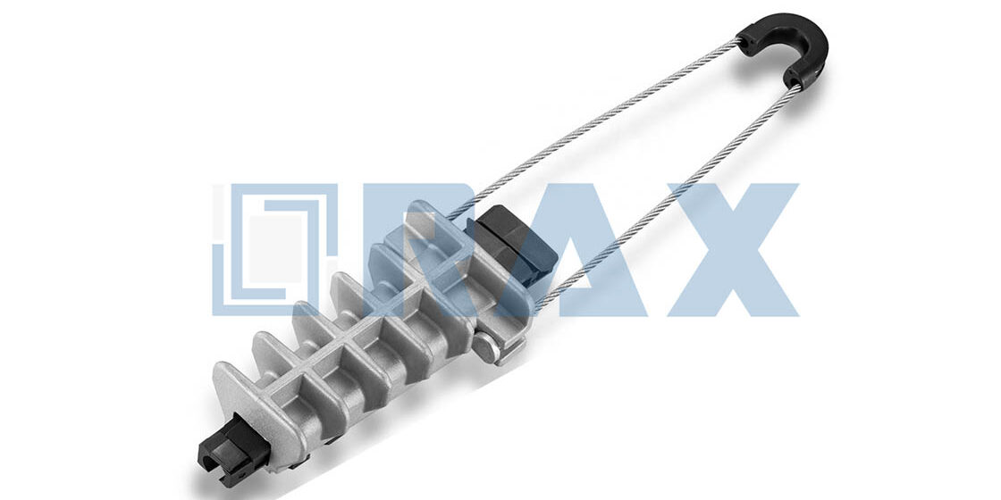
The anchoring clamp functions as the critical load-transfer interface between the guy wire and the no wrench screw anchor. While the rod and helix secure the foundation, the clamp ensures structural tension transfers directly to the soil without slippage or fatigue. If this interface fails, the anchor’s high torque rating becomes irrelevant, putting the entire transmission span at immediate risk.
High-performance anchors can generate significant holding power in stable ground. Some configurations support a maximum installing torque of 2300 ft.-lbs for a 1-1/4 inch diameter rod, meaning the attached clamps must withstand substantial static loads once the wire is tensioned. Pairing high-capacity anchors with low-grade clamps creates a bottleneck that compromises the entire guying system.
We break down the specific material standards and installation tolerances that prevent premature failure, covering hot-dip galvanizing thickness and load testing protocols. You will learn how to identify quality hardware by sight and ensure your clamps meet the rated tensile strength required for utility pole guying.
Understanding No-Wrench Screw Anchors
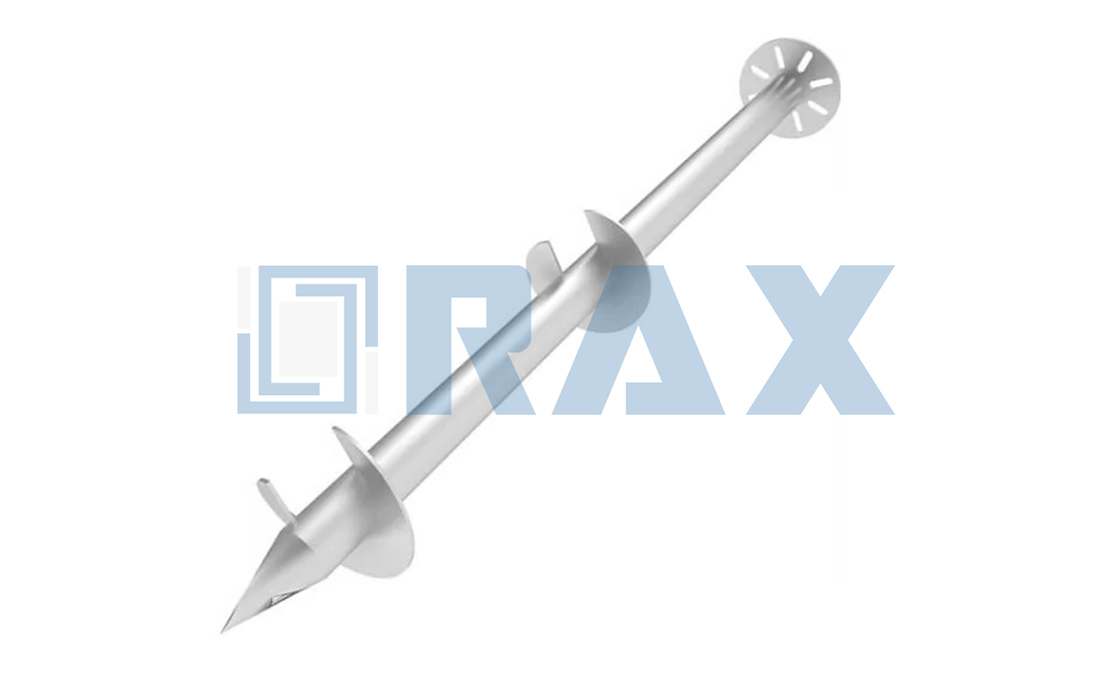
No-wrench screw anchors are manually installed earth anchors that utilize a simple lever bar for deployment rather than hydraulic torque wrenches, offering rapid deployment for utility and solar projects.
Key Components of No-Wrench Screw Anchor Systems
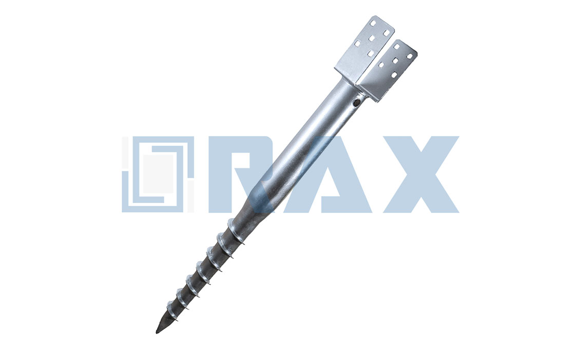
To understand how these anchors secure critical infrastructure, it helps to visualize them as a giant, heavy-duty screw designed specifically for the earth. Unlike traditional concrete foundations that require pouring and curing time, a screw anchor provides immediate holding power upon installation. The system consists of three primary structural elements that work together to transfer tension loads from the structure deep into the soil.
- The Central Rod (Shaft): This is the steel spine of the anchor, typically available in various lengths and diameters depending on the required load depth. It serves as the connection point between the surface hardware and the soil.
- The Helix (Blade): Welded to the bottom of the rod, this is the spiral plate that physically cuts into the ground. The design of the helix determines how effectively the anchor displaces soil to generate holding resistance.
- The Anchor Eye: Located at the top of the rod, this is the attachment point for guy wires or tension clamps. It acts as the critical interface where the load from the pole or cable is transferred to the anchor shaft.
While these components may seem simple, the manufacturing method defines their reliability. We utilize automated hot-forging technology to form the anchor eyes and integral junctions. In our experience, this process creates a denser, more uniform grain structure in the steel compared to traditional casting methods. Cast products can often harbor microscopic voids or weak points that fail under sudden tension spikes; our forged components ensure structural integrity where it matters most—right at the point of load transfer.
Installation Advantages for Utility Pole Projects
The primary distinction of the “no-wrench” anchor lies in its installation philosophy. Standard screw anchors often require heavy hydraulic machinery or torque multiplier heads to drive the helix into the earth. This involves transporting bulky equipment to often remote or difficult-to-access pole sites. The no-wrench variant eliminates this dependency by leveraging mechanical advantage.
Installation crews use a drive bar, often called a “bull bar,” inserted through the anchor eye or a specialized drive boss. By rotating the bar manually, the crew applies consistent torque that drives the helix into the soil. This tool-free approach drastically reduces the logistical burden. There is no need to transport hydraulic power units or wait for specialized crews. For utility projects, this translates to faster completion times and significantly lower labor costs, particularly in areas where vehicle access is restricted.
Soil density directly impacts the installation effort required for these helical anchors. We design our helix configurations to optimize soil displacement, allowing for easier manual installation even in denser earth conditions without sacrificing pull-out resistance.
Common Applications in Power Transmission Infrastructure
No-wrench screw anchors are versatile workhorses in the field. They are predominantly employed in distribution line guying, where they anchor the guy wires that keep utility poles upright against lateral forces. Because they can be installed quickly and set immediately, they are ideal for emergency restoration work where speed is critical.
Beyond traditional power lines, these anchors have found a significant niche in renewable energy infrastructure. In solar farm foundations, they are used to secure the racking systems for photovoltaic panels. The ability to install without concrete pouring reduces the environmental footprint and accelerates the construction timeline for solar arrays. Our OEM capabilities allow us to tailor specific shaft lengths and helix sizes for these diverse applications, ensuring that whether a project is in the frozen soils of Russia or the varied terrains of Southeast Asia, the anchor performs exactly to the site’s geotechnical requirements.
| Feature | Engineering Specification | Operational Mechanism | Performance Advantage |
|---|---|---|---|
| Installation Mechanism | Tool-Free Torque Application | Utilizes a simple lever bar to rotate the anchor into the soil, eliminating the need for heavy hydraulic wrenches. | Drastically reduces installation time and labor costs while maintaining precise placement. |
| Corrosion Protection | ISO 1461 Hot-Dip Galvanizing | Steel components are coated with a zinc layer exceeding 85 microns mean thickness for uniform coverage. | Provides superior resistance to soil corrosion and extends service life in underground environments. |
| Load Bearing | High Tensile Strength | Helical welding and shaft design optimize soil displacement to maximize pull-out resistance, verified by IEC 120 load standards. | Delivers reliable holding power suitable for power transmission and solar foundation stability. |
| Manufacturing Precision | Automated Hot-Forging & Machining | Utilizes advanced automated machinery and hot-forging technology to ensure dimensional consistency and structural integrity. | Eliminates weak points found in cast alternatives, ensuring high reliability under load. |
| Operational Versatility | Multi-Soil Compatibility | Engineered to perform effectively across a range of soil densities without special site preparation. | Offers a flexible, cost-effective anchoring solution for diverse geographic project sites. |
What Does an Anchoring Clamp Do?
The Critical Function of the Anchoring Clamp
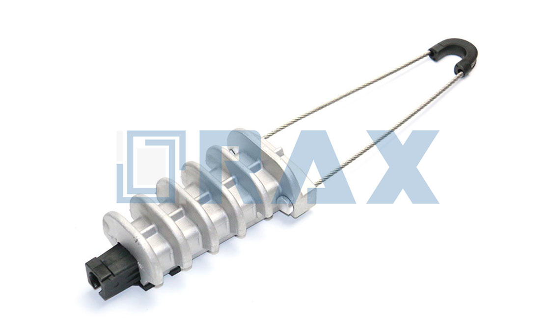
In high-tension overhead line infrastructure, the anchoring clamp serves as the primary structural interface between the guy wire (or cable) and the earth anchor’s eye bolt. It is not merely a connector; it is the mechanical joint responsible for transferring extreme lateral loads from the pole into the ground foundation. Without this component, the tensile force exerted by the guy wire would simply slip out of the thimble or triple-eye connection, causing immediate structural failure of the utility pole.
Utility engineers must prioritize clamp performance under massive continuous tension loads. The primary engineering challenge is preventing wire strand crushing and stress concentrations while maintaining grip under dynamic wind and ice loading. If the clamp applies uneven pressure, it creates “stress concentrations” that can crush the wire strands, leading to fatigue cracks over time. Therefore, the anchoring clamp must distribute force evenly across the contact surface to ensure the conductive strands remain intact.
- Load Transfer Efficiency: The clamp must securely fasten to the specific diameter of the guy wire to ensure 100% of the tension load is transferred to the anchor eye without slippage.
- Corrosion Integrity: Because the clamp sits exposed in harsh weather or buried in acidic soil, it requires robust protection (such as hot-dip galvanizing) to prevent seizing to the anchor eye, which would make future maintenance impossible.
- Strand Protection: The internal surface of the clamp must be designed to maximize friction while minimizing the crushing force applied directly to the individual steel strands of the wire.
Fitting Clamps to No-Wrench Anchors
Engineered Interface: Securing Guy Clamps to Triple-Eye Rods
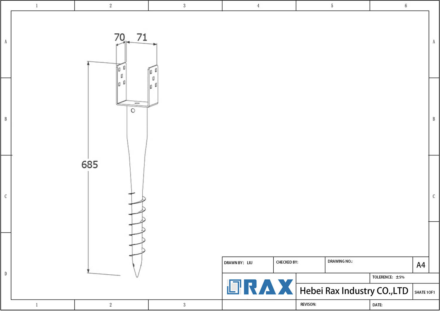
The primary engineering challenge in no-wrench screw anchor systems lies in the physical mating of the guy clamp with the anchor’s eye rod. These anchors are frequently equipped with standardized “Triple Eye” or “Thimble Eye” configurations, which provide large apertures designed for manual turning bars or machine adapters during installation. When installing a guy clamp on these oversized apertures, a standard clamp may simply slide off or fail to generate sufficient friction, creating a critical point of structural failure under high line tension.
To resolve this, procurement and engineering teams must match the clamp’s internal geometry precisely to the anchor’s eye specifications. The clamp must be selected or customized to ensure that when the anchor rod is inserted, the metal-to-metal contact area is maximized to prevent rotation or slippage. This mechanical lock is essential because no-wrench anchors are often buried deep within the earth (sometimes exceeding several meters). Once installed, they cannot be easily adjusted or re-tensioned without specialized heavy machinery.
- Aperture Mismatch Risk: Using a clamp rated for a smaller diameter eye on a 4-inch by 54-inch triple-eye anchor creates a gap. Under wind or ice loading, the guy wire will pull the anchor upward, but instead of transferring the load to the helix, the energy will be dissipated through repeated impact on the anchor rod’s edges.
- Bolt Torque Thresholds: High-tensile hardware used to secure the clamp to the triple-eye rod must be torqued strictly according to manufacturer standards. Insufficient torque allows the clamp jaw to shift microscopically, which can lead to galvanic corrosion or metal fatigue over time.
- Load Transfer Dynamics: The connection point between the clamp and the eye must be capable of handling the anchor’s maximum design pullout capacity. For heavy-duty utility poles or solar farm arrays, this can range significantly based on soil class, requiring robust steel-to-steel clamping force rather than relying solely on friction.
Identifying the Clamp by Sight
Visual Distinction: Bolted Clamps vs. Preformed Grips
Procurement teams and field inspectors can quickly categorize overhead line hardware by visual inspection. Bolted guy clamps are rigid metal assemblies, typically featuring a curved saddle and a U-bolt or two separate bolts crossing each other, requiring traditional nuts and wrenches for installation. In contrast, preformed guy grips resemble heavy-duty springs or coils that wrap around the wire without the use of traditional nuts or bolts, necessitating different handling and tool requirements.
Quick Visual Rule: If it has nuts and bolts and looks like a “C” or “U” shape, it is a bolted clamp. If it looks like a woven spiral or wire mesh, it is a preformed grip.
Analyzing Bolted Clamp Geometry
The load rating and application of bolted guy clamps are revealed through specific physical characteristics. Key visual indicators include the bolt configuration, saddle thickness, and groove radius to determine clamp quality and wire compatibility. Standard clamps typically feature two bolts running perpendicular to each other to create a locking force, while high-strength variants may utilize larger diameter bolts or a thicker saddle body. Inspectors should look closely at the groove radius—the inner curve where the wire sits. A smooth, uniform groove indicates a proper match for the wire diameter, whereas a deformed or mismatched groove suggests the risk of damaging the cable strands or causing slippage under load.
- Saddle Shape: Look for a deep, curved “bow” that contacts at least 50% of the wire’s circumference for even pressure distribution.
- Bolt Diameter & Thread: Heavier duty clamps will visibly feature thicker shanks (e.g., 16mm or 5/8″) and finer or more robust threading to resist vibration loosening.
- Keeps (Nail Stops): Many clamps include small protrusions or “keeps” on the saddle to prevent the guy wire from slipping out before tension is applied. Visually verifying the presence of keeps is a quick quality check.
Sizing Clamps by Wire Diameter Compatibility
Incorrect sizing is a common failure point in line construction. While there is no universal color code for bolted clamps, size is visually determined by the span of the jaws. A clamp intended for a 3/8-inch wire will have a noticeably tighter throat gap than one designed for a 5/8-inch wire. For preformed grips, manufacturers often utilize color coding on the rods or the packaging label (e.g., yellow for one size, red for another). When identifying preformed products by sight, count the number of rods; larger diameter cables often require grips with more rods to distribute the holding force effectively.

Materials Built to Resist Corrosion
The Science of Corrosion Resistance in Pole Line Hardware
Corrosion represents the primary threat to the longevity of overhead power transmission infrastructure. Consequently, material choice and surface treatment are critical differentiators between durable grid upgrades and costly emergency replacements in harsh environments. These specifications ensure that hardware remains structurally sound for decades, even when exposed to coastal salt spray or industrial pollution.
Material Selection: Carbon Steel vs. Aluminum
The core component of most heavy-duty pole line hardware, such as earth anchors and clamps, is forged steel. While aluminum is lighter, it lacks the high tensile strength required to secure heavy utility poles against strong winds or ice loads. Therefore, high-strength carbon steel is the industry standard for the base material.
- Tensile Strength: Carbon steel provides the necessary breaking load capacity (often exceeding several tons) to anchor guy wires securely.
- Structural Integrity: Unlike cast metal, hot-forged steel eliminates microscopic voids, ensuring the anchor does not snap under extreme torque during installation.
The Galvanizing Standard: A Protective Barrier
Since bare steel rusts rapidly, it must be protected. The gold standard for protecting steel hardware is Hot-Dip Galvanizing (HDG). This process involves cleaning the steel and immersing it in molten zinc. The result is a metallurgical bond where the zinc acts as both a barrier and a sacrificial anode—if the coating is scratched, the zinc corrodes first, saving the underlying steel.
Do not confuse “electro-galvanizing” with “hot-dip.” Electro-galvanizing creates a thin, shiny layer (often less than 15 microns) that offers poor long-term protection. For outdoor pole lines, only Hot-Dip Galvanizing meets durability requirements.
Key Specifications for Longevity
B2B procurement requires adherence to specific international standards rather than vague durability claims. Generic descriptions like “rust-resistant” are insufficient for professional specifications. The following concrete metrics define true corrosion resistance:
- Coating Thickness: High-quality galvanized parts typically feature a mean coating thickness exceeding 85 microns. Thinner coatings degrade faster in abrasive soil conditions.
- Standard Compliance: Look for compliance with ASTM A123 (for steel hardware) or ISO 1461. These standards dictate the minimum weight and adhesion of the zinc layer.
- Surface Finish: A proper HDG finish should be smooth and bright. Dripping, rough, or flaky zinc indicates poor manufacturing quality control and will fail prematurely.
Preventing “Galvanic Corrosion”
A critical engineering pitfall is galvanic corrosion. This occurs when two different metals (like steel and copper) touch in the presence of an electrolyte (like rainwater). Because they have different electrical potentials, the more reactive metal (the steel anchor) will corrode much faster than usual. To prevent this, ensure that all hardware components in a single assembly are of the same material type or are properly insulated from dissimilar metals.
How to Install the Clamp
To prevent such failures, it is essential to understand the mechanical installation process that secures these components. Proper clamp installation ensures structural integrity while maintaining the necessary separation to avoid galvanic corrosion.
Installing a clamp on a no-wrench screw anchor is a high-stakes operation where a single misalignment can compromise the entire pole line. Unlike traditional anchors that require tools to twist into the ground, the no-wrench design relies on a pre-fabricated hot-dip galvanized hex shank and a specific eye or thimble configuration for tensioning. The “no-wrench” feature applies strictly to the anchoring process itself; once the anchor is screwed in by hand, the clamping and tensioning phase demands precision mechanical connections.
The primary pain point for installers is connecting the suspended guy wire strand to the anchor’s eye without introducing lateral shear stress. If the strand is not pulled taut before the final clamp is secured, the hardware can loosen under wind load. Furthermore, standard U-bolt wire rope clips are fundamentally unsuited for this connection because they cannot accommodate the curved geometry of the anchor eye or the required turnbuckle assembly.
The Correct Connection Method
To safely attach the clamp, you must bridge the gap between the helical anchor’s thimble eye and the suspended cable using a turnbuckle assembly or a dedicated dead-end grip. This method ensures that the tensile force is transferred linearly along the axis of the wire, which is how these components are engineered to handle load.
📋 Actionable Steps
- Step 1: Secure the Anchor Eye. Once the no-wrench anchor is fully seated in the soil (typically by hand-threading it into a pre-drilled hole), ensure the exposed galvanized eye or triple-eye shackle is completely clear of soil and debris. Do not attempt to pull or wrench the anchor at this stage, as the threads are designed to hold static loads immediately upon seating.
- Step 2: Insert the Thimble and Form the Loop. Place a steel or synthetic thimble inside the loop of the guy strand. This maintains the shape of the loop and prevents the wire from kinking or being crushed when tension is applied. Thread the strand through the anchor’s eye.
- Step 3: Attach the Turnbuckle. Connect one end of a turnbuckle to the anchor eye using a clevis pin or a specific guy clamp rated for the strand diameter. Connect the other end of the turnbuckle to the thimble loop. This assembly allows you to mechanically tighten the guy wire by rotating the turnbuckle body.
- Step 4: Tension and Finalize. Tighten the turnbuckle until the guy wire reaches the specified tension (measured in pounds or kilograms). Ensure the pole is perfectly plumb before locking the turnbuckle nuts. Finally, secure the wire loop to the thimble using approved cable clamps or a mechanical swaging sleeve.
Common Installation Pitfalls
A frequent error involves attempting to splice the wire directly onto the anchor eye without a turnbuckle or proper gripping hardware. Without the ability to adjust tension, environmental expansion and contraction will lead to immediate slackness in the line. Additionally, mixing incompatible materials—such as using aluminum fittings with steel strands—can cause galvanic corrosion, weakening the joint over time.
Never use standard U-bolt wire rope clips directly on the anchor eye. These clips are designed for splicing wires together, not for transferring load from a solid metal shackle. Using them here creates a dangerous point of failure where the bolt can shear off under lateral load. Always use hardware rated for the specific breaking strength of your guy strand.
Verification of Hardware Compatibility
Before beginning the physical installation, verify that the clamp or grip matches the exact diameter of your guy wire. No-wrench anchors often feature triple eyes of varying sizes. Ensure your selected clamp is compatible with the specific eye size you are utilizing. Mismatched hardware can slip during the tensioning process, leading to catastrophic pole collapse.
- Diameter Match: The inner radius of the clamp must snugly fit the strand to prevent crushing the individual wires.
- Galvanization Check: Ensure the clamping hardware has a similar hot-dip galvanized finish to the anchor to prevent electrolytic degradation at the contact points.
- Load Rating: Verify the clamp’s working load limit exceeds the maximum expected tension of the guy wire, typically requiring a safety factor of at least 3:1 for utility applications.
Ensuring Structural Integrity Through Testing
In-House Load Testing Protocols for Clamps
Validating hardware performance under controlled stress prevents catastrophic field failures and ensures compliance with international safety standards.
Mechanical strength is non-negotiable for anchoring clamps in utility infrastructure. These components serve as the critical link between the anchor rod buried in the soil and the guy wire securing the pole. If a clamp yields under tension, the entire stability of the overhead line is compromised. To mitigate this risk, rigorous load testing is essential to simulate the extreme tensile forces that occur during severe weather events, such as heavy ice loading or high winds.
While visual inspections can identify surface defects, they cannot predict the behavior of the metal grain structure under stress. We conduct in-house load testing that pushes clamps beyond their standard working limits to verify their breaking load. By adhering to IEC 120 standards, our testing protocols replicate the “worst-case scenario” in a controlled environment. This ensures that when the clamp is installed in the field, its structural integrity has already been proven to withstand significant deformation without failure, providing engineers with the data needed to specify the correct safety factors for their projects.
Galvanizing Standards and Corrosion Resistance
Corrosion is the primary long-term threat to pole line hardware. Once a clamp is installed, it is exposed to harsh elements, including acidic rain, industrial pollutants, and soil chemicals. Over time, oxidation can eat away at the steel, reducing the cross-sectional area and weakening the load-bearing capacity. To combat this, the application of a protective coating is just as critical as the steel grade itself.
Hot-dip galvanizing is the industry benchmark for corrosion protection, creating a metallurgical bond between the zinc and the steel that is far superior to simple electroplating or paint. We strictly follow ISO 1461 standards to ensure that every batch of hardware achieves a consistent, robust coating. This process not only seals the surface against moisture but also provides cathodic protection, meaning the zinc will sacrificially corrode to protect the underlying steel even if the surface is scratched. Our focus is on delivering a finish that remains smooth and bright, ensuring that the hardware resists “white rust” and maintains its structural performance for decades in the field.
Quality Control Inspections Before Packaging
The final stage of the manufacturing process is where consistency is either guaranteed or lost. For B2B procurement, receiving a shipment with dimensional variances can be a logistical nightmare, causing installation delays on-site. A tolerance error of just a millimeter can prevent a U-bolt from fitting a pole band or a clamp from gripping the wire correctly. Therefore, pre-packaging inspection is the last line of defense against non-conforming products leaving the factory floor.
We implement a zero-tolerance policy for dimensional accuracy through our double-review process. Every single unit passes through two distinct inspection checkpoints before it is boxed. Our dedicated QC team utilizes calibrated gauges to verify critical dimensions, ensuring that the threads run smoothly and the fitment is precise. This 100% inspection rate might seem labor-intensive, but it drastically reduces the return rate and downtime for our clients. By catching defects at the source, we ensure that the hardware arriving at a utility project site is ready for immediate installation, eliminating the need for on-site sorting or rework.
| Testing Parameter | Standard | Method | Outcome |
|---|---|---|---|
| Load Capacity Verification | IEC 120 | In-house Rigorous Load Testing | Ensures structural integrity under extreme tensile stress |
| Dimensional Accuracy | IEC 120 | Double-Review Inspection (100% of Products) | Maintains strict dimensional accuracy for precise fitment |
| Corrosion Resistance | ISO 1461 | Hot-Dip Galvanizing Coating Thickness Check | Mean coating >85 microns for long-term durability |
| Material Integrity | SGS Verified | Hot-Forging vs. Casting Strength Analysis | Superior grain structure and high-breaking load capacity |
Conclusion
The lifespan of an anchor system depends heavily on the integrity of its galvanizing coating. Superior grain structure and high-breaking load capacity are critical, as your anchor system lives or dies on the clamp connection. An anchoring clamp for no wrench screw anchor transfers massive tensile loads directly from guy wires into the helical earth anchor. You must verify hot dip galvanized screw anchor coating thickness meets the mean coating thickness exceeding 85 microns before installation. Galvanizing standards and corrosion resistance dictate the lifespan of utility pole projects in harsh environments. Our engineering team maintains strict quality control inspections before packaging to ensure structural integrity through testing protocols. Confirm ASTM A123 compliance on all delivered hardware.
- Confirm ASTM A123 compliance on all delivered hardware.
- Check anchor rod coupler tolerance for galvanizing gaps.
- Verify installation torque matches soil class requirements.
Frequently Asked Questions
Why use clamps instead of eye bolts?
Clamps offer superior adjustability and secure gripping compared to fixed eye bolts. They can accommodate slight variations in cable diameter and provide a more uniform distribution of pressure along the grip area. This reduces the risk of slippage and minimizes damage to the cable strands during high-load conditions.
What is the typical load capacity?
Load capacity depends on the anchor’s design, soil type, and installation depth rather than just the clamp itself. Clamps are rated for specific tensile strengths to match the guy wire’s Rated Tensile Strength (RTS). Proper system design ensures the entire assembly, including the clamp, handles expected wind and ice loads safely.
How is clamp size determined?
Clamp sizing is based on the outer diameter of the cable or wire rope being secured. Engineers must select a clamp that matches the cable’s specifications to ensure optimal friction and load-bearing capacity. Using an undersized clamp can lead to slippage, while an oversized one may fail to grip effectively.
What is the installation torque requirement?
Installation torque varies by manufacturer and clamp design but generally requires precise tightening to achieve rated strength. Over-tightening can deform the cable or strip threads, while under-tightening causes slippage. Adhering to engineering guidelines ensures the clamp maintains its structural integrity under dynamic loads.
What standards govern these components?
Manufacturing and testing often adhere to international standards such as IEC for electrical equipment and ISO for galvanizing processes. These standards ensure consistency in mechanical strength, corrosion resistance, and dimensional accuracy. Compliance with these regulations is critical for utility projects requiring certified infrastructure components.