
Transmission lines don’t fail because of gravity; they fail because of fatigue. Aeolian vibration eats away at conductor stress points, turning a billion-dollar asset into a liability in under a decade. Rax Industry’s analysis of field failures confirms that ignoring this micro-vibration at suspension clamps is the primary cause of premature conductor downtime.
Properly specified preformed armour rods provide a strength retention level of no less than 95% of the original conductor, ensuring the mechanical integrity of the line isn’t compromised at the critical suspension points. We will examine how aluminum alloy compositions protect ACSR and AAAC conductors against abrasion and bending, plus why matching the rod lay direction is non-negotiable for longevity. You will learn how to select a suspension system that mitigates vibration fatigue rather than just masking it.
What Exactly Is an Armour Rod?
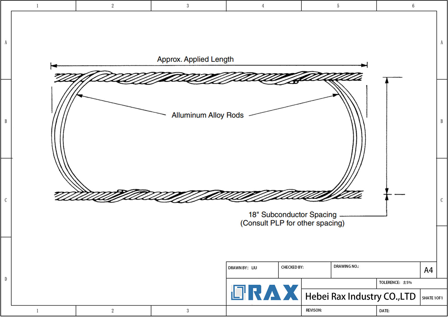
An armour rod is a preformed, helical rod engineered to wrap around a conductor, distributing suspension stress to prevent fatigue and abrasion.
The Physics of the Spiral Helix Structure
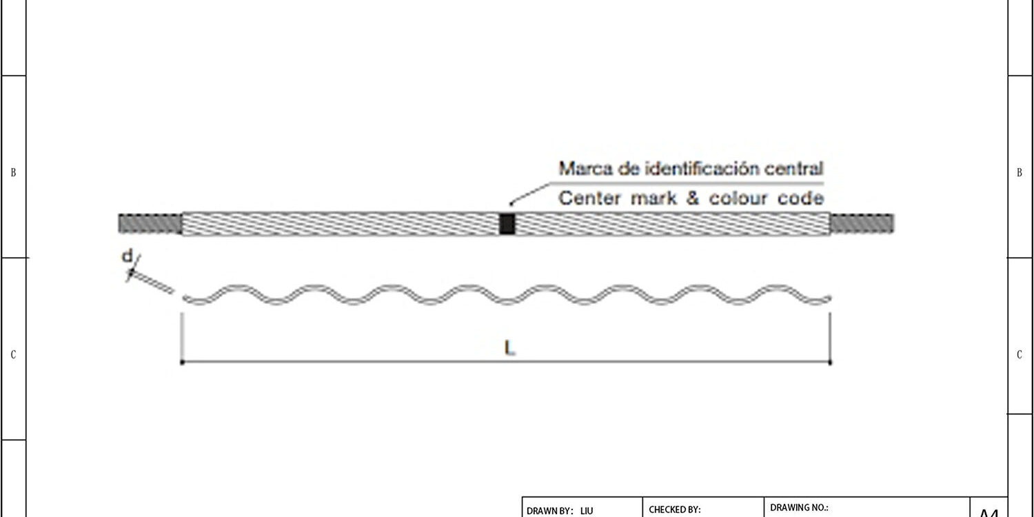
Visually, an armour rod does not look like typical hardware; it resembles a stretched spring or a corkscrew. This “preformed” helical geometry is the core of its engineering. Unlike traditional bolted clamps that pinch a conductor at specific points, the spiral structure maintains continuous contact along its length. When installed, the helix strands interlock to create a unified grip that distributes the load evenly across the conductor’s surface.
Think of it this way: a bolted clamp focuses pressure on two sides of the wire, creating stress peaks. The spiral structure acts like a splint, hugging the entire circumference. This design allows the assembly to withstand Aeolian vibration—wind-induced high-frequency oscillations—without fretting or cutting into the conductor. From a manufacturing perspective, ensuring this helical shape retains its “memory” is critical. If the rod loses its preformed curvature, it cannot maintain the necessary grip pressure. We rely on automated forming machinery to guarantee that every rod leaves the factory with the precise helical pitch required to snap securely onto the cable without deformation.
Aluminum Alloy Material Composition
The choice of material is not arbitrary; it is dictated by electrochemistry. Armour rods are typically manufactured from high-strength aluminum alloy. This selection is driven by the need for galvanic compatibility with the conductor itself. Since most overhead conductors (AAC, AAAC, ACSR) are aluminum-based or aluminum-clad, using a steel rod would create a dissimilar metal reaction. In the presence of moisture, steel and aluminum would essentially act like a battery, leading to rapid galvanic corrosion of the conductor.
By matching the aluminum alloy of the rod to the conductor, we ensure electrochemical stability, preventing corrosion that could compromise the line’s integrity decades down the road. Furthermore, the alloy must be soft enough not to abrade the conductor during installation but hard enough to resist impact from debris or ice. Our quality control protocols involve rigorous chemical composition analysis to ensure that the alloy rods meet these dual requirements of hardness and conductivity.
The Engineering of Diameter Matching
There is no such thing as a “universal” armour rod. The relationship between the rod’s inner diameter and the conductor’s outer diameter is a zero-sum game. The helical rod is manufactured with a slightly smaller inner diameter than the conductor it is meant to protect. This “undersizing” is intentional; as the rod is wound around the conductor, it is forced open, creating a spring-like tension that clamps the assembly securely.
- Too Large: If the rod diameter is too big, the necessary clamping force never develops. The rod will sit loosely on the conductor, failing to dampen vibration and potentially sliding out of position.
- Too Small: If the rod is too small, the installation forces become excessive. This can damage the outer strands of the conductor during the winding process or overstress the armor rod material, leading to premature fatigue cracks.
This is why accurate specification is non-negotiable. We provide detailed sizing charts that map specific rod codes to exact conductor diameters. In our experience, many field failures trace back to “close enough” substitutions. The industry standard requires a precise fit, and we adhere to strict tolerance controls to ensure that when our rod is specified for a conductor, the interference fit provides optimal protection without compromising the cable’s structure.
| Feature | Specification | Advantage |
|---|---|---|
| Primary Function | Mechanical protection and vibration damping for overhead conductors | Prevents fatigue failure and abrasion at suspension points |
| Material Composition | High-strength aluminum alloy with preformed helical strands | Ensures compatibility with conductor materials and corrosion resistance |
| Installation Method | Hand-wound or power-driven helical application without tools | Provides uniform stress distribution and secure grip on various diameters |
| Compliance Standards | IEC 61284 / ASTM F719 tested for mechanical strength | Guarantees reliability under extreme environmental loads and vibrations |
| Service Life | Designed for 40-50 years of maintenance-free operation | Reduces long-term OPEX by eliminating frequent hardware replacements |

Why You Need Armour Rods
Armour rods act as a critical mechanical buffer for overhead conductors, protecting expensive aluminum strands from fatigue and abrasion at suspension points.
In the harsh environment of overhead power lines, conductors are subjected to relentless physical stress. An armour rod serves as a hardened sleeve that covers the vulnerable transition zone where the rigid hardware meets the flexible conductor. This component is not merely an accessory; it is the primary defense mechanism against the two most common causes of premature line failure: aerodynamic vibration and structural friction.
Preventing Aeolian Vibration Fatigue
Even in moderate wind conditions, overhead lines experience a phenomenon known as Aeolian vibration. This occurs when steady wind flows across the line, creating vortices that induce a standing wave pattern on the conductor. Think of this like air blowing over the opening of a bottle to create a musical note—the conductor “sings” in specific frequencies.
While spiral vibration dampers are designed to absorb energy further down the span, they cannot fully mitigate the high-frequency oscillations right at the suspension point. Without protection, these constant micro-movements cause the individual aluminum strands of the conductor to bend back and forth until they undergo metal fatigue. An armour rod mitigates this by stiffening the conductor temporarily over its length. By increasing the rigidity of the protected section, it shifts the resonant frequency out of the problematic range, effectively stopping the fatigue process before it starts.
- Vortex Shedding: Wind creates alternating pressure waves that lift the conductor up and down.
- Fatigue Failure: Rapid bending at the clamp edge cracks aluminum strands.
- Rigidity Buffer: The pre-formed armour rod locks strands together to resist localized bending.
Distributing Suspension Point Stress
The suspension clamp is responsible for holding thousands of pounds of tension. When a clamp applies direct pressure onto the soft aluminum strands of a conductor, it creates a massive concentration of stress. Over time, this crushing force permanently deforms the wires, reducing the overall cross-sectional area and electrical carrying capacity of the line.
Effective load distribution relies on the specific mechanical interaction between the armor rod and the conductor. An armour rod acts as a specialized load distributor. Because it is manufactured with a slightly smaller inner diameter than the conductor itself, it creates an interference fit and clamping force. When the suspension clamp grips the armour rod rather than the conductor directly, the immense mechanical tension is spread evenly across the surface of the rod. This distributes the crushing force across dozens of contact points instead of just a few tight grooves.
- Pressure Distribution: Spreads the clamp’s grip over a wider surface area.
- Strand Preservation: Prevents the crushing and flattening of delicate outer aluminum wires.
- Structural Integrity: Maintains the geometric shape of the conductor under heavy tension.
Protecting Against Surface Abrasion
During the installation phase, conductors are pulled through pulleys and past guide wires. This process subjects the conductor to severe frictional forces that can strip away the protective oxide layer and abrade the aluminum strands. Once the outer layer is compromised, the exposed inner steel core (in ACSR conductors) is highly susceptible to rapid corrosion, leading to catastrophic line failure years later.
Furthermore, the electrical clearance between the hard hardware and the wire creates microscopic movement during storms. This fretting action generates conductive dust that can bridge gaps and cause flashovers. The armour rod provides a sacrificial, highly abrasion-resistant barrier that takes the brunt of both installation friction and long-term operational rubbing. In our engineering assessments, we consistently find that lines installed with properly sized armour rods require significantly less maintenance intervention over a 40-year lifecycle compared to those relying solely on bare hardware.
- Installation Friction: Protects wires from damage during pulling and stringing operations.
- Fretting Corrosion: Stops wear caused by wind-induced rubbing between the wire and the clamp.
- Oxide Layer Defense: Preserves the natural corrosion resistance of the conductor surface.

Where to Use Armour Rods
Primary Installation Zones on Transmission Lines
The most critical application for preformed armour rods is at mechanical suspension points where the overhead conductor is clamped to suspension hardware. Without these rods, the rigid metal grip of the clamp digs into the aluminum strands, creating high-stress concentration zones that lead to rapid fatigue and structural failure. By wrapping a helical aluminium alloy rod around the conductor before installing the suspension clamp, you effectively distribute the crushing load across a much wider surface area.
This is particularly vital for All-Aluminium Alloy Conductors (AAAC) and Aluminum Conductor Steel Reinforced (ACSR) lines. In these systems, the exterior strands are pure aluminum or aluminum-clad steel, which are significantly softer than the galvanized steel core. The armour rod acts as a sacrificial buffer, ensuring the internal steel core remains uncompromised while the outer strands are protected from abrasion and bending stress.
Conductor Material Compatibility & Sizing
Correct deployment requires matching the armour rod material to the conductor type. For phase conductors made of aluminum alloys, using a standard aluminium alloy armour rod is standard practice to ensure galvanic compatibility and prevent corrosion between similar metals. Conversely, for overhead ground wires (OPGW) or conductors with an aluminum-clad steel exterior, an aluminium-clad steel armour rod is necessary to maintain mechanical integrity under high-tension loads.
The sizing is not generic; it must precisely match the nominal diameter of the cable. An oversized rod will create loose gaps allowing vibration-induced chafing, while an undersized rod cannot cover the full strand area, leaving vulnerable sections exposed to the suspension clamp’s bite.
Distribution Networks and Service Drops
Beyond high-voltage transmission, these components are essential in medium-voltage distribution networks and overhead service drops. In these configurations, the tension is lower but the frequency of bends and twists is higher due to shorter span lengths and frequent attachment points. Armour rods here prevent “kinking” of the stranded wire during installation and protect against the wear caused by constant wind-sway interactions with nearby structures like poles and cross-arms.
| Application Scenario | Engineering Function | Failure Mode Prevented | Installation Type | Long-Term Value |
|---|---|---|---|---|
| Suspension Points | Distributes bending stress & increases grip area | Conductor fatigue & fretting wear | Preformed Helix (Hand-wound) | Extends conductor life under dynamic loads |
| Damaged Sections | Restores mechanical strength of strands | Progressive strand breakage | Spiral Wrap (Preformed) | Maintains ampacity and tension integrity |
| Dead-End Attachments | Provides cushioning against hardware contact | Abrasion & cutting at interface | Integrated with grips | Prevents stress concentration failures |
| Heavy Span Areas | Adds mass and stiffness for damping | Aeolian vibration resonance | Matched rod length to frequency | Ensures grid reliability in wind zones |

How to Pick the Right Armour Rod
Compatibility and Material Matching
Selecting the appropriate armor rod begins with aligning the rod’s material properties with the conductor’s metallurgy. Armor rods are constructed from materials that must match the strand to which they are applied to prevent galvanic corrosion and ensure uniform mechanical performance.
- Aluminum Conductors: For All-Aluminum Alloy Conductors (AAAC) or pure aluminum strands, utilize preformed rods manufactured from aluminum alloy.
- Steel-Reinforced Conductors: For Aluminum Conductor Steel Reinforced (ACSR) lines, the rod must be engineered to interface correctly with the aluminum outer strands without damaging the core.
- Fiber Optic Integration: When used with optical ground wires or ADSS cables, specific aluminum-clad steel designs are often required to maintain both mechanical grip and electrical grounding integrity.
Always verify the exact conductor metallurgy before procurement. Mismatching materials can lead to accelerated corrosion at the contact points, significantly reducing the lifespan of the transmission line hardware.
Diameter Tolerance and Helix Configuration
Beyond material, the physical dimensions of the rod—specifically its internal diameter relative to the conductor—dictate the effectiveness of stress distribution. A properly selected helical armour rod acts as a flexible sleeve, distributing suspension clamping pressure over a broader area of the cable.
- Precise Fitment: The rod must slide onto the conductor with slight resistance but no forceful deformation of the wire strands. Too loose, and vibration fatigue continues; too tight, and you crush the aluminum strands, compromising tensile strength.
- Helix Pitch: The spiral pitch should align with standard industry tolerances for the specific voltage class, ensuring the rod holds its shape under high wind loads and thermal expansion.
Do not attempt to retrofit an armour rod designed for a smaller gauge onto a larger conductor. Even a minor mismatch can create uneven pressure points, leading to premature failure of the line hardware during severe weather events.
Conclusion
Mitigating aeolian vibration requires strict adherence to the correct material specifications and dimensional alignment. Our engineering teams have seen countless premature failures stem from mismatched suspension clamps or ignored fatigue limits. You must verify that your armor rods meet relevant aluminum alloy standards and align perfectly with your specific conductor diameter. This prevents the spiral helix structure from slipping under load, ensuring consistent stress distribution across the anchor point. Correct installation torque requirements are equally critical to avoid damaging the aluminum alloy composition during deployment.
- Reach out to our engineering group for technical clarification on these specs without any commercial obligation, allowing you to validate your design choices against our manufacturing data.
Proper implementation of these protective measures ensures long-term reliability and minimizes maintenance costs. To ensure your specific project requirements are met, we invite you to consult our technical experts.
Frequently Asked Questions
How do armor rods differ from standard clamps?
Standard clamps often create localized stress points that can crush or deform conductor strands. Armor rods use a helical design to distribute pressure uniformly along the conductor’s surface. This prevents strand breakage and maintains the electrical integrity of the line over time.
Are armor rods suitable for all conductor types?
Armor rods are designed for ACSR and aluminum conductors but may not be compatible with Alumoweld or steel ground wires. Each conductor type has unique structural properties that require specific hardware configurations. Always verify compatibility with engineering standards before procurement.
Do armor rods eliminate the need for dampers?
No, armor rods and vibration dampers serve complementary but distinct functions. Armor rods protect against abrasion and local stress, while dampers absorb vibrational energy. In many utility applications, both components are installed together for comprehensive protection against wind-induced oscillations.
What is the expected service life of armor rods?
High-quality armor rods are engineered for a service life of 40 to 50 years under normal operating conditions. Their durability relies on proper installation and adherence to material specifications like ASTM A153 galvanizing. Regular inspections ensure they continue to perform effectively throughout their lifecycle.
How does installation method affect performance?
Hand installation can reduce the holding capacity of armor rods by 10-20% compared to power-driven methods. Proper torque application ensures uniform contact between the rod and conductor strands. Incorrect installation techniques can lead to premature failure or slippage under heavy loads.