
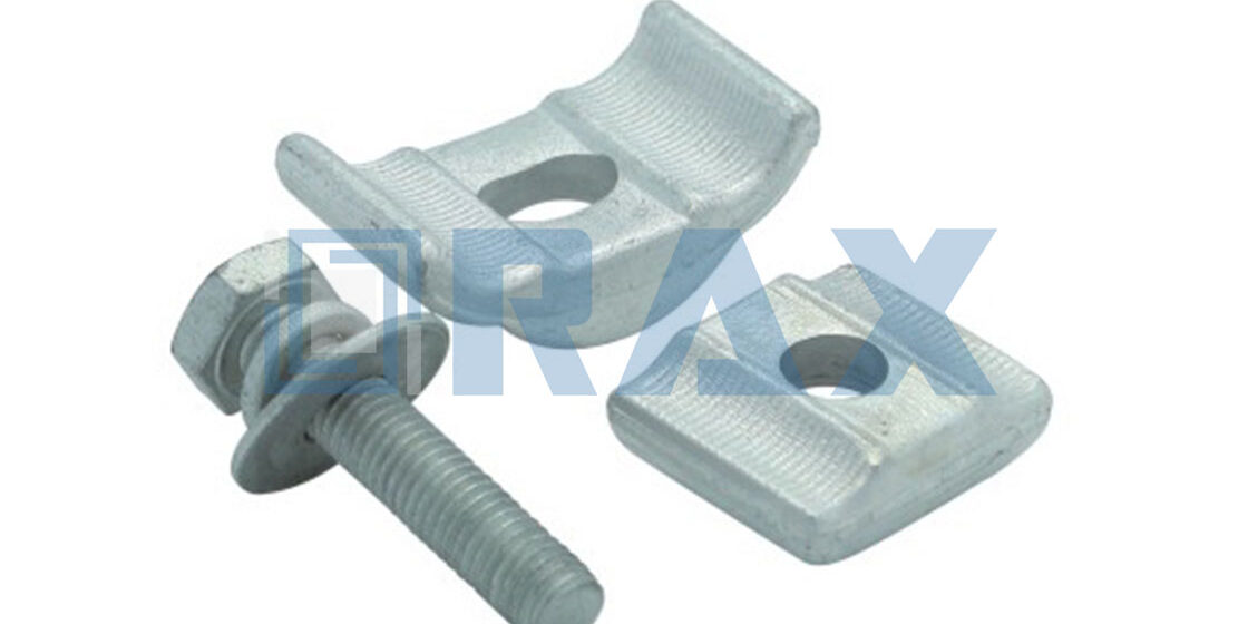
Engineers often treat the choice between a parallel groove clamp and compression lugs as a simple vendor preference, but that assumption causes failures. A single improperly torqued bolt in a mechanical connector creates micro-arcing that corrodes the joint from the inside out within months. This risk is why technical specification engineers must understand the exact physical differences between these two connection methods.
We analyze contact resistance metrics, mechanical clamping force requirements, and thermal cycling performance to separate code-compliant hardware from cheap imports. The data reveals specific installation speed advantages for mechanical connectors alongside the superior long-term reliability of permanent compression joints.
The data reveals specific installation deficiencies that undermine long-term reliability. These findings are critical because the physical interface between conductors is the primary point of failure.
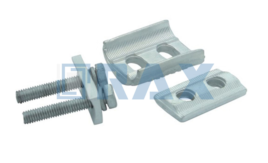
Comparing Technical Specs: Clamps vs. Lugs
Contact Resistance and Voltage Drop Metrics
In high-voltage infrastructure, the physical interface between two conductors is the primary point of failure. Parallel groove clamps (PGCs) utilize a mechanical friction-based interface to establish continuity. While effective for standard distribution taps, the contact resistance is highly dependent on the surface roughness of the conductor and the precision of the bolt torque applied.
Conversely, compression lugs rely on molecular cold-welding. The hydraulic pressure forces the metal of the lug and the stranded wire to flow into one another, creating a gas-tight, permanent alloy bond. This results in a significantly lower steady-state voltage drop compared to mechanical interfaces, which naturally possess microscopic air gaps even under high tension.
While this metallurgical bond creates a highly conductive path, the physical durability of the joint under extreme stress remains a separate critical concern. Evaluating how these connections behave during high-current fault events naturally leads to a comparison of mechanical holding forces.
This distinction in joining methodology sets the stage for understanding how different connection types respond to mechanical stress. Consequently, it is essential to evaluate the specific forces at play during fault conditions.
Mechanical Clamping Force Versus Crimp Integrity
The core engineering debate centers on how tensile strength is maintained during a fault event. A parallel groove clamp derives its holding power from the radial clamping force exerted by the bolts against the groove walls. If the installation team fails to achieve the precise Newton-meter (Nm) specification, the mechanical grip weakens rapidly under thermal expansion, leading to arc flashes.
Compression lugs, however, distribute the stress across the entire circumference of the barrel. When properly crimped using a hexagonal or oval die, the lug’s structural integrity becomes greater than that of the conductor itself. This means that in a catastrophic short-circuit scenario, the conductor will fail before the mechanical connection separates.
This mechanical robustness must be evaluated alongside the material’s response to environmental fluctuations. While compression ensures a secure physical connection, the long-term reliability of overhead lines depends heavily on how these connections withstand repeated thermal stress.
Thermal Cycling Performance and Expansion Rates
Overhead lines are subjected to daily and seasonal temperature swings, causing continuous expansion and contraction. This phenomenon, known as thermal cycling, is the silent killer of overhead connections. When the conductive metal expands, it pushes outward against the hardware; when it contracts, it pulls inward.
Mechanical grooves are susceptible to loosening over time due to these cyclic movements. The friction surfaces gradually “creep,” requiring scheduled maintenance re-torquing to maintain safety margins. In contrast, a properly compressed lug acts as a monolithic unit. Because the metal has been deformed plastically, it accommodates the thermal movement through the material’s inherent elasticity rather than shifting physical position.
Attempting to compensate for thermal cycling in mechanical clamps by over-torquing can strip the threads or crush the aluminum strands. Always adhere strictly to manufacturer torque charts to preserve the clamping force over the asset’s lifecycle.
| Feature | Specification | Advantage |
|---|---|---|
| Connection Method | Mechanical (Parallel Groove) vs. Compression (Crimp) | PG Clamps offer rapid installation; Compression provides superior, permanent high-current conductivity. |
| Material Composition | Aluminum/Steel Alloy or Bimetallic Copper-Aluminum | Prevents galvanic corrosion when joining dissimilar metals; ensures long-term structural integrity. |
| Corrosion Resistance | Hot-Dip Galvanized (ISO 1461), >85 Microns Coating | Delivers exceptional protection against harsh environmental elements and extreme weather conditions. |
| Quality & Testing | IEC 120 Load/Gauge Testing & SGS Verified | Guarantees strict dimensional accuracy and reliable performance under heavy electrical loads. |
| Compliance & Safety | NEC 250.70 Grounding/Bonding Standards | Ensures legal compliance for permanent connections, preventing inspection failures and safety risks. |
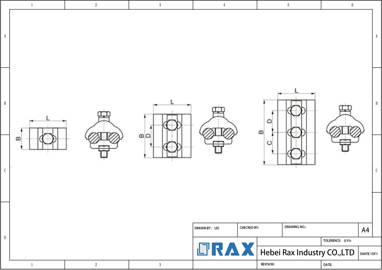
Speed and Labor: Mechanical vs. Hydraulic
Mechanical connectors offer superior speed for distribution taps and jumper connections, reducing labor hours by eliminating heavy hydraulic tooling setup and battery cycle management.
Installation Cycle Time Analysis
When evaluating labor efficiency on overhead line projects, the distinction between mechanical clamping and hydraulic compression is stark. Parallel groove clamps utilize a mechanical fastening system—typically bolts and nuts—that requires only standard hand tools (socket wrenches or torque wrenches). This allows for a rapid installation cycle often measured in seconds per connection once the conductor is positioned. In contrast, compression lugs demand a hydraulic process: the technician must position the lug, select the correct die, operate the pump (often 10-12 tons of force), wait for the full crimp cycle, and then retract the ram before repeating. This hydraulic cycle significantly slows down the workflow, particularly when dealing with multiple connections on a single pole or crossarm.
Tooling Logistics and Mobility
The labor impact extends beyond the moment of connection to the logistical burden of the equipment. Mechanical clamping systems are lightweight; a lineman’s pouch can carry all necessary hardware and tools up the pole without affecting mobility or safety. Hydraulic compression introduces substantial weight and complexity:
- Weight Penalty: Hydraulic pumps and heads can add 10–15 lbs (4.5–6.8 kg) to a lineman’s load, increasing fatigue and risk during climbs.
- Setup Time: Before crimping can begin, hoses must be connected, and safety checks performed on the hydraulic fluid reservoir and battery levels.
- Die Management: crews must haul a full set of crimping dies to accommodate various conductor sizes, whereas mechanical clamps often cover a broader range of conductor diameters with a single SKU or fewer variants.
Labor Efficiency Comparison
For bulk procurement managers and project planners, the choice of technology dictates the required crew size and project duration. The following table illustrates the fundamental divergence in labor application between these two methodologies:
| Efficiency Factor | Mechanical (PG Clamp) | Hydraulic (Compression Lug) |
|---|---|---|
| Tool Portability | High (Hand tools only) | Low (Heavy pump/head) |
| Setup per Connection | None (Immediate) | Required (Die selection + hose connection) |
| Crew Size | Single Lineman | Often requires Ground Support |
| Maintenance Dependency | Low (Tool cleaning only) | High (Hydraulic fluid, seals, battery charging) |
For large-scale maintenance projects involving hundreds of distribution taps, mechanical clamping can reduce total project man-hours by an estimated 30–40% simply by eliminating the hydraulic bottleneck. However, for permanent high-voltage splices where a gas-tight connection is non-negotiable, the labor trade-off for hydraulic compression is justified.
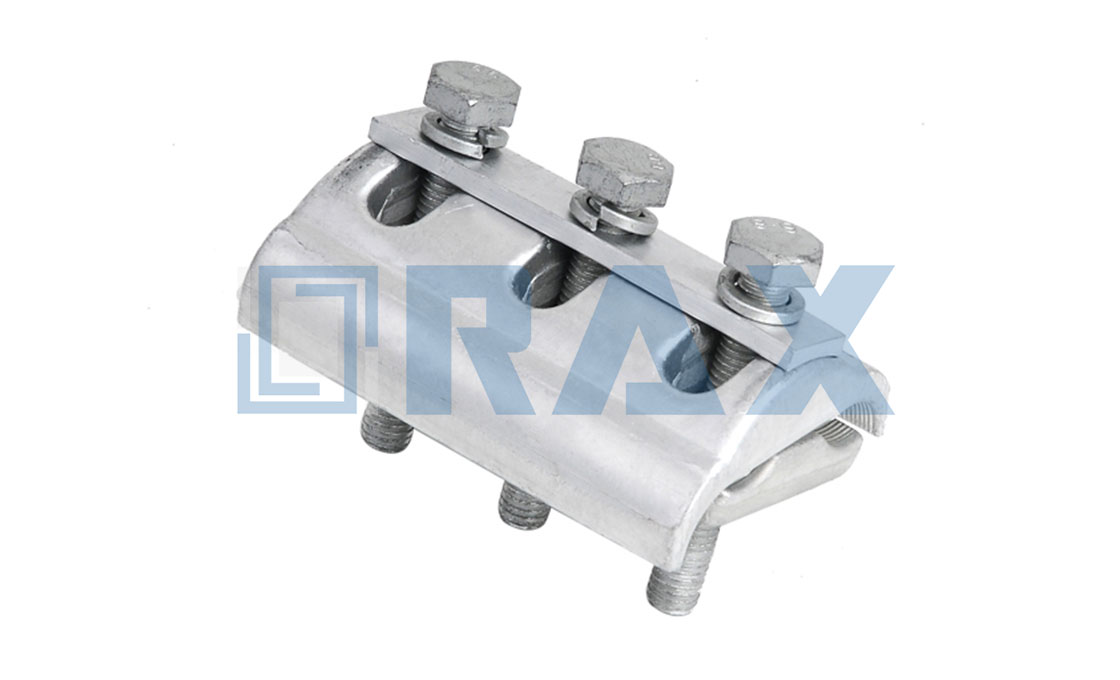
Long-Term Reliability and Maintenance Needs
Long-term reliability in overhead lines hinges on mechanical tension retention and corrosion resistance to prevent maintenance-induced outages.
For B2B utility buyers and grid operators, the true cost of hardware is not found in the initial unit price, but in the Total Cost of Ownership (TCO) over a 20-to-30-year asset lifecycle. Long-term reliability for pole line hardware—specifically mechanical connectors like Parallel Groove Clamps (PGCs) and compression lugs—is dictated by two primary factors: the retention of mechanical clamping force under thermal stress and the structural integrity of corrosion protection against environmental exposure.
Thermal Cycling and Mechanical Stability
Overhead conductors undergo significant physical expansion when heated by electrical load or ambient summer temperatures, and contraction during cooling or winter months. This continuous thermal cycling places immense shear and tensile stress on the connection points. If a connector cannot maintain its internal clamping force through these cycles, the connection impedance increases, leading to localized heating, accelerated degradation, and ultimately, catastrophic failure.
Mechanical PGCs rely heavily on the precision of their parallel grooves and the uniformity of the applied tension across the bolts. A high-quality mechanical connection must accommodate the differential expansion rates between the aluminum or copper conductor and the steel or aluminum housing without loosening. Conversely, compression lugs offer a permanent, gas-tight metallurgical bond that eliminates this loose connection risk entirely. However, the integrity of a compression joint is permanently reliant on the initial crimping accuracy; any void left during the hydraulic process becomes a long-term point of failure as thermal stresses build up.
- Tension Retention: Look for hardware rated to withstand thousands of thermal cycles without bolt relaxation.
- Material Compatibility: Ensure the connector material (e.g., Aluminum) matches the conductor to prevent galvanic corrosion, which rapidly destroys conductivity.
Corrosion Resistance and Environmental Exposure
Environmental degradation is the silent killer of pole line infrastructure. Hardware exposed to coastal salt spray, industrial pollution, or extreme humidity requires robust surface treatment to survive decades in the field. The standard baseline for heavy-duty outdoor hardware is hot-dip galvanizing, which provides a sacrificial zinc barrier protecting the underlying steel from rusting.
When evaluating long-term maintenance needs, the coating thickness and coverage are critical metrics. Thin electro-galvanized coatings fail quickly in harsh climates, requiring frequent replacement. High-specification hot-dip galvanizing ensures a thick, metallurgically bonded layer that can withstand physical handling damage during installation and years of environmental assault. For non-metallic components, UV-stabilized polymers must be used to prevent brittle cracking under direct sun exposure.
Impact on Asset Lifecycle Management
Reliable hardware directly correlates with lower operation and maintenance (O&M) expenditures. When purchasing for long-term grid stability, procurement teams must verify that all hardware meets rigorous international standards for fatigue testing and salt-spray resistance. Choosing hardware that lacks these verifiable long-term test data guarantees higher downtime risks and more frequent capital replacements down the road.

Meeting NEC and IEC Code Standards
North American projects mandate “Listed” hardware (UL/ETL), while international markets rely on performance-based testing (IEC 61238). Selecting the wrong regulatory approval for the target market is a primary cause of supply chain rejection.
For B2B buyers sourcing pole line hardware, understanding the divergence between the National Electrical Code (NEC) and International Electrotechnical Commission (IEC) standards is non-negotiable. While both frameworks aim to ensure grid safety, they approach certification from fundamentally different angles. The NEC acts as a prescriptive legal mandate in North America, strictly requiring “Listed” devices for grounding and bonding. In contrast, IEC standards focus on defining the test methods and performance criteria that the hardware must physically achieve during operation.
NEC 250.70 and the “Listed” Requirement
In the context of overhead line grounding, NEC Article 250.70 serves as the critical gatekeeper. The code explicitly states that the connection of grounding electrode conductors to grounding electrodes must be made by specific listed means, including listed pressure connectors, listed clamps, or other listed fittings. For Parallel Groove Clamps (PGC) and Compression Lugs intended for the US market, simple “compliance” with technical specs is insufficient; the product must carry a certification mark from a Nationally Recognized Testing Laboratory (NRTL) such as UL or Intertek, verifying compliance with standards like UL 467 or UL 486B.
This imposes a specific burden on procurement. If a compression lug lacks a proper UL listing stamp, it is technically illegal to install in a NEC-governed jurisdiction, regardless of its engineering quality. Buyers must verify that the manufacturer has undergone the specific listing process for the exact conductor sizes and materials being used (e.g., copper to copper vs. copper to aluminum).
IEC 61238: The Performance-Based Standard
For markets operating under IEC protocols (Europe, Southeast Asia, parts of South America), the focus shifts to IEC 61238-1 (“Low-voltage connection devices for conductors – Requirements and tests”). Instead of relying solely on a “Listed” label, IEC standards demand that connectors pass rigorous physical testing sequences to verify their suitability. This includes a four-step test sequence: Mechanical preparation, initial electrical resistance testing, current cycling (thermal) testing, and short-circuit testing.
- Thermal Cycle Stability: The connector must maintain stable electrical resistance through repeated heating and cooling cycles without loosening.
- Pull-Out Strength: Must withstand specified mechanical loads to ensure the conductor does not slip under tension.
- Corrosion Resistance: Must operate correctly in defined corrosive atmospheres, typically validated by Salt Spray tests (ASTM B117 or equivalent).
Under IEC standards, Parallel Groove Clamps are often evaluated for their ability to be re-torqued, whereas Compression Lugs are evaluated for the permanence of their crimp. B2B buyers must request “Type Test Certificates” to prove the specific batch or model has passed these IEC 61238 benchmarks.
Installation Compliance: Torque vs. Compression
Meeting the code is not just about the hardware itself; it is about the installation method prescribed by that code. A significant pain point in field compliance involves the tools used to install the hardware.
- Parallel Groove Clamps: Under both NEC and IEC, these devices generally require installation to a specific torque value. Overtorquing can distort the body and break the galvanizing seal, while undertorquing leads to high contact resistance and overheating. Code-compliant installation requires calibrated torque wrenches, not standard socket sets.
- Compression Lugs: NEC compliance is heavily dependent on using the correct die and tool for the specific lug. Using a non-matching die, even if it crimps the connector, technically violates the manufacturer’s listing and thus the NEC.
Material and Galvanization Standards
Regardless of the regulatory framework, the underlying materials must meet specific physical durability standards to be code-compliant. For steel components (bolts, clamps, brackets), Hot-Dip Galvanizing is the standard defense against corrosion.
In IEC and many international specifications, the galvanization process is typically measured against ISO 1461, which specifies the minimum zinc coating mass. For heavy-duty industrial environments, Class C coatings (referencing ASTM A153) or equivalent ISO thicknesses are often mandated. Buyers should verify that the mechanical strength of the hardware—such as Grade 8.8 steel for high-stress bolts or A2-70/A4-80 for stainless steel variants—matches the load requirements defined in the project’s structural codes, which run parallel to the electrical codes.
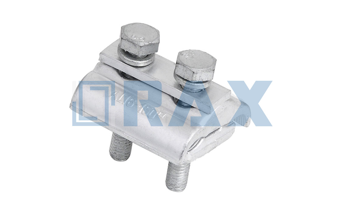
Choosing Between Budget and Speed
Unit Cost Analysis for Bulk Procurement
When evaluating procurement budgets, general contractors often fall into the trap of comparing unit prices in isolation. A parallel groove clamp typically commands a higher initial material cost compared to a standard compression lug. However, this comparison ignores the hidden capital expenditures associated with mechanical alternatives—specifically, the necessity of hydraulic power packs and specialized dies.
- Mechanical Clamps: Require only standard wrenches and U-bolts, eliminating tool depreciation and battery rental fees.
- Compression Lugs: Demand significant investment in hydraulic compressors, die sets, and ongoing maintenance.
For large-scale utility projects, the cumulative savings from avoiding heavy machinery rentals often offset the per-unit price difference. additionally, Rax Power utilizes automated hot-forging processes and strict ISO 1461-compliant galvanizing (exceeding 85 microns) to ensure that our mechanical clamps deliver structural integrity without the premium pricing of bespoke castings.
Installation Labor Time and Tooling Requirements
In high-density overhead line work, speed is directly correlated to labor costs and worker fatigue. Parallel groove clamps offer a distinct logistical advantage: they are “tool-light” and require minimal training to install correctly. A technician can secure a connection in seconds using basic hand tools, whereas compression lugs demand precise alignment, die selection, and multi-step hydraulic crimping.
Our engineering team has observed that relying on mechanical connections significantly reduces the physical burden on field crews. By removing the dependency on bulky hydraulic equipment, we enable teams to maintain a rapid pace, particularly in confined spaces or remote locations where transporting heavy machinery is logistically impractical. This efficiency allows for faster project turnover and reduced on-site downtime.
Total Cost of Ownership Over Asset Lifecycle
The true measure of procurement value lies in the Total Cost of Ownership (TCO) across the entire asset lifecycle. While compression lugs are historically viewed as permanent, they are susceptible to cold-flow issues if not torqued perfectly, potentially requiring re-crimping or replacement during maintenance cycles.
Parallel groove clamps provide a Strong alternative that balances immediate installation speed with long-term reliability. The use of forged steel and advanced alloy materials ensures resistance to thermal cycling and extreme environmental stress. By integrating rigorous double-review QC protocols and standardized IEC 120 load testing, our hardware minimizes the risk of catastrophic failure, reducing costly emergency repairs and ensuring sustained grid performance over decades of operation.
| Criterion | Parallel Groove Clamp (Mechanical) | Compression Lug (Hydraulic) | Rax Power Advantage |
|---|---|---|---|
| Installation Cost & Tooling | Low investment; requires only standard tools (wrenches) for bolted assembly (Iron 8.8) | High initial cost; requires specific hydraulic compression tools and dies | Offers OEM/ODM custom mold development to optimize design for cost-efficiency and tool-light installation |
| Conductivity & Performance | Tooth-type groove design ensures small contact resistance and reliable connection; Siamesed parts prevent loss | Provides gas-tight connection via cold-welding; superior for high-current and permanent grounding | Rigorous in-house load and gauge testing per IEC 120 standards; 100% double-review QC protocol |
| Material & Durability | Constructed from Forged Steel and Aluminum Alloy; enhanced with Hot-dip Galvanizing | Typically seamless Copper or Aluminum; often plated for corrosion resistance | ISO 1461 compliant Hot-Dip Galvanizing with mean coating thickness exceeding 85 microns |
| Application Scenario | Ideal for overhead power distribution and station accessories; used with insulating covers for protection | Best for high-voltage transmission lines and NEC 250.70 compliant grounding where permanence is critical | Market-specific solutions for extreme environments (Russia, South America) and local tender specifications |
Conclusion
To ensure these specifications are met with the highest level of precision, we provide comprehensive engineering validation. Our process involves detailed analysis to guarantee reliability in your specific operating environment.
Send us your conductor types and tower geometry. Our engineers perform in-house thermal cycling and mechanical pull tests to validate every connection point before you buy. We ensure the fit meets NEC standards immediately. Send over your project specs for a technical review and we’ll help you finalize the bill of materials.
Frequently Asked Questions
What is the difference between parallel groove clamps and compression lugs?
Parallel groove clamps are mechanical connectors that clamp onto the conductor without removing insulation, allowing for quick installation and adjustments. Compression lugs require stripping the conductor insulation and using a hydraulic or manual press to deform the lug around the wire, creating a permanent, high-integrity metallurgical bond.
Which connector is best for overhead lines?
Parallel groove clamps are widely used in overhead line applications for their ease of installation and ability to accommodate minor conductor misalignments. They are particularly popular in guy wire and secondary line connections where adjustability is key. Compression lugs are preferred for permanent terminations on poles or in substations where maximum reliability and weather sealing are paramount.
How do these connectors handle galvanic corrosion between copper and aluminum?
Connecting copper and aluminum directly creates galvanic corrosion risks due to their different electrochemical potentials. Parallel groove clamps often use bimetallic plates or special coatings to mitigate this, but insulation is still recommended. Compression lugs should be tin-plated or coated to prevent oxidation and ensure a stable, low-resistance interface between dissimilar metals.
How can conductor damage be prevented during installation?
Improperly tightened groove clamps can nick or crush strands, especially with soft aluminum conductors. Compression lugs, when crimped correctly with the right die, distribute pressure evenly and preserve conductor integrity. At Raxpower, we recommend using calibrated tools and following manufacturer torque specifications to minimize any risk of mechanical damage during installation.
When should I choose a compression lug over a parallel groove clamp?
Choose compression lugs when you need a permanent, low-resistance connection that will not loosen over time, such as in main service entrances, transformer terminations, or underground vaults. They offer superior vibration resistance and environmental sealing compared to mechanical clamps, making them ideal for critical infrastructure where maintenance access is limited.