
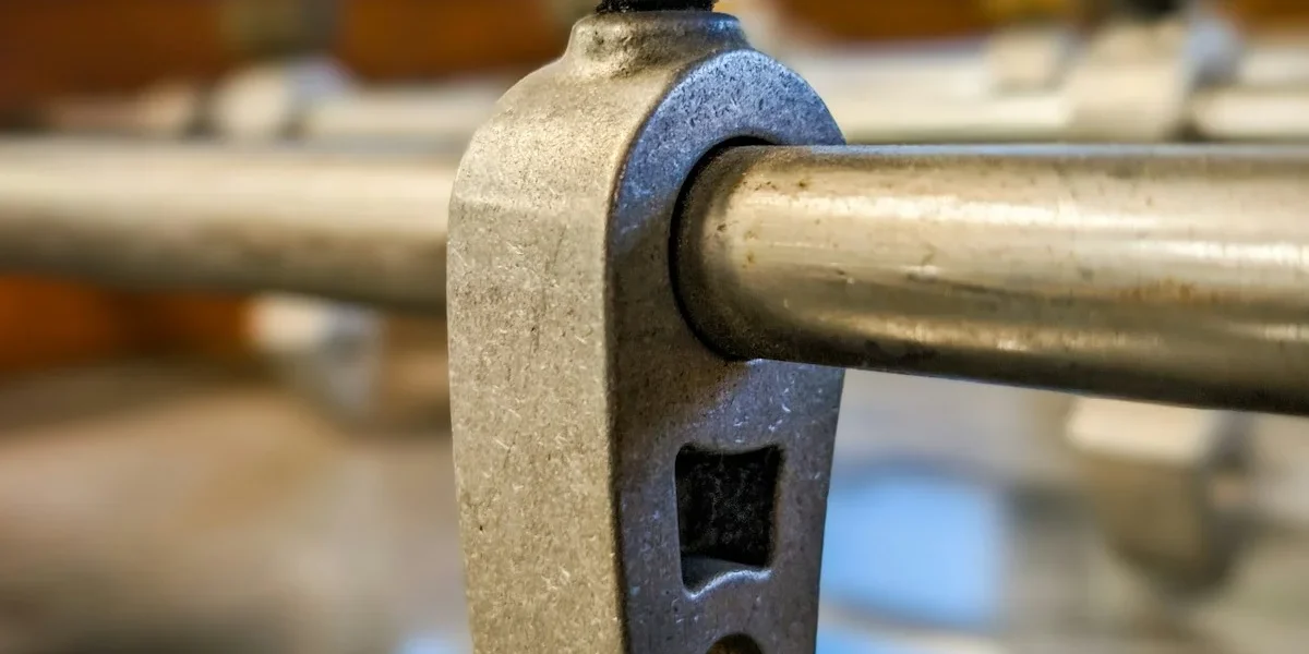
What happens when a suspension clamp transfers full line tension into a compromised conductor? If your Armor Rod spec only checks diameter and material, you are already underwriting a fatigue failure. Most procurement files treat these helical wraps as passive wear guards. They are not. A correctly engineered rod absorbs clamp-induced bending, redistributes point loads, and must restore at least 95 percent of the parent conductor’s minimum breaking strength before it earns a place on the bill of materials.
That 95 percent threshold comes straight from the static tensile testing protocols our production facility runs on every batch. We are walking through the actual test sequences behind those ratings, how alloy chemistry and rod diameter set the hard ceiling for load capacity, why winding pitch changes everything, and where IEC 61238 compliance actually meets field reality. You will also see how to match calculated mechanical loads to the right sleeve length without over-specifying or starving the connection.
By the end of this breakdown, you can audit vendor test reports with confidence, stop paying for oversized inventory that never improves grid life, and specify hardware that survives wind-induced oscillation long after the initial energization passes inspection.
Testing Methods Behind Tensile Strength Ratings
Tensile strength ratings are empirically derived through destructive static loading and dynamic fatigue simulations, validated by strict dimensional gauge checks to ensure consistent field performance.
Static Tensile Load Testing Procedures
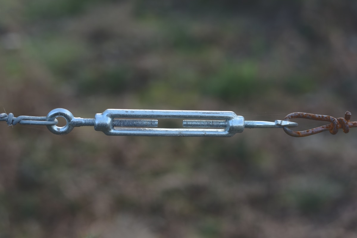
Static tensile testing is the benchmark for determining the Ultimate Tensile Strength (UTS) and Rated Breaking Load (RBL) of pole line hardware. During this process, a sample assembly—such as an anchor rod or suspension clamp—is subjected to a continuously increasing uniaxial tension force using a calibrated hydraulic or servo-electric testing machine. The load is applied at a steady rate until the assembly experiences mechanical failure, fracture, or slippage beyond a specified threshold. This test verifies that the hardware can withstand the short-term, high-stress forces expected during extreme weather events or construction tensions.
In our manufacturing protocol, we conduct these destructive tests on every production batch. We test to ensure that the actual breaking load meets or exceeds the theoretical design values, accounting for the variances often found in hot-forged steel compared to standard castings. By correlating the laboratory breaking load with the yield strength of the base material, we establish a safe Working Load Limit (WLL) that includes the necessary safety factors required by utility engineers.
Cyclic Vibration Fatigue Evaluation Methods
While static testing defines absolute strength, cyclic vibration fatigue evaluation assesses long-term durability under dynamic conditions. Overhead lines are constantly subjected to aeolian vibration and wind-induced galloping, which can cause metal fatigue at stress concentration points long before the static load limit is reached. To evaluate this, hardware is subjected to repetitive loading cycles—often millions of iterations—at varying amplitudes and frequencies. This simulation identifies potential weaknesses in the assembly, such as stress cracking in anchor eyes or loosening of preformed helical rods.
Our fatigue testing protocols are designed to replicate the harsh environments our clients face in markets like Russia and South America. We specifically monitor how the hardware maintains grip pressure and structural integrity over extended periods. This method ensures that the tensile rating advertised today remains valid throughout the asset’s lifespan, preventing premature failures caused by vibration fatigue that a standard static pull test would miss.
In-House Gauge Verification Against IEC 120
Dimensional accuracy is a prerequisite for achieving rated tensile strength; if a component does not fit the mating hardware perfectly, stress distribution becomes uneven, leading to premature failure. In-house gauge verification involves the use of “Go/No-Go” gauges and precise measurement tools to ensure every geometric parameter falls within the strict tolerances defined by IEC 120. This standard is critical for verifying the interface compatibility of bolts, nuts, and pole hardware, ensuring that the friction and contact areas necessary for load transfer are optimized.
We strictly enforce this standard in our quality control workflow. Our dedicated 10-person QC team utilizes IEC 120 compliant gauges to inspect critical dimensions on 100% of our products before packaging. By catching dimensional deviations immediately, we prevent the assembly of hardware that could compromise the structural integrity of the transmission line. This double-review process guarantees that the tensile strength ratings on the data sheet are physically achievable in the field, not just theoretical numbers based on ideal conditions.
How Base Metal Chemistry Sets Strength Limits
Base metal chemistry acts as the “genetic code” of hardware, defining the absolute theoretical limit for tensile strength and ductility before any manufacturing process begins.
The Atomic Foundation of Mechanical Capacity
The mechanical performance of pole line hardware is not solely determined by geometry or forging techniques; it is fundamentally dictated by the alloy composition. In metallurgical terms, strength is a function of how atoms are arranged and how difficult it is for dislocations to move through the crystal lattice when stress is applied. The specific ratio of alloying elements—such as Carbon in steel or Magnesium and Silicon in aluminum—creates these microscopic barriers. If the base chemistry lacks the necessary density of interstitial atoms or precipitates, no amount of work-hardening can compensate; the material will yield or fracture under load. For B2B buyers, this means that a Mill Test Report (MTR) verifying chemical composition is more critical than a load test sheet, as it proves the material has the intrinsic capacity to hold weight.
Aluminum Alloys: The Mg-Si Synergy in Preformed Products
For preformed line products like armor rods and grips, the base metal is typically an Aluminum-Magnesium-Silicon (Al-Mg-Si) alloy. The balance between Magnesium (Mg) and Silicon (Si) is critical because these elements combine to form Magnesium Silicide (Mg2Si) precipitates during heat treatment. These precipitates are the primary mechanism for increasing strength.
- Magnesium Content: Higher magnesium levels generally increase tensile strength but can reduce corrosion resistance if not balanced correctly.
- Silicon Control: Silicon must be present in sufficient quantity to bind with magnesium. Excess free silicon can make the material brittle.
- Iron Impurities: Iron (Fe) is a common impurity in aluminum alloys. Strict control of Iron content is mandatory; high Fe forms brittle intermetallic compounds that can cause micro-cracking during the installation of helical rods, compromising the grip’s fatigue life.
Carbon Steel: Balancing Yield and Ductility
In steel hardware such as anchor rods, U-bolts, and cross arms, Carbon (C) is the dominant element setting strength limits. However, the relationship is non-linear and involves significant trade-offs.
- Low Carbon (0.15% – 0.25%): Typically used in earth anchors and anchors requiring significant bending or deformation during installation. The lower carbon content ensures high ductility, preventing the steel from snapping when twisted into dense soil. The trade-off is a lower yield strength.
- Medium Carbon (0.30% – 0.50%): Found in high-load suspension hardware and cross arms. This chemistry provides a higher yield strength, essential for supporting static heavy loads, but requires precise heat treatment to avoid brittleness.
- Manganese and Phosphorus: Manganese is added to increase hardenability and tensile strength, while Phosphorus must be kept strictly below 0.04% to prevent cold shortness (brittleness in cold environments), a crucial factor for hardware exported to high-latitude markets.
The Silicon-Galvanizing Interaction
Chemistry also dictates the quality of the corrosion protection layer. The reaction between molten zinc and the steel substrate during hot-dip galvanizing is heavily influenced by the Silicon content of the base steel.
Steels with Silicon content in the “Sandelin range” (approximately 0.03% to 0.12%) experience extremely rapid growth of the Iron-Zinc alloy layer. While this can result in a thick coating, it is often brittle and prone to flaking. High-quality pole line hardware requires steel chemistry controlled to avoid this reactive range, ensuring a smooth, ductile, and adherent galvanized finish that meets ISO 1461 standards without compromising the underlying fatigue strength of the forged component.
How Rod Diameter Drives Load-Bearing Strength
Rod diameter dictates load-bearing capacity not linearly, but exponentially through its influence on section modulus and resistance to buckling forces.
The Exponential Mechanics of Section Modulus
In the field of anchoring and pole line hardware, a common misconception is that increasing rod diameter provides a linear increase in strength. In reality, the relationship is governed by the geometry of the cross-section. For a rod acting as a column or a beam, the moment of inertia—and thus the stiffness—increases proportionally to the fourth power of the radius. This means a marginal increase in diameter yields a disproportionately massive gain in resistance to bending and deflection.
For B2B buyers, this physics lesson translates directly to ROI: specifying a rod with a slightly larger diameter can prevent catastrophic bending failures in lateral load applications without necessitating a complete redesign of the anchoring system. It is the most efficient variable to adjust when engineering for high-tension guy wires or aggressive soil conditions where lateral movement is a risk.
Shaft Configuration: Round vs. Square Helical Systems
While diameter is the primary driver of raw tensile strength, the shaft configuration determines how effectively that strength is transferred during installation and service. The industry standard generally splits into helical round shafts and square shafts, each leveraging diameter differently to achieve torque transfer.
- Square Shafts: These configurations utilize the corners of the shaft to engage the soil aggressively. This allows the rod to translate installation torque into high holding capacity more efficiently in rocky or dense stratums. The effective diameter here includes the diagonal width, which provides superior purchase against turning resistance.
- Round Shafts: Often preferred for deep penetration in softer soils, round shafts minimize soil displacement during installation. However, their load-bearing reliance is heavily dependent on the shaft diameter maintaining a perfect circle to ensure consistent bearing pressure along the length of the anchor.
Dimensional Consistency vs. Nominal Size
A specified diameter is only as good as the tolerance control maintained during production. A nominal 25mm rod that varies by even a fraction of a millimeter along its length creates weak points that become failure zones under stress. In utility applications, where dynamic loads from wind or ice are constant, this variance is unacceptable.
High-specification manufacturing utilizes hot-forging techniques not just for grain structure, but to ensure that the diameter remains consistent from the tip to the threads. When a rod is drawn or formed poorly, diameter necking occurs. A buyer must verify that the supplier adheres to strict dimensional tolerances, effectively guaranteeing that the “rated” diameter is the *actual* minimum diameter at every point along the shaft.
| Rod Attribute | Specification | Load-Bearing Mechanism | Engineering Advantage |
|---|---|---|---|
| Shaft Configuration & Diameter | Helical Cross-Section (Round/Square) | Torque Transfer Optimization | Delivers working torque up to 2,300 ft-lbs with reliable anchoring in rocky strata. |
| Material Forming Process | Hot-Forged Grain Structure | Tensile Strength Enhancement | Ensures superior structural integrity and deformation resistance versus cast alternatives. |
| Surface Coating Thickness | Hot-Dip Galvanizing (>85 µm / ISO 1461 & ASTM A123) | Corrosion Degradation Mitigation | Preserves rated load capacity throughout asset lifespan by preventing material loss. |
| Quality Control Protocol | Double Inspection & In-House Load Testing (IEC 120) | Breaking Load Verification | Guarantees compliance with global utility breaking-load standards via rigorous verification. |
Winding Angle and Pitch Directly Impact Strength
Helical geometry governs load transfer. Winding angle and pitch spacing must balance grip efficiency, radial pressure, and conductor protection.
The Mechanics of Helical Geometry
Preformed armor rods function as a semi-rigid helix that wraps around stranded conductors. Unlike bolted clamps, they rely on continuous mechanical interlock rather than point compression. The geometric relationship between wire lay angle and turn spacing determines how tensile forces distribute across the cable surface.
When a conductor experiences axial tension, thermal expansion, or wind-induced oscillation, the helix must convert those linear forces into uniform radial pressure. Poorly calibrated geometry creates stress concentrations that accelerate strand fatigue or allow gradual slippage under cyclic loading.
Winding Angle: Load Transfer vs. Flexibility
The winding angle defines the orientation of individual wire turns relative to the conductor axis. A steeper angle improves direct axial load transfer but increases overall stiffness. A shallower angle allows better contour conformity and easier installation around bends, but may reduce grip efficiency when dynamic tension spikes.
- High-angle configurations: Optimal for straight-run applications where maximum tensile retention is required. Increases resistance to pull-out but reduces conformability.
- Low-angle configurations: Preferred in complex routing or vibration-heavy spans. Improves flexibility but requires tighter pitch to compensate for reduced directional grip.
- Balanced geometry: Designed to maintain sufficient hold strength while preserving the conductor’s natural bending radius during installation and thermal cycling.
Pitch Spacing: Friction and Contact Area
Pitch refers to the distance between adjacent wire turns. It directly controls the contact surface area pressing against the cable. Smaller pitch values create denser wrapping, which raises friction and improves holding power under static and dynamic loads.
However, excessive pitch density introduces risk. Over-compressed turns can embed into soft aluminum strands, causing permanent deformation or micro-cracking. Conversely, widely spaced turns reduce contact area, allowing conductor movement that leads to fretting corrosion and accelerated wear.
- Dense pitch: Maximizes grip and load sharing. Suitable for high-tension dead-end zones and vibration-prone spans.
- Standard pitch: Provides balanced performance for general-purpose reinforcement and splice protection.
- Open pitch: Used where minimal radial pressure is required, typically in low-stress suspension or light-duty applications.
Combined Effect on Structural Rigidity
Angle and pitch do not operate independently. Together, they set the effective spring rate of the armor assembly. A tightly wound, steep-angle configuration behaves like a rigid sleeve, limiting conductor flex. A loosely wound, shallow-angle design acts more like a flexible band, allowing greater movement but reducing peak hold strength.
Engineers select geometry based on the expected mechanical environment. Transmission lines subject to galloping, ice shedding, or heavy conductor tension require optimized helical parameters that prevent slippage without restricting natural thermal movement.
Specifying pitch and angle based solely on product availability rather than calculated load transfer requirements leads to premature field failures. Undersized geometry slips under thermal cycling; oversized geometry damages strands through excessive radial pressure.
Match helical density to conductor strand hardness. Softer aluminum alloys require optimized pitch to prevent embedding, while high-strength composite or steel-reinforced conductors can tolerate denser wrapping without surface damage.

Manufacturing Changes That Harden the Rod
Mechanical hardening in line hardware depends on controlled plastic deformation, precise thermal management, and corrosion coatings that preserve the strengthened grain structure.
Work Hardening and Grain Structure Alignment
Preformed line hardware derives its primary strength from deliberate cold working during formation. As the steel substrate is mechanically shaped, dislocation density rises inside the crystal lattice, pushing the yield threshold higher without changing the base alloy composition. This process aligns the internal grain flow along the component curve, which directly improves resistance to sudden shock tension and repeated dynamic loading.
When compared to traditional casting routes, hot-forging and cold-forming techniques maintain a continuous fiber pattern and eliminate internal voids. Porous cast microstructures tend to fracture unpredictably under line shock, whereas deformed grain structures distribute stress more evenly across the conductor interface. This microstructural continuity is why modern overhead line hardware prioritizes mechanical deformation over simple melt-and-mold production.
Thermal Management and Coating Interactions
Heat application introduces a direct trade-off between stress relief and strength retention. Post-forming thermal treatments can reduce residual internal stresses, but temperatures that cross the material recrystallization point trigger grain regeneration, effectively resetting yield strength back toward the annealed baseline. Production cycles must therefore be calibrated to preserve the work-hardened matrix while still meeting dimensional stability requirements.
Surface protection layers also interact with the hardened core. Hot-dip galvanizing compliant with ISO 1461 typically delivers a mean coating thickness exceeding 85 microns, producing a smooth, bright finish that blocks corrosive exposure without obscuring critical tolerances. Molten zinc immersion requires strict temperature and dwell-time controls to prevent hydrogen embrittlement or localized softening near high-stress zones.
Dimensional Control and Batch Verification
Automated and semi-automated forming equipment keeps structural tolerances tight, typically maintaining a strict 1mm variance for precision hardware. Consistent geometry ensures that the hardened microstructure performs uniformly across every unit, removing reliance on manual finishing that can introduce uneven stress concentrations. Dimensional consistency also guarantees proper grip pressure and load transfer when the component interfaces with stranded conductors.
Final output validation focuses on confirming that microstructural hardening translates into declared mechanical ratings. In-house load and gauge checks against IEC 120 protocols verify that forming and coating cycles have not degraded structural capacity. Independent SGS assessment documents compliance for export markets, while multi-stage quality inspections review each batch before release to ensure field-ready reliability.
Over-thermalizing components during galvanizing or stress-relief cycles can erase the mechanical benefits of work hardening. Visual finish quality does not guarantee that the strengthened grain structure survived the finishing process intact.
Procurement teams should request documented coating thickness, tolerance records, and independent test references alongside rated breaking loads. These manufacturing markers confirm that hardening was preserved through the full production cycle.

Stronger Rods Extend Cable Fatigue Life
Key Takeaway: Armor rods extend conductor service life by converting destructive point-loads into uniform stress and absorbing dynamic bending strain at critical suspension points.
Uniform Stress Distribution on Stranded Conductors
Overhead stranded conductors, particularly ACSR (Aluminum Conductor Steel Reinforced), are inherently susceptible to uneven load distribution at support hardware locations. When a suspension clamp bears directly on the cable, the static load concentrates intensely on the few strands contacting the hardware, leading to “static fatigue” and the initiation of micro-cracks. Preformed armor rods mitigate this by creating a larger, effective diameter at the support point. The helical structure ensures that the compressive force from the clamp is distributed evenly across a wider surface area of the outer strands. This eliminates the high-stress concentrations that cause outer layer wire breakage, ensuring the conductor maintains its mechanical integrity under sustained tensile loads.
Mitigating Wind-Induced Galloping and Dynamic Oscillation Damage
The most critical vulnerability in a transmission line is the “bending point” where the conductor exits the suspension clamp. Wind-induced aeolian vibration and galloping subject this specific zone to millions of alternating stress cycles. Without reinforcement, the repeated flexing causes fatigue fractures in the aluminum strands. Armor rods function as a localized reinforcement layer, effectively increasing the bending stiffness of the conductor at the clamp exit. This structural reinforcement reduces the dynamic bending amplitude and the associated strain transferred to the core material. By damping these oscillations, the rods prevent the propagation of fatigue cracks caused by the conductor “working” against the edge of the suspension hardware.
Grip Pressure Balance for Conductor Preservation
Achieving a secure grip that prevents conductor slip without deforming the cable is a delicate engineering challenge. Standard suspension clamps must exert significant pressure to hold the line, but direct application can crush the softer aluminum layers, reducing the conductor’s cross-sectional area and altering its electrical resistance. Armor rods serve as a protective interface layer, absorbing the radial pressure of the clamp. Because the rods are preformed to match the conductor’s diameter, they ensure that grip pressure is applied uniformly rather than at localized high-impact points. This balance preserves the circular geometry of the conductor, preventing “notching” or deformation that would otherwise create weak points in the transmission infrastructure.
Which Industry Standards Validate Rod Strength?
Rod strength validation rests on international mechanical benchmarks, independent third-party audits, and region-specific utility mandates that collectively guarantee grid reliability.
When evaluating pole line hardware and transmission fittings, mechanical specifications alone do not guarantee field readiness. Utility procurement teams require a layered compliance framework that proves components survive operational stress, pass independent audit trails, and meet localized grid codes. The following standards define how mechanical performance is validated before hardware ever reaches a project site.
IEC 61238 Mechanical Performance Requirements
IEC 61238 establishes the baseline mechanical performance criteria for electrical connectors and associated overhead line accessories. Rather than treating mechanical testing as a final quality gate, this standard requires durability validation across multiple stress vectors. The framework ensures that fittings maintain structural integrity under combined tension, compression, and thermal cycling conditions typical of long-span transmission routes.
For preformed line products and heavy-duty anchors, compliance with IEC 61238 means the component cannot rely on nominal strength ratings alone. Procurement managers should verify that mechanical claims are backed by standardized performance envelopes rather than isolated peak-load figures. In our experience, aligning production tolerances to this framework eliminates premature fatigue failures in high-wind corridors where dynamic loading fluctuates continuously.
- Structural Integrity Verification: Confirms that fittings retain dimensional stability under sustained operational loads without permanent deformation.
- Thermal-Mechanical Cycling: Validates performance continuity across temperature extremes, preventing brittle failure during seasonal shifts.
- Interface Compatibility: Ensures mechanical coupling surfaces remain secure when mated with standardized conductor and hardware geometries.
SGS Third-Party Certification for Export Markets
Cross-border utility tenders almost universally require independent verification from recognized metrology and inspection bodies. SGS certification serves as a globally recognized audit trail that confirms manufacturing processes, material traceability, and final product conformity against declared specifications. For B2B buyers managing international supply chains, this external validation removes ambiguity around supplier claims and reduces procurement liability.
Third-party certification does more than stamp a final report. It validates that factory controls consistently reproduce certified results across production batches. When sourcing hardware for multi-year grid expansion projects, consistent manufacturing quality matters more than a single prototype success. Our internal review protocols are structured so that exported consignments carry full documentation chains, making customs clearance and utility acceptance inspections straightforward.
- Manufacturing Process Audit: Confirms that production methods match declared engineering controls and quality management systems.
- Material Traceability: Verifies that incoming metals and coatings correspond to specified grades and certifications.
- Batch-to-Batch Consistency: Demonstrates that every shipment maintains uniform performance characteristics without drift.
Regional Utility Compliance for Extreme Environments
Global power grids operate under wildly different environmental and operational demands. A hardware solution designed for temperate maritime climates often fails under Arctic conditions, while components sized for dense urban distribution may lack the safety margins required for remote mountain routes. Regional utility compliance addresses this gap by mandating localized testing, enhanced corrosion protection, and adjusted mechanical safety factors.
Different markets enforce distinct tender requirements based on their national grid codes. In extreme cold regions, procurement specifications prioritize high-breaking load capacity and impact resistance to survive ice loading and thermal contraction. Tropical and coastal utilities demand accelerated corrosion testing and tighter dimensional tolerances to withstand humidity, salinity, and rapid vegetation growth. Southeast Asian tenders frequently reference local manufacturing standards alongside international benchmarks, requiring suppliers to demonstrate both technical capability and local regulatory familiarity.
Do not assume a single mechanical rating satisfies all regional tenders. Always map the target utility’s environmental classification against the supplier’s certified compliance history before locking in procurement specifications.
We design our product configurations to match these regional realities rather than forcing a universal specification onto diverse grid architectures. When working with clients in high-stress environments, we calibrate dimensional tolerances, coating specifications, and mechanical safety margins to meet their specific utility mandates. This market-aware approach ensures that exported hardware passes local acceptance testing without requiring costly retrofits or replacement claims after installation.
| Technical Focus | Validating Standard | Test Requirement | Strength Implication |
|---|---|---|---|
| Corrosion Protection | ISO 1461 & ASTM A123 | Hot-dip galvanizing with a mean coating thickness exceeding 85 microns | Prevents material degradation and preserves tensile strength throughout the asset lifespan |
| Material Integrity | Hot-Forging Manufacturing Specification | Advanced hot-forging process optimizing grain structure over traditional casting | Delivers superior tensile strength and dimensional precision for high-torque installations |
| Quality Assurance | SGS Third-Party Certification | 100% double inspection by a dedicated 10-person QC team | Guarantees consistent manufacturing quality and compliance with international utility standards |
Matching Rod Size to Calculated Mechanical Loads
Selecting the correct armor rod requires aligning the rod’s helical diameter and tensile rating with the conductor’s Rated Tensile Strength and actual cross-section, while recognizing that rods restore strand integrity rather than carrying primary suspension tension.
Determining Maximum Allowable Working Load Limits
The maximum allowable working load (MAWL) of a preformed armor rod is defined by its capacity to restore damaged conductor strength, not by its standalone breaking load. A frequent procurement error is treating armor rods as functional equivalents to dead-end grips. This confusion leads to specification failures where the rod is expected to retain primary line tension, which is structurally incorrect.
Engineers calculate the required MAWL based on the conductor’s Rated Tensile Strength (RTS) and the extent of strand damage. Under IEC 61238 performance classes, a properly selected armor rod must recover the conductor’s tensile envelope to meet the utility’s restoration threshold. We verify these load ratings through rigorous in-house load testing and gauge testing per IEC 120, ensuring every rod meets the published mechanical claims before it leaves our facility.
Do not specify an armor rod to carry primary suspension tension. If the hardware stack requires primary load retention, specify a dead-end grip or tension clamp. Using an armor rod for primary tension creates a single-point failure risk and violates standard overhead line design principles.
Sizing Selection Based on Conductor Cross-Section
Rod diameter selection is dictated by the conductor’s outer diameter and strand configuration, not merely the nominal kcmil rating. Two conductors with identical cross-sectional areas can have different outer diameters due to variations in stranding pitch and compaction. Sizing the rod incorrectly introduces two failure modes: a loose fit allows the rod to slide under thermal cycling, while an overly tight fit crushes aluminum strands and initiates fretting corrosion.
- Conductor Outer Diameter: Match the rod’s internal helix diameter to the specific OD of the conductor, accounting for manufacturing tolerances in both the rod and the cable.
- Strand Configuration: ACSR, AAAC, and Alumoweld conductors present distinct surface profiles. The rod geometry must conform to the strand contour to maximize contact area and grip uniformity.
- Material Compatibility: Aluminum alloy rods are standard for aluminum-based conductors to prevent galvanic wear. Galvanized steel variants serve specific corrosion environments where mechanical hold is prioritized over conductivity recovery.
For projects involving non-standard or proprietary conductor profiles, off-the-shelf sizing becomes unreliable. Rax Power evaluates the conductor cross-section against our preformed line catalog to eliminate slip risks, and we maintain the capability to produce specialized sizes for complex installations.
Applying Safety Factors for Dynamic Tension Loads
Static load calculations rarely capture the full stress spectrum on overhead lines. Wind galloping, ice accretion, and short-circuit electrodynamic forces introduce dynamic tension spikes that can significantly exceed steady-state operating conditions. Utility codes mandate safety factors that vary by span length, terrain exposure, and climatic zone.
When specifying rods for dynamic environments, the safety factor must account for fatigue cycles at the clamp interface. Our engineering team integrates these dynamic parameters during selection, ensuring the rod’s grip pressure resists micro-movement without overstressing the conductor. This calibration is particularly critical for regions with extreme weather profiles. Rax Power supplies high-breaking load solutions validated by SGS testing, tailored for markets such as Russia where extreme environmental demands require elevated mechanical margins.
Dynamic span calculations require pairing with vibration damping strategies to ensure holistic system integrity. Raxpower manufactures spiral vibration dampers alongside preformed line products, allowing utilities to address both mechanical load distribution and fatigue mitigation from a single supply chain.
OEM Customization for Non-Standard Mechanical Demands
Standard catalogs cover the majority of global grid infrastructure, but specialized projects frequently demand deviations. Extreme voltage classes, oversized bundled conductors, or unique utility tender specifications can push hardware beyond standard dimensional envelopes. In these cases, generic sizing compromises reliability.
Transforming customer samples, drawings, or performance concepts into finished products relies on full OEM/ODM capabilities and custom mold development. Unlike suppliers relying solely on cast components, Raxpower leverages hot-forging technology to deliver superior grain structure and tensile integrity in custom geometries. Hot-forging provides measurable advantages in strength and precision compared to traditional casting, which matters most when projects require exceptional load-bearing performance.
To ensure long-term reliability in custom orders, surface protection standards must meet rigorous galvanizing requirements. All processes remain SGS tested and verified. Custom orders receive hot-dip galvanizing compliant with ISO 1461 and ASTM A123, delivering a smooth, bright finish with a mean coating thickness exceeding 85 microns for maximum corrosion resistance.
Strict utility standards in South America and localized tender requirements in Southeast Asia demand a customization pipeline that preserves compliance and durability. Raxpower meets every non-standard mechanical demand with precise dimensional accuracy, ensuring long-term performance under region-specific engineering loads.
Conclusion
Stronger armor rods do more than hold their shape. They spread strain across stranded conductors and stop wind-induced galloping from chewing through the wire. Select the tensile rating based on calculated working loads. Anything lower invites premature fatigue in the conductor itself. Our internal testing against IEC 120 and IEC 61238 confirms that base metal chemistry and winding pitch dictate whether a rod survives decades of vibration or fails mid-service.
- Verify rod diameter against conductor cross-section before committing to volume orders.
- Confirm SGS or regional utility certification exists for your target export markets.
- Treat our engineering team as technical backup for sizing calculations or IEC gauge verification, with zero obligation to purchase.
Frequently Asked Questions
Do armor rods carry primary tension?
No, armor rods are designed to protect conductors from vibration, abrasion, and stress concentrations rather than serve as primary load-bearing components. They reinforce the conductor against mechanical damage but must always be used in conjunction with appropriate support hardware. Mistaking them for tension-rated hardware like dead-end grips can compromise the safety and integrity of the line.
How to match armor rod materials?
The armor rod material must be chemically compatible with the conductor material to prevent galvanic corrosion, typically using aluminum alloys for aluminum conductors. Using dissimilar metals without proper protection can lead to accelerated wear and premature failure of the hardware. Engineers should always verify material compatibility charts against specific environmental conditions.
Can armor rods repair damaged conductors?
Armor rods can effectively restore the mechanical strength of conductors, provided the damage does not exceed approximately 25% of the total strand cross-sectional area. For damage beyond this threshold, the structural integrity is too compromised for safe repair, and conductor replacement is necessary. Adhering to these limits ensures the repaired section maintains adequate breaking load under operational conditions.
Do armor rods prevent corona discharge?
Yes, when manufactured with precise geometry and a smooth surface finish, armor rods help maintain a uniform electric field around the conductor to minimize corona discharge. This is critical for Extra High Voltage (EHV) applications to prevent radio interference and power loss. At Raxpower, we emphasize strict dimensional control to ensure hardware meets the demands of high-voltage environments.
Does galvanizing impact service life?
High-quality hot-dip galvanizing provides a robust sacrificial layer that protects the underlying steel from corrosion, significantly extending the hardware’s service life in harsh environments. Compliance with international coating standards ensures the finish withstands abrasion during installation and long-term exposure to the elements. Superior coating thickness is essential for maintaining the mechanical properties of the hardware.