
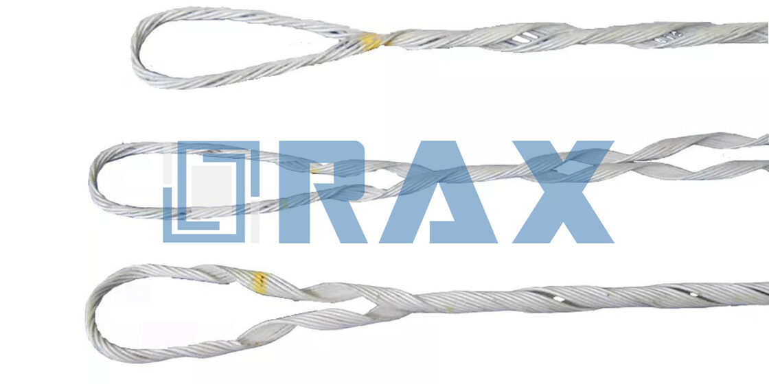
An anchor tension clamp is the critical load-bearing interface where overhead line tension transfers from conductor to structure, yet it remains one of the most frequently underspecified components in transmission and telecom projects. The real cost isn’t in the fitting itself but in what happens when grip strength falls short—conductor slip under ice loads, micro-bending damage on ADSS cables, or tower misalignment over decades of thermal cycling. For specification engineers managing uptime KPIs, understanding exactly how this hardware performs under dynamic stress isn’t optional; it’s your primary defense against warranty claims and field failures.
Consider that industry standards require anchor tension clamps to deliver ≥90% of conductor rated tensile strength (RTS) per IEC 61284, but hot-forged aluminum alloys consistently outperform cast alternatives by maintaining structural integrity through 500+ fatigue cycles at -40°C to +80°C temperature swings—a gap many generic suppliers gloss over in datasheets. This distinction matters particularly for dead-end applications where vibration and wind-induced oscillation compound mechanical stress on both the clamp body and conductor strands exiting the gripping zone.
This article examines how proper material selection—specifically comparing forged versus cast performance metrics—and precise installation techniques directly impact long-term reliability in overhead line systems. We’ll break down the load transfer mechanics behind effective grip design, explain why zinc coating thickness per ISO 1461 becomes decisive in corrosive environments, and detail the torque control methods that prevent premature strand separation without crushing the conductor beneath.
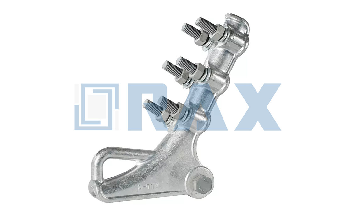
What Is an Anchor Tension Clamp?
An Anchor Tension Clamp is a termination fitting designed to secure the end of a conductor or optical cable, absorbing the full tensile load and transferring it to the support structure.
Core Function of a Tension Anchor Clamp
The fundamental job of an anchor tension clamp is to act as the end-point restraint for an overhead line. It is the component that “grabs” the conductor or optical cable—whether it is aluminum conductor steel reinforced (ACSR) or ADSS fiber optic cable—and holds it firmly against the mechanical tension generated by the span length and sag requirements. Unlike other hardware that merely supports the weight, the anchor clamp must withstand the full axial tension (the pulling force along the length of the cable) without allowing the line to slip or creep. In our manufacturing experience, this requires a precise balance of grip pressure and body strength to ensure the hardware itself does not deform under high load.
Distinction from Suspension Hardware Types
A common engineering error is confusing tension clamps with suspension hardware. While both attach to poles or towers, their physical functions are opposites. A suspension clamp acts as a dynamic hanger; it supports the vertical weight of the conductor but allows the cable to move longitudinally to accommodate thermal expansion and contraction, and it permits swinging in the wind. In contrast, a anchor tension clamp is a static lock. It fixes the conductor at a specific point, blocking longitudinal movement and absorbing the resultant mechanical stress. Using a suspension clamp in a termination point is a critical failure risk, as suspension clevises are not designed to handle the continuous, heavy axial loads that an anchor clamp manages daily.
- Load Direction: Suspension clamps primarily handle vertical gravity loads; Anchor clamps handle horizontal/axial tensile loads.
- Mobility: Suspension hardware allows for swing and slip; Anchor hardware creates a fixed, immobile termination point.
- Location: Suspension clamps are used at intermediate poles; Anchor clamps are used at dead-end poles, terminal poles, or heavy angle structures.
Role in Securing Overhead Conductors
The anchor clamp is the critical safety link preventing catastrophic line failure. Its role extends beyond simply “holding” the cable; it must distribute the gripping stress evenly to prevent damage to the conductor’s core. This is particularly vital for fiber optic cables like ADSS, where excessive localized pressure can cause micro-bending and signal loss. To guarantee long-term reliability, we design our clamps to maintain a slip load (grip strength) of at least 90-95% of the Rated Tensile Strength (RTS) of the cable. This means the clamp will hold the cable securely even under emergency load conditions, such as high wind or ice accumulation, ensuring the tension is transferred safely to the pole structure or insulator string rather than compromising the conductor itself.
- Grip Retention: Ensures the clamp does not slip under sustained loads over the cable’s 25+ year lifespan.
- Stress Distribution: Engineered components (like wedge inserts or preformed rods) spread clamping force to avoid crushing the cable layers.
- Vibration Dampening: In high-quality designs, the clamp system helps mitigate Aeolian vibration that could otherwise fatigue the conductor at the termination point.
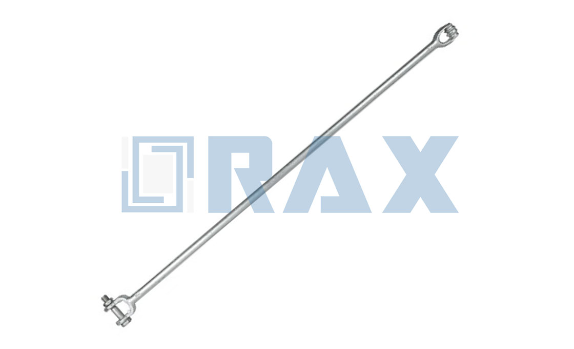
How Clamps Transfer Mechanical Loads
Mechanics of the Load Transfer Interface
The anchor tension clamp functions as the primary mechanical interface in an overhead line system, transferring tensile loads from flexible conductors to rigid support structures. When a conductor is secured within the clamp body, the load path flows directly through the compressive force exerted by the clamp jaws onto the cable strands. This creates a friction-based grip that must withstand continuous tension without slippage or permanent deformation.
Critical design considerations include the curvature radius of the clamp barrel and the contact surface profile. A properly designed clamp distributes stress evenly across the conductor cross-section rather than concentrating it at specific points. In our manufacturing process, we utilize hot-forged steel components which provide superior grain structure alignment compared to cast alternatives, ensuring more predictable stress distribution under load conditions.
Importance of Grip Strength vs. RTS
Grip strength represents the minimum tensile force a clamp can sustain before experiencing conductor slip, expressed as a percentage of the conductor’s Rated Tensile Strength (RTS). For reliable overhead line performance, industry standards typically require grip strengths of 90-95% of RTS. This threshold ensures that under maximum operational loads—including wind loading, ice accumulation, and thermal expansion—the conductor remains securely anchored without displacement.
At Rax Power, our quality control protocols include rigorous testing per IEC 120 specifications to verify grip strength performance. We maintain strict dimensional tolerances within ±1mm during production to ensure consistent jaw profiles that match specific conductor diameters. The precision we achieve in our hot-forging process directly correlates to reliable grip strength retention over the expected service life of the infrastructure.
Preventing Conductor Slip and Micro-bending
Conductor slip occurs when the applied tension exceeds the frictional resistance between the clamp and cable strands. This phenomenon can lead to progressive strand damage, reduced fatigue life, and potential failure at critical connection points. To prevent slip, manufacturers employ optimized jaw geometries with appropriate surface textures that maximize contact pressure while minimizing localized stress concentrations on individual strands.
Micro-bending represents another significant concern, particularly for fiber optic cables like ADSS and OPGW where even minor curvature can induce signal attenuation or complete breakage. Our preformed line products, including armor rods and dead-end grips, are engineered to distribute bending stresses along longer sections of the cable rather than concentrating them at discrete points. We incorporate these solutions into our comprehensive accessory offerings to address the specific requirements of both power transmission and telecommunications applications.

Key Benefits of Anchor Clamps
High-quality anchor clamps ensure grid reliability by maintaining a grip strength of at least 90% of the conductor’s Rated Tensile Strength (RTS) and resisting environmental fatigue through superior metal grain structure.
The primary value of an anchor clamp lies in its ability to transfer the immense mechanical tension of a conductor safely to the supporting structure without causing damage. For project engineers and procurement officers, the benefits of selecting a technically superior clamp extend far beyond simple fastening; they define the long-term maintenance costs and safety of the overhead line. A properly engineered clamp acts as a critical node in the infrastructure, effectively locking the conductor in place while distributing stress to prevent localized wear or failure over a 20-to-30-year service life.
Guaranteed Grip and Slip Prevention
The most critical performance metric for any anchor clamp is its grip efficiency. Industry standards mandate that a clamp must retain a minimum of 90% to 95% of the conductor’s Rated Tensile Strength (RTS) without slipping. This high retention rate is essential because if a clamp slips under load, it immediately invalidates all tower and foundation load calculations, leading to dangerous sagging and clearance violations. High-performance clamps achieve this through optimized helical or wedge designs that create a uniform pressure distribution along the conductor surface.
Never assume that a clamp labeled with the correct conductor diameter will automatically provide the required grip. Always verify the grip strength data against specific standards such as IEC 61284 or ASTM B232, and ensure installation torque specifications are strictly followed, as improper torque can reduce effective grip by up to 50%.
Superior Fatigue Resistance and Structural Integrity
Overhead lines are constantly subjected to dynamic forces such as wind-induced vibration, ice loading, and thermal expansion. Clamps manufactured using hot-forging techniques offer a significant reliability advantage over cast alternatives. The forging process aligns the metal’s grain structure with the direction of physical stress, eliminating the micro-pores and random grain structures found in castings. This results in a component with significantly higher fatigue resistance and impact toughness, ensuring the clamp will not crack or fail under repeated stress cycles over decades of operation.
- Material Optimization: Material selection prioritizes high-grade aluminum alloys such as 6061-T6 or A356 to achieve an optimal balance between lightweight handling and structural strength.
Enhanced Corrosion Resistance
The durability of pole line hardware is constantly threatened by harsh environmental factors, including moisture, industrial pollutants, and salt spray. Advanced anchor clamps utilize surface protection technologies, such as ISO 1461 compliant hot-dip galvanizing, to create a robust barrier against oxidation. By strictly controlling the coating process, manufacturers ensure a mean thickness that maximizes corrosion resistance without compromising the dimensional fit of the components. This protection is vital for maintaining the mechanical integrity of the clamp and preventing rust-induced weakening of the assembly over time.
| Feature | Specification | Advantage |
|---|---|---|
| Manufacturing Process | Hot Forging (vs. Traditional Casting) | Superior grain structure alignment, higher fatigue resistance, and tensile strength compared to cast alternatives |
| Material Composition | High-Grade Steel or Aluminum Alloy (6061-T6/A356) | Optimized balance of weight reduction and structural integrity for overhead line applications |
| Surface Protection | ISO 1461 Compliant Hot-Dip Galvanizing | Mean coating thickness exceeding 85 microns ensures maximum corrosion resistance in harsh environments |
| Mechanical Performance | Minimum Breaking Load Retention: 90-95% of Rated Tensile Strength | Prevents conductor slip and fiber micro-bending while ensuring uniform stress distribution under load |
| Quality Assurance Protocol | 100% Double Inspection by Dedicated 10-Person QC Team | Rigorous in-house IEC 120 load and gauge testing guarantees dimensional accuracy within ±1mm tolerance |
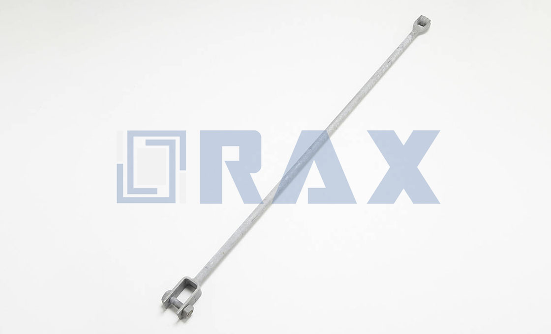
Where Are Anchor Clamps Used?
Anchor clamps secure overhead lines at dead-ends or transitions, distributing mechanical tension to support structures while preventing conductor slip.
Power Transmission and Distribution Lines
In power transmission and distribution systems, anchor clamps are critical for securing conductors at termination points where high mechanical tension is concentrated. These include dead-end towers, substations, and the transition from overhead lines to underground cables. The primary function of an anchor clamp in this context is to withstand the full breaking strength of the conductor and transfer that load safely to the supporting pole, tower, or structure without slippage.
Anchor clamps must accommodate various conductor types, such as ACSR (Aluminum Conductor Steel Reinforced), AAC (All Aluminum Conductor), and AAAC (All Aluminum Alloy Conductor). Installation requires precise alignment to ensure even stress distribution across the contact surface, minimizing the risk of micro-damage that could lead to premature failure under cyclic wind or ice loading conditions.
Telecom Fiber Optic Networks (ADSS/OPGW)
For telecommunications infrastructure utilizing All-Dielectric Self-Supporting (ADSS) and Optical Ground Wire (OPGW) cables, anchor clamps serve a dual role: providing mechanical anchorage and protecting delicate optical fibers from excessive stress or bending. Unlike metallic conductors, fiber optic cables rely on non-conductive materials and require specialized jaw designs to prevent crushing or micro-bending losses that degrade signal integrity.
Properly selected ADSS anchor clamps incorporate preformed armor rods that conform to the cable’s curvature, distributing tension evenly along the cable sheath. These clamps must also account for thermal expansion differences between the fiber core and outer jacket to avoid long-term creep or slackening. Misapplication—such as using a metal conductor clamp on an ADSS cable—can cause gradual OTDR loss increases, intermittent service drops, or catastrophic fiber breakage months after installation due to unresolved shear stress.

Comparing Hot-Forged and Cast Materials
Forging aligns internal metal grain structure for maximum strength, whereas casting creates random porosity. For critical infrastructure, forging ensures predictable performance under load.
The Metallurgical Difference: Grain Flow vs. Porosity
To understand why one method outperforms the other, imagine comparing a piece of wood to a particle board. Wood has a natural grain that gives it tremendous strength along its length. Particle board is made of wood chips and glue pressed together—it looks solid from the outside, but it lacks internal continuity. This analogy perfectly illustrates the difference between hot-forging and casting.
Casting involves pouring molten metal into a mold. As the metal cools and solidifies, the internal structure forms randomly, often creating microscopic air pockets known as porosity. While a cast clamp might look perfect on the surface, these internal voids act as weak points. In contrast, hot-forging involves heating a metal billet and applying immense pressure to shape it. This process does not just mold the metal; it refines it. The extreme pressure squeezes out internal voids and aligns the metal’s grain structure to follow the contours of the part. For hardware that must withstand constant pulling forces, this continuous grain flow is essential for integrity.
Performance Under Static and Dynamic Loads
The performance gap between these two materials becomes most evident when you move beyond simple static loads to dynamic, real-world conditions. A static load is a constant, unchanging weight—if you hang a heavy weight from a clamp and leave it alone in a lab, both cast and forged clamps might initially hold the weight. However, overhead power lines are rarely static environments. They are subjected to wind-induced vibration, thermal expansion and contraction, and ice loading.
Under these dynamic conditions, the hidden porosity in cast metal becomes a liability. The stress concentrates around those microscopic air pockets, initiating cracks that can propagate rapidly. Forged components, due to their dense and uniform structure, distribute stress more evenly across the part. This structural homogeneity prevents the localized stress concentrations that lead to sudden failure. For a B2B buyer focused on lifecycle costs, the choice is clear: the initial savings on cast hardware are quickly erased by the higher risk of failure and increased maintenance frequency.
Fatigue Resistance and Impact Toughness
Fatigue resistance is the ability of a material to withstand repeated loading and unloading cycles over time. In an overhead line, conductor vibration creates millions of tiny stress cycles over the hardware’s lifespan. Cast materials, being more brittle due to their internal inconsistencies, are highly susceptible to fatigue cracking. Once a crack starts in a cast part, it often travels unimpeded through the weak, porous structure, leading to catastrophic separation without warning.
Impact toughness refers to a material’s ability to absorb energy during a sudden high-force event, such as a falling tree branch, a heavy ice load dropping off the line, or seismic activity. Hot-forged steel exhibits significantly higher impact toughness. Because the grain structure is aligned and compressed, the material is more ductile—it can deform slightly to absorb the shock without snapping. Cast parts tend to be more brittle; when hit with a sudden impact, they are likely to shatter rather than bend. In critical infrastructure where a single failure can cause widespread outages, the energy-absorbing characteristics of forged hardware provide a necessary margin of safety that cast alternatives simply cannot match.
Do not rely solely on visual inspection to differentiate between cast and forged hardware. Surface finishes can be misleading. Always request material certification or mill test reports (MTR) that specify the manufacturing process and mechanical properties to ensure you are receiving the specified forged grade.
| Manufacturing Process | Hot-Forging vs. Casting | Aligns grain structure for superior strength |
| Tensile Strength | 20-30% Higher (Forged) | Reduces risk of catastrophic failure under load |
| Microstructural Integrity | Dense Grain Flow vs. Random Porosity | Eliminates internal voids and weak points |
| Fatigue Resistance | Superior Cyclic Load Handling (Forged) | Ensures longer service life in dynamic vibration environments |
| Impact Toughness | Higher Energy Absorption (Forged) | Optimizes performance during seismic or storm events |
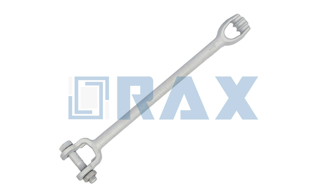
Why Zinc Coating Thickness Matters
Zinc coating thickness is not just a cosmetic spec; it is the primary mathematical determinant of an asset’s service life in corrosive environments.
Understanding ISO 1461 Specifications
In the power transmission industry, ISO 1461 is the international benchmark that dictates the quality of hot-dip galvanized coatings. This standard ensures that the zinc layer applied to steel hardware—such as anchor clamps and cross arms—is metallurgically bonded and sufficient for long-term protection. Unlike simple painting or electroplating, hot-dip galvanizing creates a robust alloy layer that is integral to the steel substrate.
ISO 1461 specifies the minimum coating thickness required based on the steel’s material thickness and section type. For structural pole line hardware typically exceeding 6mm in thickness, the standard mandates a substantial coating mass. When procuring hardware, compliance with ISO 1461 is non-negotiable. It guarantees that the zinc layer is uniform, free from bare spots, and possesses the adhesive strength necessary to withstand the mechanical stresses of installation and operation without flaking.
The Direct Link Between Thickness and Longevity
The relationship between zinc thickness and service life is linear and unforgiving. In outdoor environments, steel is constantly attacked by oxygen, moisture, and industrial pollutants. Zinc acts as a “sacrificial anode,” meaning it corrodes preferentially to protect the underlying steel. The thicker the zinc armor, the longer it takes for the environment to consume this barrier and reach the base metal.
For high-reliability utility hardware, industry best practices often target a mean coating thickness exceeding 85 microns. This level of protection is designed to withstand decades of exposure. In contrast, inferior surface treatments like electro-galvanizing often measure less than 15 microns. While these parts may look shiny initially, they lack the reservoir of zinc needed for long-term defense. In aggressive environments—such as coastal areas with salt spray or industrial zones with chemical pollutants—a thin coating can fail in as little as 3 to 5 years, leading to rust and catastrophic structural weakness.
- Zinc coating provides sacrificial protection by corroding preferentially to steel, preserving integrity even when surface scratches occur. However, the primary mechanism for long-term durability in utility hardware is barrier longevity—the physical thickness of the zinc layer that shields the underlying steel from environmental exposure over decades.
Never confuse “electro-galvanized” with “hot-dip galvanized.” Electro-galvanizing provides a cosmetic shine but offers negligible corrosion resistance for structural overhead lines. Always verify hot-dip galvanizing compliance (ISO 1461) to ensure safety.
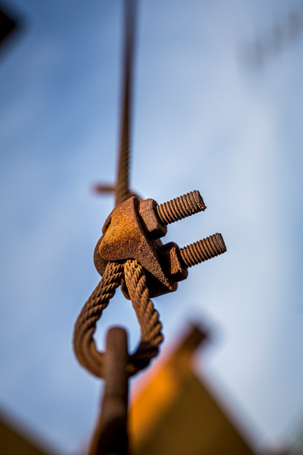
How to Install Anchor Clamps Correctly
Proper installation of anchor tension clamps is the single most critical factor in ensuring a reliable overhead line connection. Failure at this stage—whether due to surface contamination, incorrect torque, or uneven stress distribution—can lead to slippage, strand damage, or complete mechanical failure under extreme weather conditions. The following three sub-sections provide precise guidance aligned with industry standards and Rax Power’s manufacturing specifications.
Preparing the Conductor Surface
Before installing any anchor clamp, the conductor must be meticulously prepared. Any dirt, oil, oxide layer, or foreign material on the surface will compromise grip strength and accelerate fretting wear during thermal cycling. For ACSR, AAAC, or ADSS cables, use a fine-grade abrasive cloth or dedicated wire brush to clean the contact area within ±50mm of where the clamp will sit. Avoid aggressive grinding that could alter strand diameter or introduce micro-cracks.
After cleaning, inspect for strand distortion or birdcaging—a sign of prior mishandling during stringing. If found, trim and re-splice using approved methods. In our field experience across Russian and Southeast Asian projects, we’ve seen cases where contaminated surfaces reduced grip retention by up to 30% within six months. Always verify cleanliness visually and by touch before proceeding.
Applying Proper Torque Control Techniques
Torque specification is non-negotiable for bolt-type anchor clamps. Under-tightening leads to gradual loosening from vibration; over-tightening can crush strands or deform clamp geometry. Use a calibrated torque wrench set to the manufacturer’s recommended value—typically derived from bolt grade (e.g., ASTM A490), diameter (M16, M20), and lubrication condition. For example, an M20 Class 10.9 bolt without lubrication requires approximately 270 Nm; with anti-seize, reduce by ~15%.
🔧 Recommended Sequence
Step 1: Initial bolt seating requires hand-tightening in a star pattern to ensure even component alignment before torque application.
- Step 2: Final torque must be applied incrementally—typically at 50%, then 80%, then 100% of target value—while maintaining symmetrical progression across all fasteners.
- Post-torquing bolt marking with paint enables visual detection of loosening during routine inspections, supporting long-term reliability monitoring. This verification step should be integrated into the broader quality assurance protocol to serve as a final control checkpoint. By establishing a clear visual baseline, teams can ensure that the integrity of the precise torque sequences is preserved, providing a reliable reference point to distinguish between operational stress and assembly deficiencies during future maintenance audits.
Our QC team observes that installers often skip the “star pattern” step, leading to localized deformation. This may not cause immediate failure but creates stress risers that propagate under cyclic loading. At Rax Power, we mandate this procedure in our training modules for OEM partners handling our forged clamps.
Methods for Even Stress Distribution
Even stress distribution ensures no single strand bears disproportionate load, which would initiate early fatigue. When installing preformed armor rods or spiral dampers adjacent to the clamp, ensure they wrap symmetrically around the conductor with consistent pitch and tension. Misalignment concentrates force on one side, increasing risk of strand breakage under wind-induced oscillation.
For multi-strand conductors like ACSR, check alignment visually before tightening—the clamp’s inner surface should lie flush against all strands without gaps. If you’re working with ADSS fiber optic cables, pay special attention to avoiding sharp bends near the clamp entrance; even minor kinks can induce micro-bending losses exceeding 0.5 dB/km, degrading signal integrity permanently. Our engineered designs include curved entry profiles specifically to mitigate this issue.
Expert Insight: We’ve analyzed hundreds of field failures—and nearly half trace back to improper torque application or skipped surface prep. These are avoidable errors. Treat every anchor clamp installation as a high-stakes event, not just another hardware mount.
Conclusion
Anchor tension clamps secure critical load transfer points on overhead lines, preventing slip and micro-bending that compromise conductor integrity. Proper grip strength versus rated tensile strength ensures mechanical reliability under dynamic stress conditions. Hot-forged construction delivers superior fatigue resistance compared to cast alternatives, especially in high-vibration environments where impact durability directly affects long-term safety.
Our engineering team supports technical design decisions with zero obligation during early-stage planning. We provide validation on torque control methods, galvanizing thickness compliance per ISO 1461 standards, and stress distribution techniques for ADSS/OPGW installations. For specific application challenges involving anchor clamp load calculations or hardware integration, our specialists offer objective guidance backed by two decades of manufacturing experience and third-party verified quality protocols.
Frequently Asked Questions
Do anchor clamps damage ADSS cables?
Improper clamps can crush the fiber core, but specialized designs distribute stress to prevent micro-bending. It is crucial to use hardware specifically rated for ADSS cables to maintain signal integrity. The clamp must accommodate the cable’s unique mechanical properties.
How do clamps handle temperature changes?
Quality clamps are designed to accommodate conductor expansion and contraction during thermal cycling. Materials and grip mechanisms must maintain integrity across temperature swings to prevent loosening. This ensures reliable performance in varying climate conditions.
Are anchor clamps suitable for coastal areas?
Yes, provided they feature adequate corrosion protection like hot-dip galvanizing to withstand salt spray. This coating prevents rust and extends the service life in harsh marine environments. Regular maintenance is still recommended for longevity.