
Picture the back-alley pole where a full crossarm will never fit: wires leave to one side only, and the whole cantilevered arm hangs on its hardware. Correct alley arm brace installation keeps that side-mounted arm from rotating, sagging, or walking out of line under conductor load. Fitted correctly the brace is a quiet part for a decade; fitted badly it becomes the fitting the crew keeps revisiting.
From the manufacturer’s side of this hardware, two things matter: fit discipline and finish quality. RaxPower has manufactured hot-dip galvanized pole line hardware since 2003, and the 170+ people behind the range work under ISO 9001 quality management with galvanizing to ISO 1461. This guide walks the mounting sequence the way a foreman would explain it: where the brace sits, which fastener goes in first, and what to check before climbing down.
Where the Brace Sits on a Side-Mounted Arm
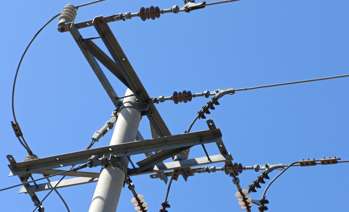
A side-mounted arm changes the load path. On a normal tangent structure the wood crossarm sits centered on the pole and its flat braces work as a pair. An alley arm bolts to one face of the pole and cantilevers out, carrying conductors where a full arm cannot go. That is why alleys and tight right-of-way spans use it.
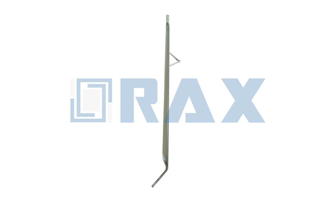
The brace is the counterpart to that cantilever. It runs from the side of the arm down to the pole below, holding the geometry at a 45-degree angle. Most designs add a welded lineman step, so the same brace doubles as a work position on the pole.
Why not just bolt on a thicker arm? Because the cantilever multiplies every pound of conductor load into a twisting moment at the pole face, and wood alone cannot fight that leverage. The brace converts the twist into a straight compression line the pole handles well.
MacLean’s alley arm catalog is a common reference for these braces, and it states the design in one line. The brace is hot-dip galvanized steel, bolted to the side of the arm and lagged to the pole at 45 degrees.
“Mount to alley arm using machine bolt and attach to pole using (2) 1/2-inch lag screws through 9/16-inch holes.” — MacLean Network Solutions, alley arm brace specification
| Reference model | Length | Mounting hole | Angle section |
|---|---|---|---|
| J1522 | 5 ft | 9/16 in | 1-3/4 × 1-3/4 × 3/16 in |
| J1525 | 7 ft | 11/16 in | 1-3/4 × 1-3/4 × 3/16 in |
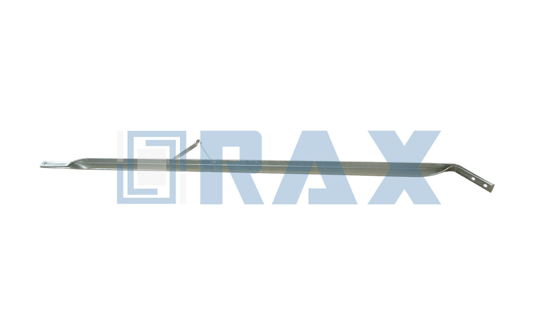
The hole size is the detail to confirm before anything leaves the truck. A 5-foot brace takes 9/16-inch holes and a 7-foot brace takes 11/16-inch holes, so truck hardware must match the print.
Before You Climb: Prep and Hardware Checklist
When the schedule puts a side arm replacement in an alley, do the thinking on the ground. Alley arm brace installation is decided before anyone leaves grade: lay the hardware out flat and count it. One brace, one machine bolt with nut and washers, and two 1/2-inch lag screws long enough for full thread engagement in the pole.
The tool list is short enough to ride a climbing belt.
- Wrench or socket matched to the machine bolt nut, plus a spud wrench for persuading holes into line.
- Drill with a lead-hole bit sized per the utility standard for 1/2-inch lag screws.
- Hammer for seating washers and a level for reading the arm.
- Tape measure to confirm brace length and hole spacing against the print.
Check the arm itself before any hardware goes on. A cracked or weather-checked arm fails no matter how well the brace fits. The same logic runs across the electrical cross arm range, since bracing only works when the member it supports is sound.
Bolt the Brace to the Arm First
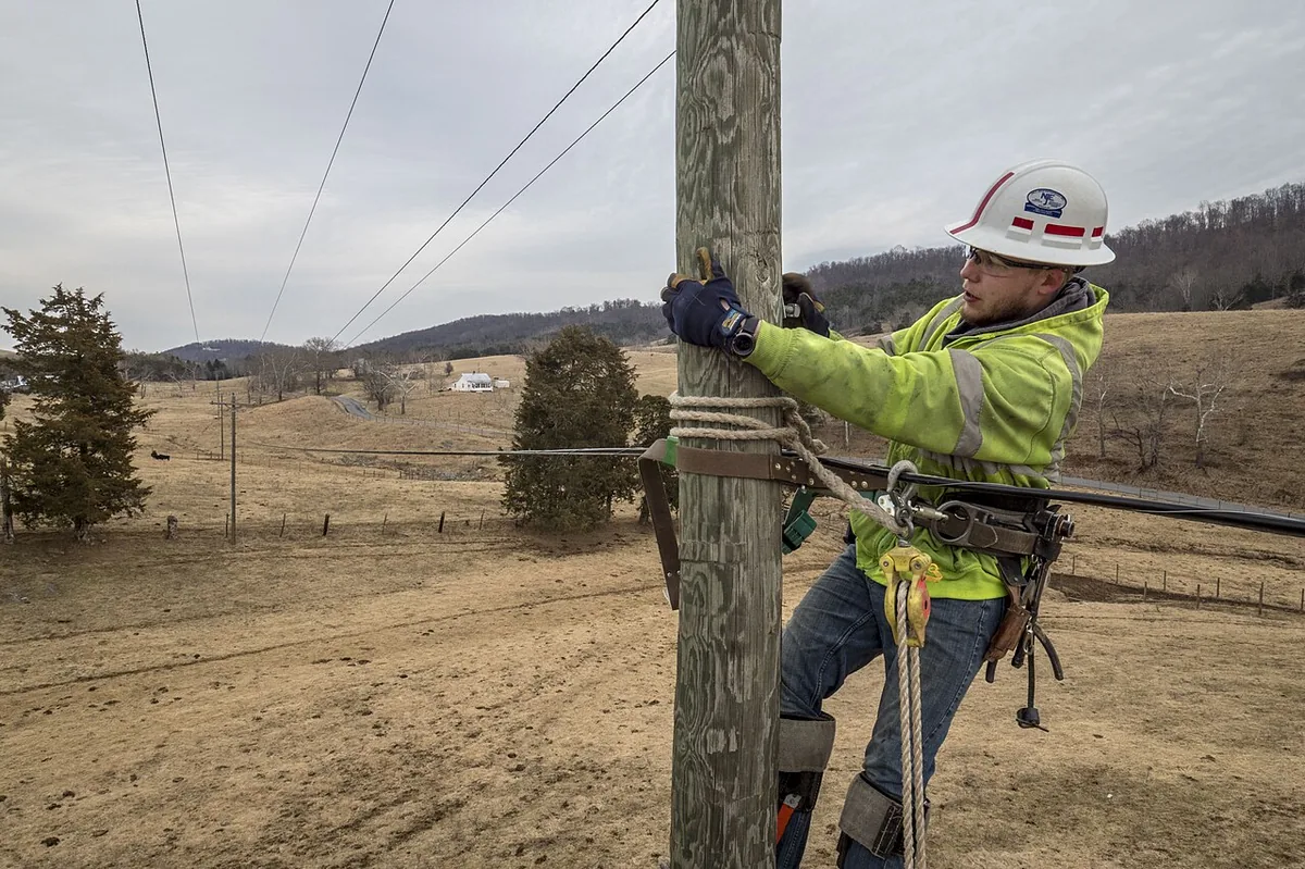
Sequence matters more than strength here. Bolt the brace to the arm while both parts are still in your hands, where the machine bolt can be started square and the brace left loose enough to swing.
The arm-side connection is a single machine bolt through the side of the arm and the matching hole in the brace. A washer under the head and the nut spreads the clamp load so the bolt does not crush wood fibers as it takes tension.
Hole alignment decides how cleanly this goes together. Start the bolt through the brace hole first, tap the shank with a hammer until it marks the arm, then drill or drift the arm hole directly off the mark. A bolt started crooked wallows its hole over time and the connection works loose in service.
Some specifications put a larger 5/8-inch bolt at this position, so read the brace drawing rather than assuming one size. What stays constant is the order: arm first, pole second, because the brace must hang free to find its angle.
Set the Angle and Lag the Brace to the Pole
With the brace swinging on its arm bolt, the pole connection becomes a geometry task. Swing the brace until it reads 45 degrees to the pole, then mark both lag screw positions through the steel.
Powertelcom’s engineering guide calls 45 degrees the most preferred angle of alignment between the alley arm and the pole, and the physics agree. At 45 degrees the brace resists both the downward sag of the cantilevered arm and the pull along the line.
Drill lead holes for the two 1/2-inch lag screws where the wood calls for them. Lead holes are commonly drilled in harder species, and practice varies by wood and utility standard.
Lag length is the quiet variable. The screw must pass through the brace and the steel-to-wood gap, then bury enough thread in the pole that the shear plane sits in the wood, not at the interface. Hold a candidate lag against the assembled brace and check that purchase before committing.
- Hold the brace at 45 degrees and mark both lag holes through the steel.
- Drill lead holes where the standard requires them, square to the pole face.
- Start both 1/2-inch lag screws by hand so the threads catch true.
- Drive or wrench each lag until the washer seats flat on the steel.
- Confirm the lineman step faces the climbing side before final tightening.
Two lag screws, not one, is what makes this fitting work. The pair stops the brace rotating around a single fastener, and the published specifications are explicit that the pole side gets two.
Snug Versus Tight: Fastening Practice That Holds
Treat the connection the way you treat a car wheel: snug in stages and re-check later. Bring the machine bolt and both lags to snug first, confirm the 45-degree geometry has not drifted, then take each fastener to final tightness.
How tight is final? Tight to the manufacturer’s specification. No published torque figure exists for alley arm brace installation, and inventing one invites crushed wood at the arm or stripped lag threads in the pole.
In our experience, the crews with the fewest callback failures are the ones who stop at snug, look at the geometry, and only then wrench.
Alignment Checks Before You Leave the Ground
Before the ladder moves, run four checks at the pole. They take two minutes, and together they turn alley arm brace installation into a routine rather than a judgment call.
- Level: the arm reads level across its length with the brace tensioned.
- Angle: the brace still reads 45 degrees after final tightening.
- Engagement: both lag washers sit flat on the steel with threads fully engaged.
- Line: conductors leave the arm spools without sideways pull on the structure.
One check belongs on the ground. Walk back until the whole structure is in view and sight the arm against the pole line. A side arm that looks true at the pole can read a few degrees off from fifty feet.
Common Fitting Mistakes on Side-Arm Construction
Most failures trace back to a handful of repeat errors. Each one is avoidable with the checklist above.
- Substituting a flat crossarm brace. Flat braces are a different family: 7/16-inch holes for 3/8-inch crossarm bolts, no lineman step, and the wrong geometry for a cantilevered side arm.
- Driving lags without lead holes in dense wood. The split starts below the surface and shows up as a backed-out screw a season later.
- Reversing the sequence. Lag the pole first and the brace can no longer swing to 45 degrees at the arm; the crew then forces the geometry and fights the hardware.
- Overtightening the arm bolt. Crushed fibers mean lost clamp load over time, which is why the manufacturer’s specification governs rather than arm strength.
- Ignoring step orientation. A welded lineman step that faces away from the climbing side gives nothing back at the next visit.
- Reusing a bent brace from the truck bed. The factory-set angle is the part; once bent, the brace will not repeat its 45-degree geometry.
Every one of these mistakes shows up in the finished geometry. The arm sags, the brace hums in the wind, or the step faces the wrong way, and a ground-level check would have caught all three.
Post-Install Inspection Rhythm for Alley Arm Braces
When the crew has left the alley, the inspection rhythm takes over. A check right after energization, then again during routine pole patrols, keeps the fitting honest for its service life.
- Lag screws have not backed out and washers remain flat on the steel.
- The arm bolt keeps tension and the wood shows no new crushing.
- Galvanizing stays intact at the bolt holes with no creep of white rust.
- The 45-degree angle has survived wind and conductor movement.
Frequency depends on environment more than on the hardware itself. Coastal air, de-icing salt, or industrial fallout argue for shorter patrol cycles, while dry inland lines can run the standard schedule. What matters is that the same eyes see the same fitting each time, because drift is gradual and easy to miss between long gaps.
Any lag that backs out twice has stripped threads in the pole. The fix is a filled and redrilled position or a relocated lag, not another turn of the wrench. Braces that arrive bent from storage should be replaced rather than straightened, because the factory-set angle is what makes the geometry repeatable.
Frequently Asked Questions
What angle should an alley arm brace sit at?
Mount the brace at 45 degrees between the side-mounted arm and the pole. Manufacturers such as MacLean list 45 degrees as the standard mounting angle, and it is the first value utilities check during inspection.
What holds the brace to the pole?
Two 1/2-inch lag screws, installed through the 9/16-inch holes in the brace. Seven-foot models use an 11/16-inch hole, so match the hardware to the hole size on the brace you are hanging.
Which bolt fastens the brace to the arm?
A machine bolt through the side of the arm, paired with the matching hole in the brace. A washer at the head and nut spreads the load instead of digging into the wood.
Do lag screws need lead holes in the pole?
It depends on the pole wood. Lead holes are commonly drilled in harder species, and practice varies by wood and utility standard. Follow the governing construction standard before driving lags.
How tight should alley arm brace hardware be?
Snug the connection, confirm the 45-degree geometry, then tighten to the manufacturer’s specification. No universal torque figure is published for alley arm brace installation, so the specification and the utility standard govern.
Alley Arm Brace Fitting: Key Facts at a Glance
- Mounting angle: 45 degrees between the brace and the side-mounted arm’s pole.
- Arm connection: one machine bolt through the side of the arm, washer-protected.
- Pole connection: two 1/2-inch lag screws through 9/16-inch holes; 7-foot braces use 11/16-inch holes.
- Typical section: 1-3/4 × 1-3/4 × 3/16 inch hot-dip galvanized steel angle.
- Reference lengths: 5 ft and 7 ft (MacLean J1522 / J1525 sizes).
- Torque: no published universal figure; tighten to the manufacturer’s specification.
Confidence at the Pole Comes From Sequence
An alley arm brace rewards the same discipline as any pole top work. Know where the part sits, follow the arm-first order, respect the 45-degree angle, and verify the geometry before leaving. RaxPower has built hot-dip galvanized pole line hardware since 2003, and the fittings that last are the ones installed to specification rather than to habit.