
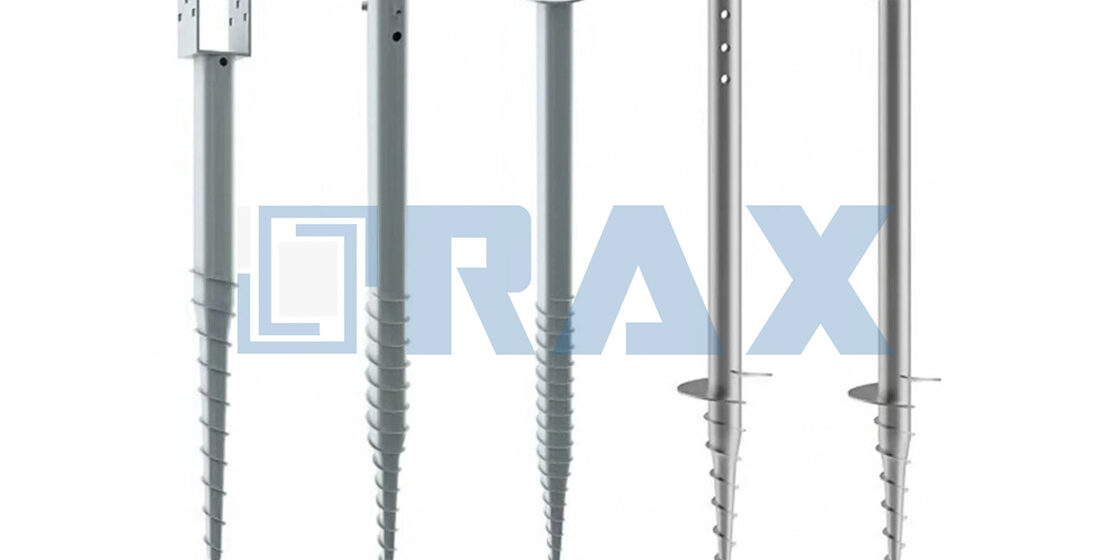
Specifying the wrong utility screw anchor sizing turns a standard foundation installation into a catastrophic failure point under high wind loads. It is not just about matching a bolt diameter; it is about understanding how that anchor transfers force into specific soil conditions. Generic concrete anchor data fails when applied to dynamic earth loads in a renewable energy application.
The expansion anchor industry sets a minimum standard of ten anchor diameters for spacing between units, yet field crews often crowd anchors to reduce excavation time. This mistake causes interaction of forces that drastically reduces holding power. We explain how to calculate load capacity by soil class and select the correct rod diameter to maintain structural integrity.
Getting the math right upfront prevents the ultimate nightmare: structural failure five years down the line due to pull-out or soil creep. This guide details the exact torque correlation required to verify your installation against safety factor standards.
How Soil Type Affects Anchor Sizing
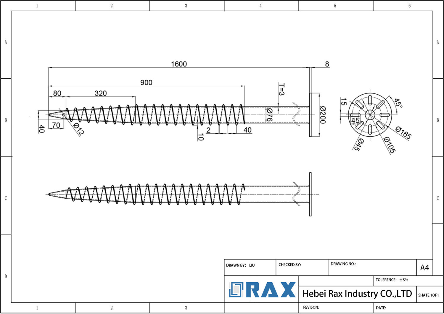
Matching helical pitch to specific ground density and soil classification is the primary determinant of anchor performance. Cohesive clays demand different engagement metrics than loose granular sands, a variance clearly illustrated by bearing capacity data: Soil Class 8 (Rock/Dense Sand) supports up to 18,000 lbs, whereas Class 5 (Loose Sand) drops to 12,000 lbs. This significant difference in load-bearing potential directly dictates the required shaft diameter and geometry for each installation.
The physical capacity of a guy anchor is rarely dictated by the steel’s tensile strength alone; it is overwhelmingly dependent on the soil’s ability to resist displacement. When planning for utility pole installations, engineers must recognize that “one size does not fit all.” A standard shaft diameter designed for firm clay will fail catastrophically if installed in uncompacted fill or loose gravel. Therefore, understanding the interplay between soil bearing capacity and shaft geometry is the absolute first step in ensuring long-term grid stability.
Soil Bearing Capacity Impact on Shaft Diameter
Shaft diameter selection is a direct function of the soil’s Ultimate Bearing Capacity (UBC). In dense, cohesive soils—such as hard clay or consolidated silt—the soil matrix provides immense frictional resistance against relatively slender shafts. Here, a smaller diameter anchor can often achieve the required pull-out rating because the soil grips the metal tightly.
Conversely, loose granular soils like dry sand or gravel offer significantly less inherent cohesion. To compensate for this low friction factor, a larger diameter shaft—or a multi-helix configuration with an increased total surface area—is mandatory. The anchor must displace a greater volume of soil to generate enough passive pressure to hold the guy wire under extreme tension. Using a shaft that is too small for granular soil results in “punch-through,” where the anchor simply bores itself deeper into the ground under load rather than holding its position.
- High-Bearing Capacity Soils (Clay/Silt): Favor standard diameter shafts (e.g., 1-1/4″ or 1-1/2″) to maximize installation speed and reduce soil displacement costs.
- Low-Bearing Capacity Soils (Sand/Gravel): Require wider diameters or extended helix lengths to increase the active gripping surface area.
- Variable Stratigraphy: If the ground profile shifts from soft topsoil to deep rock, the anchor must be sized based on the weakest soil layer surrounding the helix plates.
Helical Pitch Selection for Cohesive Versus Granular Soils
The pitch—the distance between successive flights of the screw shaft—acts as the anchor’s “gear ratio” when penetrating the earth. This geometric choice determines how aggressively the anchor bites into the ground versus how smoothly it advances. Selecting the wrong pitch relative to the soil type is one of the most common causes of installation failure.
In cohesive soils (clays), a finer pitch (tighter spacing between helices) is generally preferred. These soils stick together, creating high drag. A fine-pitch anchor acts like a slow-moving drill bit, slicing through the clay and providing immediate vertical stability without generating excessive torque resistance. The tighter coils engage more material per revolution, allowing the anchor to hold its depth securely as soon as it passes the intended grade.
In granular soils (sands and gravels), a coarse pitch (wider spacing) is vastly superior. Loose particles do not provide immediate grip; they need room to pack. A fine-pitch anchor in sand will essentially just float on the surface, grinding in place without advancing. A wide-pitch design displaces the loose soil efficiently, allowing the helix to reach the denser strata below where the actual holding power resides. Furthermore, in rocky or debris-filled sandy soil, a wider pitch prevents the voids between the flights from becoming clogged with large stones.
- Fine Pitch (Cohesive Clay): Maximizes surface contact and immediate hold in sticky soils; reduces the risk of the anchor spinning without sinking.
- Coarse Pitch (Granular Sand): Enhances penetration speed and prevents soil clogging in voids; allows the anchor to bypass loose surface layers.
- Aggressive Cutting Edges: Essential for both, but particularly for dense clays where the anchor needs to shear the soil structure to seat properly.
Thread Engagement Depth Requirements by Ground Density
The final variable is the depth at which the anchor plate fully embeds into the stable soil matrix. In soil mechanics, the “active zone” is the depth range where the soil provides meaningful resistance. Embedding the helix too shallowly exposes it to frost heave and surface erosion, while embedding it too deeply increases installation costs and risks hitting bedrock.
For soft, low-density soils, the required thread engagement depth is significantly greater. Because the soil offers poor friction, the anchor must be driven much deeper to find the necessary density to support the guy wire tension. Our engineering team often advises doubling the standard embedment depth when working with soft peat or loose fill. We test our 1/4″ thick helix anchors to ensure they maintain their structural rigidity even when driven to these extreme depths without buckling.
In dense, high-density soils, the anchor achieves full bearing capacity much closer to the surface. While a shallower installation saves time, you must ensure the shaft is long enough to transfer the load to that dense layer. In extremely dense gravels, the anchor may not sink to its full depth naturally; in these cases, pre-drilling may be required to protect the shaft threads from stripping during installation.
Pro-Tip: Always calculate your anchor length based on the depth to the first stable soil layer, not just the nominal pole height. In our rigorous IEC 120 gauge testing, we consistently find that soil variability is the single biggest factor in real-world pull-out performance.
Once the anchor is securely set in stable soil, the next critical step is determining how much force it can withstand. This requires converting dynamic environmental loads into static mechanical stress to verify safety margins.
Calculating Load Capacity for Safety
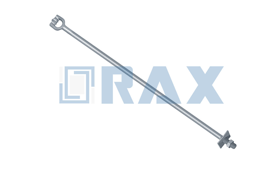
Load capacity is calculated by converting dynamic environmental forces into static mechanical stress on the anchor clamp, ensuring a minimum safety factor of 2.5x against Maximum Allowable Tension (MAT).
Converting Dynamic Wind Loads to Static Pull-Out Resistance
In utility infrastructure engineering, the primary failure mode for ADSS (All-Dielectric Self-Supporting) fiber optic lines is rarely the cable itself breaking; it is the anchor clamp slipping or shearing the cable dielectric under dynamic loads. The calculation process begins by translating variable environmental factors—such as high wind pressure and ice accumulation—into static mechanical forces. When a cable spans hundreds of meters, a stiff breeze creates a “galloping” effect that exerts lateral and torsional stress on the line hardware, which can multiply the effective tension far beyond the cable’s resting state.
To prevent slippage, engineers must convert these dynamic wind loads into the specific “pull-out resistance” required from the anchor clamp. If the anchor is undersized for this dynamic reality, the preformed wire grips will gradually grind down the outer jacket of the ADSS cable, leading to catastrophic signal loss or complete structural failure during the next storm cycle.
- Dynamic Load Aggregation: Combine the baseline tension of the cable with the added weight of ice and the lateral force coefficient of maximum expected wind speeds in your specific region.
- Static Anchor Threshold: Select an anchor clamp where the static holding force is significantly higher than the aggregated dynamic load to account for sudden shock loads.
- Jacket Integrity Check: Ensure the anchor’s internal grip geometry distributes pressure evenly to prevent point-loading that cuts into the PE (Polyethylene) jacket.
Safety Factor Application for Extreme Weather Conditions
Because ADSS cables are highly sensitive to electric fields and mechanical stress, applying a strict Safety Factor (SF) is non-negotiable. For standard overhead line applications, we mandate a minimum SF of 2.5. This means the breaking strength of the anchor clamp must be at least two-and-a-half times greater than the Maximum Allowable Tension (MAT) of the installed cable.
In extreme weather conditions—such as the heavy ice loads common in Russia or typhoon-prone Southeast Asian coastlines—this factor should be increased to 3.0x. Our engineering teams often specify custom hot-forged alloys for these climates because traditional casting methods can result in microscopic pores that fail under such extreme, amplified safety margins.
- Baseline Safety Factor (2.5x): Standard protection for dry, temperate climates with minimal wind shear.
- Extreme Weather Safety Factor (3.0x+): Required for regions with high wind velocity, severe icing, or complex terrain that induces turbulence.
- Sag-Tension Trade-off: Higher safety factors mean stiffer installations; proper sag-tension calculations must be performed simultaneously to ensure the pole or tower isn’t overloaded.
Verifying Breaking Load Against IEC Gauge Testing Standards
Reliance on theoretical calculations is a common pitfall for inexperienced buyers. The only objective way to verify that an anchor clamp meets the IEC 61238-1 (formerly IEC 120) standards is through rigorous, third-party gauge testing. While many generic manufacturers provide vague “high-strength” claims, Rax Power subjects every batch of hardware to precise load cells that mimic real-world stress angles to validate both the mechanical grip and the ultimate tensile strength.
During our internal double-review processes, we test samples to ensure they reach their specified breaking load without suffering permanent deformation at the mounting bolts. If a clamp fails before reaching its rated limit during testing, it indicates a metallurgical flaw in the forging process, directly violating the ISO 1461 compliance required for long-term utility durability.
- IEC 120 / 61238-1 Compliance: Mandates standardized testing procedures to ensure consistent pull-out strength across all manufactured batches.
- Pull-Out Strength Validation: The anchor must resist forces attempting to slide the ADSS cable longitudinally without damaging the external fibers.
- In-House Load Cell Verification: We utilize calibrated hydraulic gauges to measure exact kilonewton (kN) resistance prior to shipping.
Choosing Rod Diameter and Length
Anchor rod dimensions must be scaled to soil resistance while ensuring sufficient burial depth for lateral load management. Helix thickness is strictly 1/4″ to ensure rigidity under high torque loads without bending, as referenced in the Golden Data, to prevent premature failure from over-torquing.
Structural Integrity and Diameter Scaling
The fundamental challenge in utility anchoring is bridging the gap between theoretical load requirements and the physical reality of ground penetration. Engineers often default to the smallest diameter that meets the minimum pull-out calculation to save on material costs. However, using a minimal rod diameter—such as a standard 3/4 inch or 1 inch for heavy-duty applications—creates severe mechanical stress during installation. The steel must endure high torsion without snapping, which means the rod diameter dictates not just the holding strength, but the installability of the entire system.
In dense clay or compacted loam soils, forcing a narrow-diameter rod deeper into the ground increases friction exponentially. This friction translates directly into torque. If the rod diameter is too small for the given soil density, the contractor risks shearing the shaft entirely before the anchor reaches its design depth. Conversely, utilizing a heavier gauge 1-1/4 inch to 1-1/2 inch rod distributes the driving force more effectively, allowing the helix to cut through hard pan and rocky strata with significantly less risk of structural fatigue.
- Light-Duty Environments (Loam/Sandy): Standard 3/4 inch rods are typically sufficient here, provided the helix pitch is optimized for loose aggregate.
- Medium-Duty Environments (Compacted Clay): Moving to a 1 inch rod provides the necessary cross-sectional area to handle higher torsional loads without yielding.
- Heavy-Duty Environments (Rocky/Hard Pan): Larger diameters (1-1/4 inch to 1-1/2 inch) paired with thick-walled geometry are mandatory to prevent bending under extreme downforce.
If your project specification calls for a very long anchor length (e.g., over 10 feet), always upgrade to a larger rod diameter. The longer the unsupported span inside the borehole during drilling, the higher the chance of the shaft bowing or buckling. A thicker rod acts as a stiffer drive shaft.
Length Optimization and Depth-to-Diameter Ratios
Determining the correct anchor rod length goes beyond simply adding up the soil layers. The critical metric is the depth-to-diameter ratio and the resulting torque required to reach that depth. A common mistake procurement managers make is ordering fixed-length anchors based solely on pull-out tables, without accounting for the difficulty of the specific drilling conditions at the job site.
When dealing with deep installations, the leverage exerted on the rod becomes a primary failure point. Extending a rod length from a standard 6 feet to 10 or 12 feet drastically multiplies the bending moments experienced by the hardware during the screwing process. To compensate for this increased length, the helix geometry and the driving collar must be reinforced. In scenarios requiring maximum embedment, extending the rod length past 12 feet usually necessitates custom manufacturing to ensure the torque transfer remains effective all the way to the bottom helix.
Avoiding Installation Torque Overload
The ultimate test of an anchor rod’s dimensions is its behavior when it hits a “hard stop”—an impenetrable layer of rock or dense gravel. When the anchor cannot advance further, the driving machine continues to apply torque. If the rod diameter is undersized relative to the length being used, this excess torque will twist the steel past its yield point, causing the anchor to snap below the surface. This is one of the most costly errors in pole-line construction, leaving a broken anchor completely inaccessible underground.
To mitigate this, engineers must evaluate the total length of the rod against its cross-sectional area. Heavier rods offer a much larger safety margin when hitting unexpected subsurface obstructions. They allow contractors to apply the final driving torque required to seat the anchor firmly without risking catastrophic shear failure. Understanding this relationship prevents field delays and ensures the structural longevity of the guy wire support system.
| Rod Diameter | Standard Length | Load Rating | Soil Type | Rax Power Advantage |
|---|---|---|---|---|
| 3/4 inch (Standard) | 3 ft to 6 ft | Light to Medium Duty (~4,000 lbs) | Loam, Clay, Sandy Loam | ISO 1461 Galvanizing (>85 microns); automated 1mm dimensional tolerance. |
| 1 inch | 5 ft to 8 ft | Medium Duty (~6,000 – 10,000 lbs) | Dense Clay, Compacted Soil | Hot-forged structural integrity; SGS certified double-review QC process. |
| 1-1/4 inch to 1-1/2 inch | 6 ft to 10+ ft | Heavy Utility/Transmission (10,000+ lbs) | Rocky, Hard Pan, Extreme Environments | Heavy-duty applications in extreme environments require specialized geometry and robust material specifications. Features 1/4 inch thick helix anchors for high-torque rigidity and Hot-dip galvanizing per ASTM A153 Class C for corrosion protection in wet or rocky soils. |

Torque and Power Needs for Installation
Key Takeaway: Installation torque is the definitive field metric for verifying holding capacity. Contractors must match hydraulic output to soil resistance to achieve target depth without exceeding the anchor’s yield strength or damaging the foundation soil.
The Relationship Between Torque and Holding Capacity
In the installation of earth anchors and pole line hardware, torque is not merely a measure of tightness; it is the direct indicator of soil interaction and ultimate holding power. As a screw anchor penetrates the ground, the installation torque measures the resistance of the soil against the helix plates. Industry practice dictates a correlation between the final installation torque and the ultimate holding capacity, often expressed as a specific multiplier depending on soil classification. This relationship allows field crews to verify capacity in real-time without waiting for laboratory pull-out tests.
However, relying solely on torque requires adherence to strict mechanical limits. If the torque exceeds the torsional yield strength of the anchor shaft—often a risk in dense, rocky soils—the shaft can twist or shear before reaching the designated depth. This creates a “false positive” high torque reading where the anchor is actually failing structurally rather than engaging the soil. Therefore, installation protocols must define a maximum torque threshold that is distinct from the target capacity torque.
Machinery and Hydraulic Power Requirements
Drive head selection and power source capability are critical for maintaining installation integrity under high shear strength conditions. The power unit must provide sufficient continuous torque to overcome soil shear strength while allowing for precise control. For high-capacity utility anchors requiring torques exceeding 4,000 ft-lbs, high-flow hydraulic drive motors with planetary gear reduction systems are the standard to prevent sudden shock loads.
| Anchor Application | Typical Torque Range | Required Power Unit |
|---|---|---|
| Light Duty (Small Guys, Solar Racking) | 100 – 500 ft-lbs | Hand-held torque wrenches or portable hydraulic units |
| Medium Duty (Distribution Poles) | 500 – 2,500 ft-lbs | Skid-steer mounted auger drives or dedicated hydraulic heads |
| Heavy Duty (Transmission Towers) | 2,500 – 6,000+ ft-lbs | High-torque excavator mounted drives (10-30 GPM flow) |
Spacing and Installation Thresholds
Spatial arrangement of anchors directly influences soil mass stability and individual holding capacity. The industry standard mandates a minimum spacing of ten (10) anchor diameters between adjacent units to prevent overlapping stress zones. Additionally, anchors must be placed at least five (5) diameters from any unsupported edge to avoid soil shear failure.
For machine screw anchors and expansion anchors used in concrete or rock bases, the holding power is entirely dependent on the friction between the expansion shell and the base material. If the drilled hole is oversized or irregular—common in field conditions with worn bits—the expansion mechanism cannot engage properly, leading to slippage under load. Always verify hole diameter against the anchor’s specifications; tolerances are typically measured in thousandths of an inch. Using an anchor designed for irregular holes is essential when exact drilling precision cannot be guaranteed.
Protecting Hardware Integrity During Installation
While achieving installation torque is vital, protecting the galvanized coating and physical geometry of the hardware is equally important for long-term service life. Excessive lateral pressure or sudden impact during the driving process can flake off the zinc coating, exposing the base steel to corrosion. For pole line hardware such as guy clamps and secondary racks, the applied torque must be sufficient to prevent cable slippage but calibrated to avoid crushing the conductor’s outer strands or the jacket of ADSS cables.
- Torque Wrench Calibration: Ensure mechanical or hydraulic torque wrenches are calibrated regularly to prevent over-tightening, which is a primary cause of U-bolt failure.
- Alignment: Misaligned drive heads introduce bending moments that can snap square shaft anchors during high-torque installation.
- Depth Monitoring: Torque must be monitored continuously as a function of depth. A sudden drop in torque usually indicates a soil void or a sheared shaft, both of which require immediate investigation.
Conclusion
Getting anchor sizing right means looking past just the shaft diameter. The soil type determines your true holding capacity, so you must adjust helical pitch for cohesive versus granular ground. If you ignore the safety factor for extreme wind loads, the project fails. Torque readings during installation remain the only real-time truth meter you have.
Stop guessing on load calculations. Our engineering team can verify breaking loads against IEC standards and ASTM A153 galvanizing specs for your specific site conditions. Send us your soil reports and wind load data. We will run the numbers to confirm the holding strength matches the pole’s requirements before you ever start digging.
Frequently Asked Questions
What is the difference between helical and expanding anchors?
Helical anchors derive holding power from friction along their shaft and the bearing capacity of their helical plates. Expanding anchors rely on mechanical interlock against surrounding soil or rock through radial expansion. Selection depends on soil composition, with helical types often preferred for uniform clay or sand profiles.
Which standard governs guy wire anchor sizing?
ANSI/IEEE 1048 and IEC 61238 provide guidelines for the design and testing of hardware used in guy wire systems. These standards define safety factors and load requirements based on conductor weight and environmental loads. Proper sizing ensures the anchor can withstand maximum tension without exceeding allowable soil bearing pressures.
How to prevent anchor corrosion in wet soil?
Hot-dip galvanizing according to ISO 1461 provides a robust zinc coating that protects steel from electrochemical corrosion. This method ensures a mean coating thickness exceeding 85 microns, offering long-term durability in aggressive environments. Additional protective coatings may be specified for highly acidic or saline soil conditions.
When should double-arming bolts be used?
Double-arming bolts are essential for securing multiple conductors or providing redundant support in high-tension applications. They distribute mechanical stress evenly across the pole line hardware assembly. Using these bolts enhances system reliability and prevents single-point failures in critical suspension or termination points.
Does Raxpower offer custom anchor designs?
Raxpower provides OEM and ODM services to create specialized anchor solutions tailored to unique project requirements. Custom mold development allows for precise adjustments to helix geometry and shaft dimensions. This flexibility ensures optimal performance in non-standard soil conditions or specific utility tender requirements.