
High on many distribution poles, a galvanized spindle carries a pin insulator and the tied conductor above the structure. The pole top pin application question is narrower than it first sounds. Which line positions reward that hardware, and which need a crossarm pin, a line post insulator, or a bracket instead?
In our experience at RaxPower, the question reaches the order desk in two voices. A caller rebuilding an aging crossarm line asks whether a spindle at the pole top can carry the phase. A builder of a new single-phase spur asks which pin thread matches the insulators already on the truck. Both callers are really asking the same thing: where does this hardware fit, and where does it not.
Where a Pole Top Pin Earns Its Place
Picture a single-phase spur leaving the feeder across open country. Bolting one pin to the top of each wood pole lifts the phase a full crossarm-height above the structure, with no crossarm steel to buy, bolt, or inspect. That pole-top construction is the classic application, and utility construction manuals give it dedicated standard sheets.
Cowlitz County PUD in Washington State, for example, keeps one standard sheet for the single-pin top and another for a double-pin arrangement. Double-pin tops set two phases on one structure without a crossarm, which keeps a rebuild light where road crossings or awkward spans make full crossarm work slow.
Rural utilities standardized this construction early. Electrification-era materials lists accepted the pin-and-insulator pair as the default single-phase support, and major catalogs still carry RUS-approved models of this pin for those programs. Long standardization is why a staking sheet can name the part and every bidder's catalog opens to the same hardware. Buying against those sheets also keeps quotes comparable, because every bidder prices the same geometry.
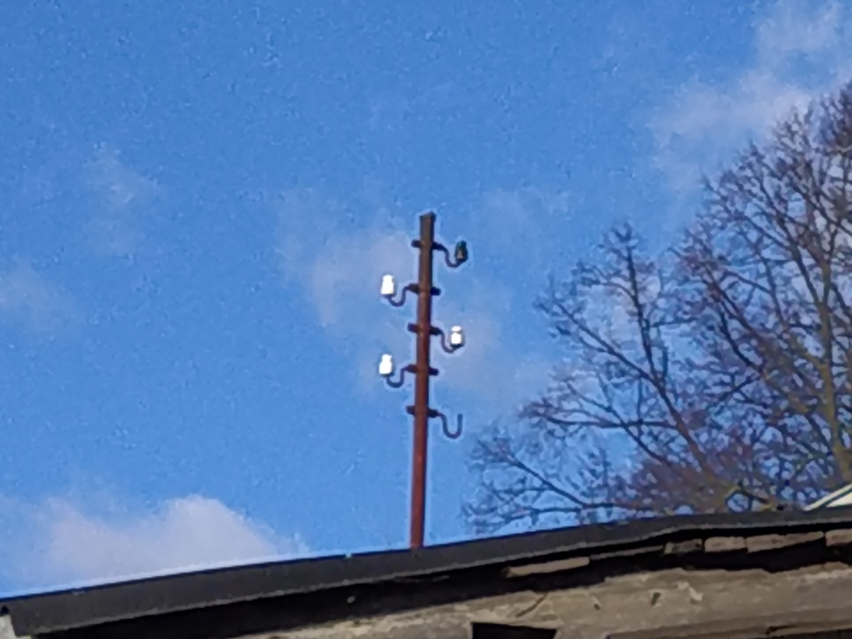
The same construction suits a top-phase addition on a three-phase run: one phase rides the pin while the other two stay on the crossarm below. Crews gain working clearance between the top phase and the pole-mounted equipment underneath it.
What the Pin Must Carry Before It Qualifies
A pole top pin application lives or dies on load-path honesty. The pin carries the insulator, the tied conductor, and the transverse wind push of both spans, all on a cantilever. Ductile iron pins in this product class list a minimum ultimate strength of 2,000 pounds (8.9 kilonewtons), a number worth checking against conductor tension and span wind before ordering.
- Conductor weight and full tension at the tie point
- Transverse wind loading across both spans at the pole
- The insulator's spindle thread, matched before the truck rolls
An ultimate strength is a failure point, not a working load. Design practice keeps everyday tensions well under it, and the utility's own safety factor decides the margin. That is why the catalog number matters less than the span data behind it. The same pin gives a different answer on a sheltered spur and on a long open stretch.
The mounting details earn their keep in the field. A slotted lower mounting hole lets a crew align the bolt without wrestling the pin, and the flange mounts either against the pole or away from it. The thread area ships with a vinyl coating, which removes the cast lead threads that older catalogs offered and that crews no longer want to handle.
Pole Top Pin or Crossarm Pin
The second decision is vertical position on the structure. A crossarm pin bolts through a crossarm and carries its phase out where the arm reaches. The pole-top spindle bolts to the pole top and holds the phase directly over the structure, higher and tighter to the wood.
Choose the pole top position when clearance matters more than spacing: the phase rides above transformers, arresters, communication cable, or a tired crossarm. The crossarm wins when phase separation matters more, because several pins on one arm hold conductor spacing constant, as in our cross-arm insulator guide.
The pin itself works like a truck hitch: small hardware that everything behind it leans on. By the time the trailer is swaying, the hitch has already told you everything about the load. Under-rate it and the trailer decides the outcome, which is why the strength check above comes before any catalog number.

When a Post Insulator Takes Over
When the load grows past what a threaded spindle wants to hold, the application moves to line post insulators. A post bolts directly to the pole or crossarm through a stud and carries a much larger cantilever load without a separate pin underneath. The assembly shortens too: one insulator, one stud, one bolt pattern, instead of pin plus insulator plus tie wire.
Rural electrification catalogs formalized this swap decades ago, and the clause is still the cleanest one-line answer to a rebuild request. In the REA acceptable-materials lists, a post insulator with its mounting fitting can stand in for the pin-and-insulator pair, on small and large conductor distribution work alike.
So the post is not a rival product so much as the next duty class up, and our pole insulator guide shows how each family sits on the structure. The same logic runs in reverse on light builds: keep the pin where the load is small, and spend on posts only where the loading sheet demands them. Underbuild attachments tell the same story, because a communication or secondary cable asks almost nothing of the structure and never justifies a post by itself.

Voltage Bands and the Pin Ceiling
Voltage draws the boundary more sharply than load does. A pin insulator stands the full line-to-ground voltage across one body on one rigid spindle, so every voltage step demands a longer, wider shed stack. That geometry is why pin-type construction tops out in the low-30-kV class, and our pin insulator anatomy guide treats 33 kV as the practical working edge.
North American distribution classes sit comfortably inside that envelope, and the mid-30-kV range is where pin insulator catalogs stop. Above it, the pole top pin application hands off to line post insulators, braced posts, or suspension strings, which spread the same voltage across more leakage path. The hardware is not failing at that point; it is simply out of its class.
Thread standardization softens the boundary. Because spindle sizes are shared across the class, an uprate inside the pin range usually means new insulators rather than new steelwork. The pin below often stays on the pole. Crossing out of the class is different: the whole head layout changes, and the post or bracket budget arrives with it.

Line Angles and Corner Poles
Angle duty bends the decision one more way. At a corner, the conductor pulls the insulator in two directions at once, and the resultant leans off the pin's axis. Small angles stay on pin construction with a side tie holding the conductor in the neck groove.
Past a few degrees, dedicated hardware earns its place. The angle crossarm pin exists precisely for this case: an insulator pin assembly for distribution crossarms that provides stable support where conductors change direction. Bigger changes of direction call for posts or strain hardware, which take the full tension instead of resisting its sideways pull.
That is the honest boundary of the pole top pin application: it is a tangent-position answer. Forcing it into a corner load is the misapplication a crew discovers fastest, usually as a leaning insulator on the first hot afternoon.
Match the Pin Thread to the Insulator
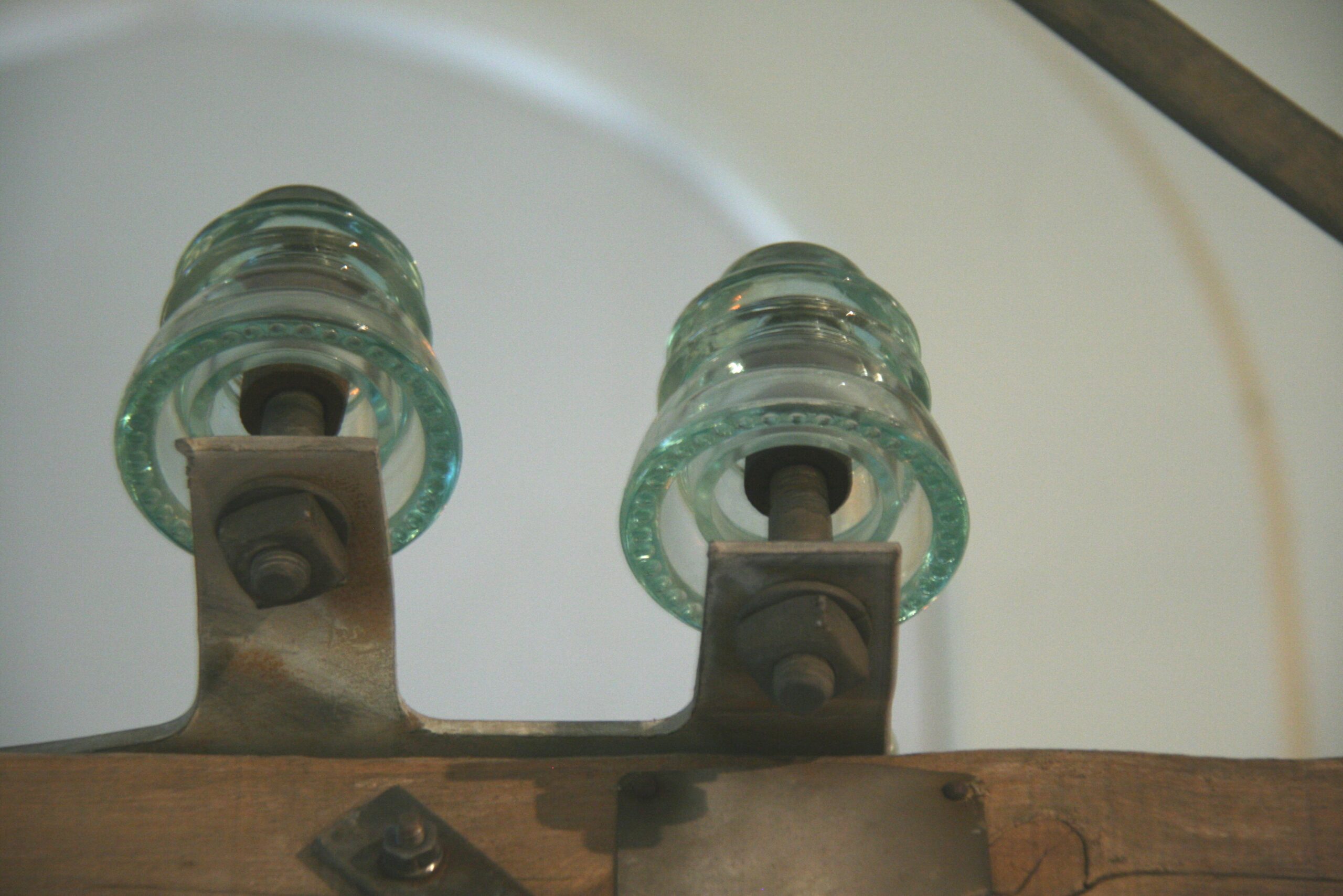
Thread fit decides whether the application survives contact with the truck bed. Two spindle sizes dominate distribution work: 1-inch and 1-3/8-inch diameters, and the insulator must be ordered with the matching spindle thread. A mismatched pair is not a field repair; it is a returned pallet.
Older catalogs cast the thread in lead. Modern production swaps in nylon alloy threads or coats the seat in vinyl. That takes lead handling out of the crew's day and keeps the insulator groove aligned on the pin. Both options thread the same two spindle sizes.
Catalog competitors handle the same details their own way. MacLean mounts pressed steel pins against the pole with 5/8-inch bolts, offering nylon alloy or cast lead threads. Thermal diffusion galvanizing to ASTM A1059 serves as the corrosion upgrade over standard hot-dip galvanizing. The same two thread sizes hold across related pin families: the angle crossarm pin pattern, for example, specifies 1-inch and 1-3/8-inch lead threads meeting CSA requirements. Ordering the insulators against the pin drawings, rather than from memory, keeps the pair matched before it reaches the warehouse.
Which Hardware Fits Which Situation
The pole top pin application summary below compresses the decision the way a staking technician would sketch it on a tailboard. Read the situation first, the default hardware second, and the reason last.
| Situation | Default hardware | Why it fits |
|---|---|---|
| Single-phase tangent on wood poles | Pole top pin + pin insulator | Clearance above the structure, no crossarm steel to buy |
| Top phase on a rebuilt three-phase line | Pole top pin | Adds a phase without touching the crossarm below |
| Tight phase spacing along a run | Crossarm pins on a crossarm | The arm holds conductor separation constant |
| Heavy conductor or long spans | Line post insulator + stud | Higher cantilever rating in a one-piece assembly |
| Corner or angle change | Angle pin, post, or strain hardware | The resultant of two tensions needs an aligned axis |
| Aging crossarm replacement, sound poles | Pole top pin conversion | One bolted spindle replaces the tired steelwork |
No table replaces the loading sheet. Wind span, conductor size, and grade of construction all move the boundary, and the local standard drawings settle the final call. When two rows seem to fit the same pole, the heavier-duty choice wins, because nobody ever replaced a post for being too strong. Treat the rows as a first sort, not the last word.
The Fit Decision in Brief
Specify the spindle-on-top construction where the phase can ride above the structure on a tangent, inside the distribution voltage classes, at loads the rating can honestly carry.
The short version: single-phase spurs and top-phase additions are its natural habitat. Crossarms hold phase spacing, posts take the heavy cantilever, and corners need angle or strain hardware. Threads come in 1-inch and 1-3/8-inch. Match those five boundaries to the staking sheet and the pin will be the cheapest correct hardware on the pole.
At RaxPower we quote the pin and the post side by side for exactly this reason. The order desk walks the fit decision daily, and quotes that respect it are the ones that ship once and stay up. Right position, right voltage class, right rating: that is the whole application answer.
Frequently Asked Questions
Is a pole top pin the same as a crossarm pin?
No. A pole top pin bolts to the pole top and carries one phase directly over the structure. A crossarm pin bolts through a crossarm, where several pins on one arm hold phase spacing constant along the line.
What voltage class suits pin-type construction?
Pin-type construction is a distribution-class solution through the low-30-kV range, because each voltage step forces a longer, wider insulator body onto one rigid spindle. Past that edge, line post insulators take over.
Which insulator thread sizes match the pin?
Two spindle sizes dominate: 1-inch and 1-3/8-inch diameters. Current production coats the thread area in vinyl, and the flange can face against or away from the pole.
Can a post insulator replace a pole top pin?
Yes on distribution rebuilds. The REA acceptable-materials lists allow a post insulator and its fitting to substitute for the pin assembly and its insulator on small and large conductor work alike.
What strength rating should the pin meet?
Ductile iron designs list a minimum ultimate strength of 2,000 pounds (8.9 kilonewtons). Check that rating against conductor tension and transverse wind load before ordering the pin and its insulator.