
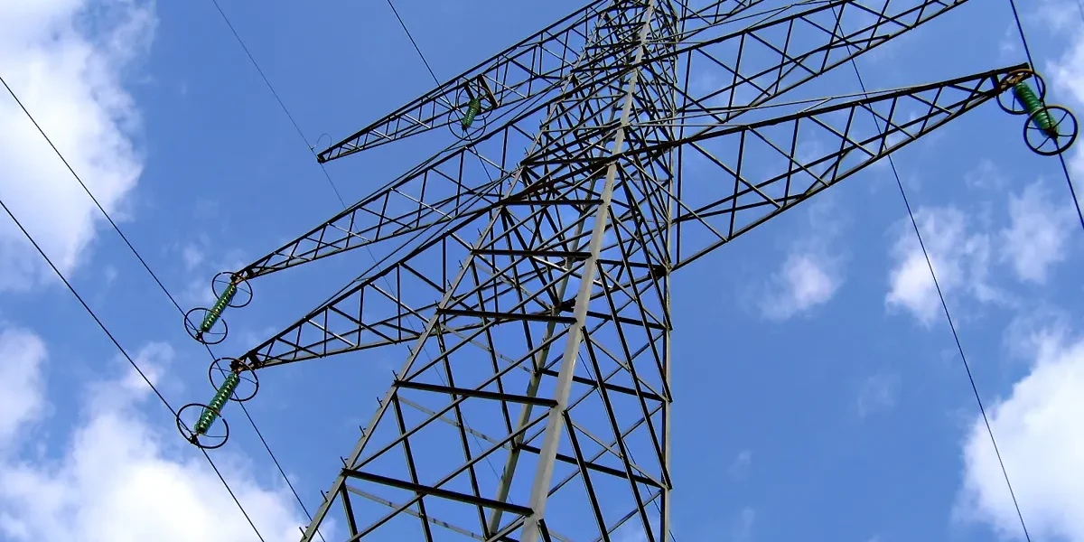
On the buyer's side of a line project, the crossarm brace exists first as a drawing callout: a flat bar, two punched holes, a coating note, a weight. That single line decides whether a framed arm stays square through its service life or starts leaning after the first heavy storm. Buy it as a commodity fitting and the mistake resurfaces in the field. Hole centers miss the arm print, or the coating has already failed at the punch.
A crossarm brace transmission project treats the fitting as a framing member, not a catalog commodity. Five inputs fix the specification: arm length and span, duty class, attachment hardware, coating class, and quantity with pairing. Each input maps to a datasheet line or a named construction standard, which is what makes the order verifiable before it ships.
Start From the Brace Drawing First
Every crossarm brace transmission buyer should read the datasheet before the quote, because the drawing settles arguments that catalog prose cannot. A flat brace drawing carries six fields: bar section, overall length, two hole diameters, hole center distance, and finish. RaxPower publishes its cross arm brace datasheet with all six, and the numbers are worth quoting in full.
Stocked flat braces come in 20, 26, 28, and 32 inch lengths, all punched from 1-1/4 by 1/4 inch steel bar. The arm end takes a 7/16 inch hole and the pole end a 9/16 inch hole, each center positioned one inch from a rounded tip. Hole center distances run 18, 24, 26, and 30 inches across the four lengths, and unit weights range from 1.68 to 2.69 pounds.

Two more fields sit below the dimensions. Ultimate tensile strength is listed at 410 to 560 N/mm², and the finish line names the galvanizing standard rather than just the word galvanized. Those two lines carry the duty and corrosion decisions covered later in this guide, so confirm them against the structure drawing rather than the catalog page alone.
What a Crossarm Brace Does On Structures
A framed crossarm wants to tip toward the span once conductors take tension. Two braces run from the underside of the arm down to the structure face, one from each side, forming a V. Together they convert the tipping moment into compression in one member and tension in the other, forces the pole handles easily.
That load path explains most of the specification. The brace works as a strut, so bar section and steel grade set the strength margin, while hole positions set whether the pair can be framed without re-drilling on site. It also explains why braces ship and install as pairs; a single member leaves the arm free to rotate under unbalanced load.
The brace is a framing element, not a conductor fitting, and it inherits every geometry decision the arm makes. For how the arm itself carries phase spacing, conductor load, and mounting equipment, see the electric cross arm breakdown. The rest of this guide stays on the brace side of that joint.
Flat Iron, Pipe, and V-Type Brace Options
Three brace families cover nearly every framing order, and they are not interchangeable. Flat iron braces are the bar-stock pair described above, the default for tangent arms on wood and composite structures. They are punched, not welded, so the one-piece bar keeps its full section and the rounded ends seat flat against the pole face.
Pipe braces replace the pair with a single member on long arms. Seattle City Light construction standard 0100.09 is explicit about the switch. Its material schedule calls one steel pipe brace for standard 11-foot wing arms, sized at 1-1/4 inch pipe, 9 feet 1 inch long. One deep-reaching pipe member does the work a short flat pair cannot reach.

V-type braces, sold as angle braces, are one-piece angled members that preset the V geometry in the steel itself. They frame faster where crews repeat the same arm design across a run of structures, and RaxPower lists them alongside the flat pair in its electrical cross arm range. The framing drawing, not habit, picks the family.
Five Selection Inputs for Crossarm Brace Transmission Specs
A crossarm brace transmission order converges quickly once five inputs are fixed in writing. Each one maps to a datasheet field or a schedule line, and each one fails in a visible way when it is guessed.
| Selection input | What to fix | Where it bites |
|---|---|---|
| Arm length and span | Brace family and length class | Fit between arm bolt line and pole face |
| Duty class | Bar section and steel grade | Strength margin under span load |
| Attachment hardware | Hole diameters and bolt schedule | Bolt and lag fit on site |
| Coating class | Named galvanizing standard | Corrosion life at holes and edges |
| Quantity and pairing | Members per arm, plus spares | Framing completeness per structure |
The table reads top to bottom in the order the decisions cascade. Arm geometry picks the brace family, duty picks the section, and hardware, coating, and quantity follow from the framing drawing. The four sections after this one take the inputs that carry the most field risk.
Matching Brace Length to Arm Span
Length is the input buyers most often misread, because the governing dimension is hole center distance, not overall bar length. The brace must swing from the arm bolt line down to the pole face at a workable angle. That reach is set by the distance between the two punched centers. On stocked braces it runs 18, 24, 26, and 30 inches against overall lengths of 20, 26, 28, and 32 inches.
Measure the arm, not the catalog. Take the depth from the arm bolt line down the structure face to the planned lag position, and compare that figure against the hole center distance column. A brace two inches short of the mark forces a steep angle, and a steep angle loads the lag screw in pull-out rather than shear.
Where an arm design sits outside the four stocked lengths, the bar can be engineered to the drawing. Hole center distance, end angles, and hole diameters are all adjustable before the punch, which is why the framing drawing should travel with the inquiry. Confirm the drawn angle still clears guys and equipment mounted below the arm line.
Duty Class: Distribution vs Transmission Loads
Duty class is where a crossarm brace transmission order diverges from a distribution order. Longer arms carry heavier conductor tension, wider spans add wind and ice load, and the brace section that suits a distribution tangent arm can be undersized for subtransmission framing. The datasheet section line, 1-1/4 by 1/4 inch on stocked braces, is the field that scales.
Utility practice shows how the framing answer changes with duty. Seattle City Light reserves flat brace pairs for standard tangent arms. Its 11-foot wing arms move to a single 9-foot pipe brace, because the wider arm needs deeper reach and a heavier member. The lesson generalizes: brace family and section follow the arm, and the arm follows the structure class.
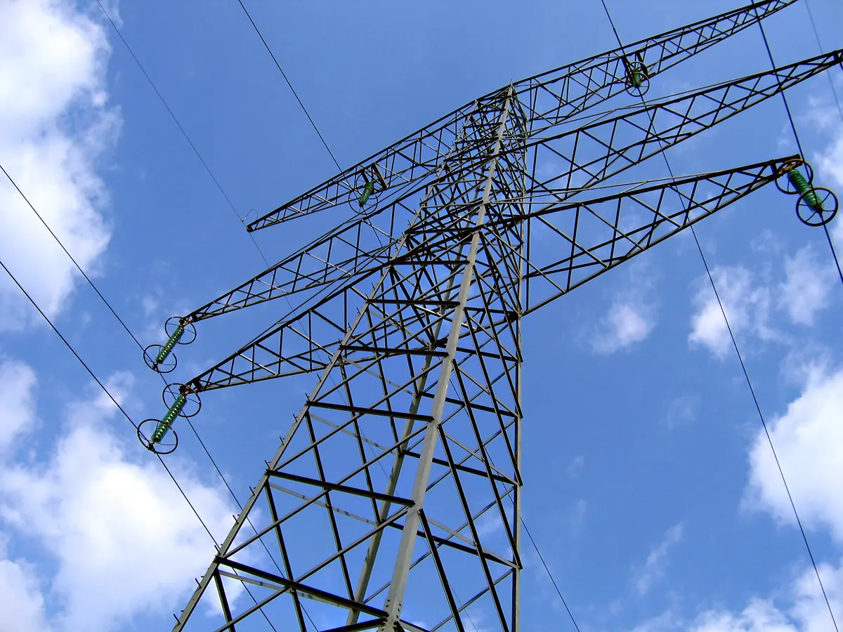
No published load table lets a buyer convert a brace bar size into a transmission duty rating, so the verification path is documentary. Take the conductor tension, span, and arm class from the structure design, and have the brace section checked against that framing calculation before the order is placed. A supplier who engineers to the drawing can state the margin; a catalog cannot.
Bolt and Lag Hardware for Braces
Hardware is selected through the holes, and the two holes are not the same size. The 7/16 inch hole at the arm end pairs with a 3/8 inch machine bolt, one size under the hole. The 9/16 inch hole at the pole end clears a lag screw with room to start true. Order braces without the matching fastener schedule and the hardware truck arrives to a fit it cannot resolve.
Named schedules remove the guesswork. Seattle City Light pairs its flat braces with 1/2 inch machine bolts at the arm and 1/2 inch lag screws at the pole. That schedule assumes braces drilled for the larger bolt. A 1/2 inch bolt cannot pass a 7/16 inch hole, so the bolt follows the brace print, not a generic chart.
The flat brace schedule adds round washers and 4 inch and 6 inch lag lengths. The wing-arm pipe brace takes a 5/8 inch bolt with round, square, and spring lock washers, plus two 1/2 inch lag screws, on its two-point connection.
Washer class matters as much as bolt size. Round flat washers spread the clamp at wood, the square washer bridges the pipe seat, and the lock washer keeps the assembly tight under vibration. Compatible fittings worth grouping on the same order include U-bolts, pigtail bolts, and double arming bolts, which RaxPower publishes in galvanized steel or aluminum.
Galvanizing Class and Coating Acceptance
Coating class is a named standard, not an adjective. Hot-dip galvanizing to ISO 1461 or ASTM A123 is the specification to write on the purchase order. RaxPower braces carry a mean coating thickness above 85 microns under those standards. The punched holes and rounded ends are where coatings thin out, so the standard matters most exactly where the steel was worked.
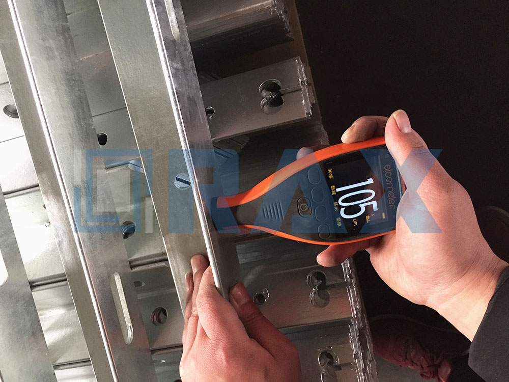
Acceptance is verifiable in two documents. The first is the galvanizing certificate that should travel with the shipment, naming the standard and batch. The second is a coating thickness gauge reading at the punch edges on sampled braces, the same measurement shown in quality-control photos on the product page. Mechanical verification runs alongside: the 410 to 560 N/mm² tensile band and testing to IEC 120, with third-party certification such as SGS on file.
Sourcing Braces From a Manufacturer
Quoting a crossarm brace transmission package starts from the structure framing drawing, not from a catalog SKU list. A manufacturer that controls its own hot forging can adjust length, hole configuration, angle, and material to the drawing. That is the difference between sourcing a part and sourcing a verified fit. Ask which stages happen in-house; forging, punching, and galvanizing under one roof shorten the feedback loop when a drawing changes.
Certification is the second sourcing filter. ISO 9001 covers the quality system, and galvanizing certificates under ISO 1461 or ASTM A123 should be requested per batch at order time. Samples are worth the wait on a first order. Hang the sample brace on the mating arm before the full run ships, because a hole that misses by a fraction repeats across every carton.
Documentation closes the loop. A datasheet with the six drawing fields, a coating certificate, and a mechanical test record make the order auditable years later. That is precisely what utility purchasers and EPC contractors need at handover.
What to Check Before Ordering
The checklist below compresses the five inputs into purchase-order lines. Confirm each against the datasheet or the framing drawing, and get the confirmation in writing rather than in a call.
| Spec line | Confirm against | Failure if missed |
|---|---|---|
| Bar section, 1-1/4 x 1/4 in stocked | Datasheet and duty calculation | Undersized member on heavy framing |
| Holes, 9/16 in pole and 7/16 in arm | Arm print and fastener schedule | Bolt or lag mismatch in the field |
| Hole center distance, 18 to 30 in stocked | Measured arm depth to lag position | Steep brace angle, lag in pull-out |
| Galvanizing to ISO 1461 or ASTM A123 | PO coating note and certificate | Thin coating at punched edges |
| Pair count per arm plus spares | Framing drawing | Short shipment stalls the framing crew |
- Fix the brace family against the framing drawing: flat pair, single pipe brace, or V-type.
- Match hole center distance to the measured arm depth, not to a neighboring order.
- Confirm hole diameters against the bolt and lag schedule before the hardware order closes.
- Write the galvanizing standard and the mean coating figure into the purchase order.
- Require the coating certificate and mechanical test record to travel with the shipment.
- Count members per arm and add spares before releasing the quantity.
How Selection Errors Surface on Delivery
Most brace problems announce themselves at the truck, which makes receiving the cheapest inspection point on the project. Check carton counts against the pair-per-arm figure first, then sample braces against the datasheet: bar section, hole diameters, center distance, and tip rounding. A mismatch caught at the gate is a credit note; the same mismatch at the structure is a standby crew.
Coating damage is the second delivery find. Braces scuffed to bare steel in transit can be rejected or re-galvanized per the standard. Thin coating at the punch edges points to a process issue upstream instead. Record either finding against the batch certificate so the correction lands with the right shipment.
Field symptoms trace back to the same inputs. An arm that drifts off level between inspections usually carries a brace angle or hardware fit chosen by habit. A lag that loosens in its first season often started in an oversize hole. Correcting the input costs a purchase order line; correcting it on the pole costs a climbing crew. Crews fitting the correction can follow the cross arm brace installation sequence.
Crossarm Brace Questions Buyers Ask
How long is a standard crossarm brace?
RaxPower stocks flat braces in 20, 26, 28, and 32 inch lengths with hole center distances of 18, 24, 26, and 30 inches. For crossarm brace transmission orders beyond stocked sizes, lengths and hole configurations are engineered to the arm drawing.
Why are crossarm braces installed in pairs?
Two braces form a V under the arm, one taking compression and the other tension as span load tips the arm. A single flat brace leaves the arm free to rotate under unbalanced load.
What size bolt holds a crossarm brace?
Arm bolts follow the print: a 7/16 inch hole pairs with a 3/8 inch bolt. Seattle City Light 0100.09 calls a 5/8 inch bolt with washers for the 11 foot wing-arm pipe brace.
What galvanizing standard should the brace meet?
Specify hot-dip galvanizing to ISO 1461 or ASTM A123. RaxPower braces carry a mean coating above 85 microns, and the coating certificate should travel with the shipment rather than live in the catalog.
Does every crossarm need two braces?
No. Standard tangent arms take a flat brace pair, while long wing arms can use one steel pipe brace instead. Follow the framing drawing for brace type, count, and schedule. Crews can follow the cross arm brace installation sequence.
Crossarm Brace Selection: Key Facts at a Glance
- Stocked flat braces: 1-1/4 x 1/4 inch steel in 20, 26, 28, and 32 inch lengths, hole center distances 18 to 30 inches, unit weights 1.68 to 2.69 lb.
- Holes: 9/16 inch at the pole end for the lag screw, 7/16 inch at the arm end for the machine bolt, centers 1 inch from rounded tips.
- Strength and finish: ultimate tensile strength 410 to 560 N/mm², hot-dip galvanized to ISO 1461 or ASTM A123 with mean coating above 85 microns.
- Brace families: flat iron pairs on tangent arms, one steel pipe brace on 11-foot wing arms per Seattle City Light standard 0100.09, and one-piece V-type braces.
- Hardware schedules: 1/2 inch bolts and lags on flat braces; 5/8 inch bolt with round, square, and lock washers plus two 1/2 inch lags on the pipe brace.
- Verification: coating certificate with the shipment, mechanical testing to IEC 120, and third-party certification such as SGS.